Sjfw
Release status: working
| Description | Firmware for Atmega644p and greater processors.
|
| License | GNU GPL v3
|
| Author | |
| Contributors | |
| Based-on | [[]]
|
| Categories | Firmware
|
| CAD Models | |
| External Link |
See sjfw on Github for the latest version of this firmware.
Extensively tested on RAMPS and Gen4.
Contents
SUPPORTED HARDWARE
- Prusa Reprap RAMPS1.2 (experimental!)
- Prusa Reprap RAMPS1.3
- Thing-O-Matic Gen4
FEATURES
- Control pad and full HOSTLESS printing!
- Temperature history graph
- Advanced Gcode Pipeline
- ISR driven movement
- Acceleration
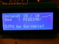
- LCD Temperature Display
- "Volumteric" Printing
- SD Card support
- Tested and working with Pronterface Reprap host, the best Reprap host there is presently.
COMPILING AND INSTALLING
This firmware is NOT Arduino-IDE based.
You need to be able to use GNU Make, and have lib avr, avr-gcc, and avrdude installed. Optionally, having perl allows you to use the provided reset script and host software.
Examine and edit the top of the Makefile to your satisfaction. Optionally, look under rampsXX/config.h or gen4/config.h to change the firmware settings.
make clean && make && make upload
IMPORTANT NOTES ON USING THIS FIRMWARE
- The Gen4 Support is perfectly useable on a Reprap, but it is designed for use by the Thing O Matic. The important part is this; the Gen4 support ASSUMES you are using the Makerbot Thing-O-Matic EC Firmware on your EC. If you are not, you must install that on your EC first! If you are not using a ToM on Gen4 you will also need to edit the steps settings and speeds/accel in the config file to suit.
- The latest release has been tested to work with the EXCELLENT "Pronterface" Host by Kliment: https://github.com/kliment/Printrun
CURRENTLY KNOWN BUGS/ISSUES
- Config file for ramps13 includes everything; the others may need some love for control panel and lcd support.
- Motors that are set to disable after a move only get disabled a few moves thereafter. This should work fine, but don't forget a M84 at the end of your gcode to turn off all motors.
- SD card support works in the firmware, but is not compatible with the Gcodes that Pronterface emits. This firmware presently has two Gcodes for SD access:
M204 - fetch filename from SD M205 - print last fetched filename
- THE SD CODE MAY FAIL ON LONG FILENAMES. 8.3 FILENAMES WORK FINE IN THE MEANTIME.
- THERE IS NO HOMING GCODE. There probably never will be; it's unnecessary. Just make a move towards the endstops that is longer than the platform, then mark that spot with a G92 and carry on. Here's some examples:
Here's my start.gcode from my Prusa:
M104 S190 (start heating up, but don't wait)
G92 X0 Y0 Z0 E0 (set current position)
G1 X-300 Y-300 F2000 (Move to X/Y endstops)
G92 X0 Y0 Z0 E0 (set current position)
G1 X5 Y5 (Move away from X/Y endstops)
G92 X0 Y0 Z0 E0 (set current position)
G1 X-10 Y-10 F800 (Move back to X/Y endstops)
G1 Z-200 F400 (Move to Z endstop)
G92 X0 Y0 Z0 E0 (set current position)
G1 Z5 F400 (Move away from Z endstop)
G92 X0 Y0 Z0 E0 (set current position)
G1 Z-10 F400 (Move to Z endstop)
G92 X0 Y0 Z-0.7 E0 (set current position - note endstop is .7 below platform height)
G1 X0 Y0 Z30 F2000 (move to waiting position)
M109 S190 (wait for extruder to reach temperature)
Here's the start.gcode from my ToM:
M104 S180 (start heating extruder, but don't wait)
M140 S50  (start heating platform, but don't wait)
G92 X0 Y0 Z0 E0 (set current position)
G1 Z200 F800 (move to Z endstop)
G1 X-200 Y-200 F2000 (move to X,Y endstops)
G92 X0 Y0 Z0 E0 (set current position)
G1 Z-5 X5 Y5 F800 (move away from XYZ endstops)
G92 X0 Y0 Z0 E0 (set current positions)
G1 Z10 X-10 Y-10 F400 (move to XYZ endstops)
G92 X-5 Y-25 Z116.7 E0 (set current positions)
G1 X0 Y0 Z50 F6000 (move to waiting position)
M84 (disable motors)
M109 S180 (wait for extruder to reach temperature)
NOTES ON CONNECTING AN LCD AND KEYPAD
There are plans to add i2c support to sjfw as soon as I have an i2c LCD and/or keypad with which to test code. In the meantime, sjfw supports hitachi-protocol text-mode LCDs using a parallel interface. These are as common as dirt; basically any 16x2 or 20x4 character display with 16 pins is going to be the right thing. I recommend 20x4, but the firmware supports both sizes. It /does not/ support single-line displays. If you'd like that support, a patch would be simple.
Keypads are supported using a row/column scanning method. This is a very common style of keypad, and also easy to make yourself. You should expect to see 8 pins for a 4x4 button pad grid. If you have a datasheet, the pins will be labeled COLUMN1-4 and ROW1-4. While it is easy to change sjfw to support 9-button pads or any random number of buttons, currently the code rather assumes you have 16.
THIS MEANS AT A MINIMUM, YOU MUST HAVE (LCD)7 + (KEYPAD)8 = (TOTAL)15 FREE DATA PINS ON YOUR MOTHERBOARD TO USE THE CONTROL PANEL SUPPORT. You can use just the LCD for temperature display without attaching a keypad, if you'd like to save pins. Or you can wait for i2c support.
I currently have only 'standardized' on wiring for RAMPS13. I welcome suggestions for the other systems.
CONNECTING THE LCD TO RAMPS13
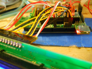
The provided configuration assumes you will connect the LCD in 4-bit mode to AUX2.
- D63 = RS
- D42 = RW
- D65 = E
- D59 = Data4
- D64 = Data5
- D44 = Data6
- D66 = Data7
The Data0 - Data3 pins on the LCD are left disconnected. The contrast pin on the LCD can be wired to ground, or run through a pot between ground and +5v for adjustable contrast.
WHY IS D48 THE UNUSED PIN ABOVE WHEN D65 WOULD MAKE MORE SENSE? Simply because D48 is burned out on my RAMPS board.
CONNECTING THE KEYPAD TO RAMPS13
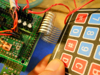
The provided configuration assumes you will connect a 16-button keypad using 8 pins of AUX-4.
- D16 = ROW1
- D17 = ROW2
- D23 = ROW3
- D25 = ROW4
- D27 = COL1
- D29 = COL2
- D31 = COL3
- D33 = COL4
CREATING NEW AND DIFFERENT CONFIG FILES FOR SJFW
If you would like to run SJFW on a configuration that is not currently provided, please contribute your patches after you are done!
SJFW does not use any Arduino-based code, and therefore does not use the Arduino pin numbers, for better or for worse. This means in the configuration files, the pins are specified using Port and pin designations, not Arduino digital pin numbers. If you need some help determining the right values, there are cheatsheets in the util/ directory of the firmware distribution comtaining maps between Arduino pins / Atmega port/pins for Atmega644p and Atmega1280/2560.
You should create a new directory for your config file, and then point the makefile at it.


