Template:RepRapPro hot end assembly/de
Contents
Werkzeuge
In diesem Bauabschnitt benötigen Sie folgende Werkzeuge
- Inbusschlüssel
- Kleiner Schraubendreher
- Zangen
- einstellbarer Gabelschlüssel
- Hitzquelle (kleine Lötlampe plus Fön/Lötkolben)
- Schraubstock
Bauteile
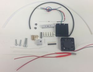
Der Huxley Heizwiderstand ist ein 6,8 Ohm, wohingegen der des Mendel ein 2,7 Ohm Typ ist.
Es gibt außerdem unterschiedliche Crimpstecker für die Verbindung der Kabel zum Widerstand und dem Temperatursensor (rotes Rechteck). Siehe unten.
Es gibt einige Arbeiten in diesem Bauabschnitt, bei denen Sie Stücke von Teflon zuschneiden müssen. Es ist unbedingt erforderlich, jegliche Reste/Staub davon zu entfernen, damit diese nicht in den Extruder gelangen können. Teflonstaub wandert in die Düse und verstopft diese wenn es in das Gerät gelangen sollte.
Schritt 1: Der heisse Teil des hot End
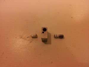
Prüfen Sie, daß der Heizwiderstand in das etwas größere Loch im Heizblock passt. Die Widerstände haben etwas unterschiedliche Durchmesser. Der Temperatursensor sollte in sein Loch passen. Die Herstellungstoleranzen sind hier geringer.
Wenn der Widerstand zu groß ist, klemmen Sie den Heizblock in den Schraubstock und vergößern das Loch vorsichtig mit einem 5mm Bohrer. Achten Sie darauf, den Bohrer gerade in das Loch zu führen. Lassen Sie den Bohrer mehrmals hoch und runter laufen lassen, vergrößert sich das Loch langsam. Wiederholen Sie dies solange bis der Widerstand passt. Die ideale Passung ist, wenn der Widerstand saugend paßt, aber nicht schwer hineingeht. Sie sollten nur sehr wenig Kraft aufwenden um den Widerstand in seinen Sitz zu bringen. Wenn er zu schwergängig ist, wird die Isolierung beschädigt. Legen Sie den Widerstand zur Seite. Sie werden ihn gleich wieder benötigen.
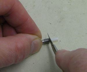
Sie werden ein kurzes Stück (ca. 15mm) 3mm Teflonröhrchen benötigen. Dieses brauchen wir später für line the heater barrel. Wenn Sie die 3mm Durchmesser Versio an Ihrem Extruderantrieb haben, schneiden Sie dieses Stück mit einer scharfen Klinge rechtwinklig von dessen freiem Ende ab. Wenn Sie die 4mm Version haben, dann liegt Ihrem Bausatz eben dieses kurze Stück 3mm Teflonröhrchen genau zu diesem Zweck bei. So oder so, legen Sie das Stück auf die Seite, wir brauchen das erst später.
Nehmen Sie das freie Ende des Extruderantrieb Teflonröhrchens. Wenn Sie die 4mm Version haben, dan formen Sie mit einem Bleistiftspitzer einen kleinen Kegel von ca. 2mm an dessen Ende. Achten Sie darauf, nicht zu weit zu schneiden, Teflon ist sehr weich.
Schrauben Sie den Messingverbinder an das freie Ende des Extruderantriebs Teflonröhrchen. Schauen Sie während dessen durch das andere Ende des Verbinders, damit Sie das Röhrchen nur bis zum Ende des Gewindes schrauben - nicht weiter. (Eine Lupe kann hier hilfreich sein).
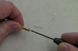
Das einschrauben des Röhrchens in den Messingverbinder, verringert dessen Innendurchmesser. Verwenden Sie einen 2mm Bohrer am besten an einem Handbohrfutter um den Innendurchmesser vorsichtig auf ca. 2mm zu vergrößern.
Schieben Sie ein Stück 1,75mm Filament vom anderen Ende her durch den Bowdenzug um diesen von Teflonstaub zu befreien (Siehe die Warnung oben bzgl. Teflonstaub). Stellen Sie sicher, daß das Filament ohne irgendwo zu haken sauber und leichtgängig durch den Bowdenzu hin und her läuft.
Umwickeln Sie das kürzere Gewinde um
Wickeln Sie Teflonband um das kürzere Gewinde der Edelstahlhülse und die Düse:
Stellen Sie sicher, daß das Band nicht die Löcher abdeckt und lassen Sie den glatten Teil der Hülse frei (oder schneiden das Band nach dem umwickeln mit einer Klinge ab). Die Hülse hat ein großes Temperaturgefälle während des Betriebs von einem Ende zum anderen (über 200°C). Aus diesem Grund ist es wichtig, daß dieser Bereich frei bleibt, damit die Hitze zirkulieren kann.
Schrauben Sie die Hülse und die Düse in den Heizblock so ein, daß diese sich in der Mitte treffen. Die Düse gehört auf die Seite des Blocks mit der kleinen 2mm Bohrung (diese nimmt später den Temperatursensor auf).
Setzen Sie den Isolationskonus auf die Düse. Die Düse sollte etwas weiter aus dem Block herausragen als der Konus tief ist. Der Konus wird später auf die Düse geschraubt und die Düse muß ein klein wenig aus dem Konus herausschauen.
Da sich Aluminium bei Erwärmung mehr ausdeht als Messing oder Edelstahl, besteht die Gefahr, daß die Düse oder die Edelstahlhülse sich während des druckens lockern. Um dies zu verhindern müssen Sie diese festziehen während der Block heiß ist. Um dies durchzuführen, spannen Sie den Block mit einer möglichst kleinen Ecke, aber so, daß er sicher nicht herausfallen kann, im Schraubstock ein.
Stellen Sie den einstellbaren Gabelschlüssel auf die Flachstellen der Düse ein und halten Sie eine Flachzange bereit.
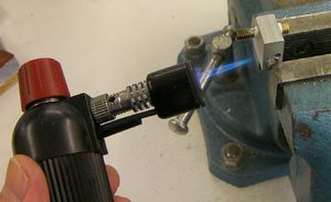
Verwenden Sie die Lötlampe, um den Block zu erhitzen:
Gehen Sie behutsam vor, damit der Aluminiumblock nicht schmilzt. Aluminium schmilzt bereits bei ca. 660°C und die Flamme einer Lötlampe kann über 1000°C erreichen. Es ist ausreichend den Block auf etwas über seine spätere Arbeitstemperatur zu erhitzen (ca. 300°C). Halten Sie die Lötlampe soweit von dem Block weg, daß nur das weniger heiße Ende der Flamme diesen erreicht. Bleiben Sie dabei nicht länger an derselben Stelle. Während der Block heiß ist, halten Sie die Hülse mit einer Zange (nicht den Block!) und ziehen die Düse mit dem verstellbaren Gabelschlüssel an. Es reicht ein kleiner Drehwinkel von ein bis zwei Grad aus um sicherzustellen, daß sich weder die Hülse noch die Düse während des druckens lösen können.
Belassen Sie danach den Block im Schraubstock bis dieser abgekühlt ist.
Stchritt 2: Das Kühlsystem
Nehmen Sie das kurze Stück Teflonröhrchen, welches Sie zuvor zur Seite gelegt hatten und stecken es in die andere Seite der Edelstahlhülse. Schneiden Sie es mit einer scharfen Klinge bündig ab.
Nehmen Sie einen 5mm Bohrer und drehen diesen vorsichtig in dem Stück Teflonröhrchen, daß Sie eben eingesetzt haben, um dieses ein ganz klein wenig zu weiten. Entfernen Sie sorgfältig jeden Teflonkrümel.
Schrauben Sie jetzt das Ende der Bowdenzughülle // No more Bock today, tomorrow is even a good new day for getting this done...
Now screw the brass bowden end piece (with the PTFE bowden tube screwed into it), into the Aluminium heatsink block (the long thin one with five holes in it). Once fully screwed in, screw the free end of the barrel into the M5 hole in the Aluminium heatsink block until it meets the brass piece. Now unscrew the brass piece by 1/4 turn, screw the barrel in to meet it, and finally tighten the brass piece with some pliers. This will result in the barrel and bowden end pieces being locked together inside the heatsink block.
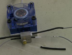
The heater block should be parallel with the heatsink block (and with the power resistor).
Peel the sticky backing off the fan and heatsink. This is quite tough - you may need to pull with pliers. Take care not to put stress on the delicate plastic fan. The easiest way once you have a corner off is to hold that with long-nosed pliers and to roll them over the back face of the heatsink like peeling the lid off a tin of sardines.
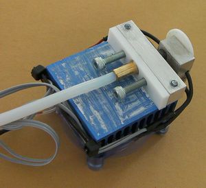
You can put a little heatsink grease on the aluminium cooling block if you like. Attach it to the fan with the two longer screws. Put the two shorter screws through the PTFE spacer and screw them a few turns into the block.
You will see that there are slots in the heatsink attached to the fan that blow down on the heater block. Put a piece of sticky tape over those slots.
Step 3: The heater resistor and temperature-measuring thermistor
If the heater resistor is too lose in its hole in the heater block, wrap it in a little PTFE tape. Either way, put some heat-sink grease on it to give good heat contact with the aluminium block. The best heat-sink grease to use is the stuff with titanium dioxide in it - this looks like an artist's tube of white oil paint (for good reason - that also contains TiO2; but don't use paint!).
DO NOT force the heater resistor into the heater block. This may result in some enamel being scraped from either or both ends of the resistor, leading to a short circuit. If the resistor is too large, gradually enlarge the hole using a 5mm drill bit.
Use two adjacent wires from the ribbon cable for each end of the heater resistor - four in all. This is to increase the current capacity.
The wires across the ribbon cable in order go like this:
- Wire with the colour stripe: Thermistor
- Thermistor
- Fan + volts
- Fan Ground
- Heater resistor Wire 1
- Heater resistor Wire 1
- Heater resistor Wire 2
- Heater resistor Wire 2
Resistor wires 1 and 2 are arbitrary - the resistor has no polarity.
This order is designed to keep the heater wires (which experience high current transients) as far as possible from the thermistor wires (which convey the very low current temperature signal to a high-impeedance input).
You can either use the ferrule crimps (right in the red box in the parts picture) or the connector crimps (left). The connector crimps just plug onto the resistor and thermistor wires, which is simple. The ferrule crimps are a bit more fiddly, and they make a permanent connection.
The advantage of the connector crimps is that you can plug and unplug the wires. The advantage of the ferrules is that they give a better quality (i.e. lower resistance) connection.
Alternative 1: Ferrule crimps
The pictures show the ferrule crimps and the single wires.
Bare about 10mm on the end of the resistor connector wires and crimp them onto the ends of the resistor's leads. Put heatshrink on and use a soldering iron or hairdryer to shrink it.
The picture shows the left-hand side complete, and the right hand side waiting for the crimp to be slid over the join followed by crimping. It also shows conventional heatshrink. To shrink the PTFE heatshrink you will have to hit it with a flame - a mere soldering iron won't touch it.
The thermistor should fit in its hole - they are manufactured to a tighter tolerance. It will be a little undersized. But the crimps on the thermistor wires won't fit through the hole, so you have to crimp one wire after the thermistor has been pushed through the block.
Put about 20mm of PTFE heatshrink over the thermistor and shrink it on with a flame (try not to scorch things). Put the thermistor in the block - the PTFE should make it a snug fit. Crimp and then heatshrink over the connections to either end. With the ribbon cable for the second thermistor connection, don't forget to slide the heatshrink onto it and away from the join before you make the join - you won't be able to get it on afterwards.
Alternative 2: crimp sockets
Simply crimp the sockets on the ends of the thermistor and heater resistor wires, then shrink black heatshrink over them to insulate them. Remember that each end of the heater resistor needs two wires - bare them and twist the ends together before fitting the crimp sockets.
This step is easiest with the correct tool, such as this one http://www.rapidonline.com/Tools-Equipment/Ratchet-Action-Crimp-Tool-Ht225d-85-0262 If you do not have such a tool, this advice is worth following http://www.youtube.com/watch?v=KEm2PuHBt4Y
Connecting up
Bend the wires up the side of the heat sink. Do not pull them tight - they need a little slack to accommodate movement and expansion. Attach them at the top of the heatsink with two cable ties chained together, one of them running through the top slot in the heatsink.
Trim the excess off the cable ties.
Use a meter to check that the resistance between the wires and the aluminium block is infinite and that nothing is shorting.
Also check the resistance of the heater resistor and the thermistor by measuring from the far ends of the wires. The Mendel heater should be just under 3 ohms or the Huxley just under 7 ohms. The thermistor should be about 100K.
Step 4: Fan wires and nozzle insulator
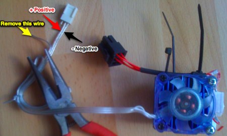
You need to cut one wire off the fan. Looking at the picture below, use a red and a black felt-tipped pen to mark the positive and negative fan wires. Trace them right back to the fan and mark them there.
Cut the socket off (leaving your marks on the fan side of the cut...), then remove the extraneous wire.
Screw the PTFE insulating cone onto the nozzle.
