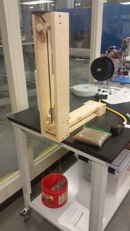
Belt Compliance Measurement
Release status: working
| Description | Belt Compliance (stretch) Test Stand
|
| License | |
| Author | |
| Contributors | |
| Based-on | [[]]
|
| Categories | |
| CAD Models | |
| External Link | []
|
Contents
Introduction
The purpose of this page is to propose a standardized, easily replicable test stand and procedure to obtain belt compliance data. Currently, real performance data for the tiny belts used in 3d printers is difficult to find and this makes engineering the system difficult. A standard test method could help the community generate data to fill this information gap and to compare belt suppliers, brands, and models quantitatively. The bill of materials, construction details, theory, and use are covered in this page.
Background
The engineering of industrial mechatronic systems requires some key pieces of data. The amount of compliance (spring-back) of the belts is one such critical piece of data. During acceleration force is applied against the belts creating position error. Position error is the difference between where the motor should have moved the load and the actual position of the load. Finding belts with the minimum compliance (stretchiness) and maximum stiffness will create a system with the best positioning accuracy and most faithful reproduction of the model being printed.
Links to other information on belts
Proposed Method
The proposed method of measuring belt compliance is to suspend a long arm from a belt and apply force by hanging weight from the arm. The movement of the arm is measured with a dial indicator. The reason for using the long arm is to keep the measuring surface located below the indicator without affecting the measurement. The tension in the belt also helps keep things centered.
Materials Required
- 1ea Dial Indicator (Currently Harbor Freight Tools No. 623)
- 1ea 96 inch (8ft) long 1x4 pine boards.
- 1ea Piece of plywood 3" x 3" to make knobs from
- 4ea 2 inch Drywall Screws for the clamp knobs (coarse thread flat head screws)
- 18ea 1-5/8" Drywall Screws (coarse thread flat head screws)
- 2ea pieces of 3/4" x 3/4" x 2.5" wood to make the clamp blocks
Construction
Print out the templates at 1:1 scale (life size) and use them to make the pieces for the test stand. Most print dialog boxes give the option to adjust the scale of the print to get the template exactly at 1:1. This makes building the test stand easier to build. If you can't get them to print out at 1:1, just used the drawings the old fashioned way :)
Most bolts have some marks to indicate the grade of the bolt and the manufacturer. The bolt head of the 1/4 inch bolt should be filed flat so the indicator has a flat surface to measure from without these marks. The upper tongue pivot should be drilled while mocked up to the frame because it can be aligned to match the rest of stand after it is already constructed.
For the clamp blocks and knobs, the idea is to make the knob thread onto the screws so that any simple object a screw can be driven into can be used for a knob. A piece of broom handle or a plug cut out of a board with a hole-saw would work fine. If the stand gets a lot of use the knobs will wear out. They can be replaced with knobs that can accept a machine screw or wing nuts and machine screws if that happens someday. I used a rectangular hunk of wood for mine and that worked fine. Maybe there is a stick in the yard?
