Calibration
You RepRap works well? Great!
Did you ever hold a caliper on your parts to see wether these 10 mm in the STL file match on the printed part? Wether this 8 mm hole actually has 8.0 mm diameter, not 6.8 or 8.3? No?
Here we talk about how to not disappoint you in case you or your friend ever does. A Mendel can be calibrated to be as accurate as the mechanics allow.
Contents
Prerequisites
Before starting calibration, your build process has to be pretty stable already. You have to know which temperatures work best, how much feedrate you prefer, the nozzle size, and all the other stuff which makes for a good print. Because all these parameters change the actually received part size at the end of a build.
Step by Step Guide
To be defined. Scaling goes into the STEPS_PER_MM of the firmware, track offset goes into the G-code compiler (Skeinforge etc.).
Theory and Maths
X and Y Axis
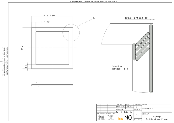
Both horizontal axes can be calibrated with two values: track offset and overall scaling. To find out how this is done, let's have a look at a part specially designed to find out those values:
It's a frame, similar to the one you use to put pictures up onto the wall. The essential part here is, it has long and short distances to measure on the same part. We need to measure both, to distinguish between track offset and scaling.
To the right of the drawing, a few tracks laid down by the extruder are sketched in. It shows how the track offset lets the extruder move closer to the inside of the part, so the outer side of the track just ends where the part should end as well.
All the sizes are overlaid by scaling, which is sort of a "gear ratio" between measurement units and stepper motor steps.
With that knowledge, we can sum up what the extruder moves to get the size T = 10 mm exactly 10 mm wide:
- <math>\begin{align}
\mbox{movement} = ( \mbox{intended size} - 2 * \mbox{track offset} ) * \mbox{scaling} \\ \end{align}</math>
This holds true for measurements of any size, i.e. also for the 100 mm size of our calibration frame:
- <math>\begin{align}
M_{10} & = ( 10\,mm - 2 * TF ) * S \\ M_{100} & = ( 100\,mm - 2 * TF ) * S \\ \end{align}</math>
You see? Two unknowns and two equitations, so the set is solvable.
... to be continued ... about how intended size differs from received size and about a formula to get scaling and track offset from measuring these 10 mm and 100 mm ...
Z Axis
On the Z axis, there is no track offset compensation, so calibration is reduced to scaling of part height. Build any part of 50 mm height, let it cool down, measure it. Then adjust your STEPS_PER_MM in your firmware's config.h to reduce the difference between intended and received part.
As most RepRaps use a threaded rod on the Z axis, the theoretical value should match reality pretty close. However, there's also material shrink as the plastics is printed at a higher temperature than room temperature.
Old Version of this Page
put here as the new part is still incomplete --Traumflug 22:55, 21 June 2011 (UTC)
Is this part of commissioning? Is this part of Builders/Config/Config Axes?
To calibrate, you will need the following: a Rep(st)rap, a slide caliper, and printing material (ABS, PLA, HDPE, etc).
You will also need this object file to print out.
- Setup and load your printing material.
- Print the calibration object.
- Allow the object to cool.
- Use the slide caliper to measure each edge and the diagonals.
- Make a note of each measurement and this will allow you to determine where a problem is IF there is a problem.
With the above measurements, you should be able to determine any alignment issues. The sides should measure withing .5mm of 40mm.
if it is off consistently, then it is probably a firmware issue.
Most inconsistent discrepancies are a sign of backlash (i.e. slop or play in your mechanical system). Make sure the grub screws on the pulleys are tight; make sure the belts are tensioned so that when you turn the stepper by hand, it immediately produces a movement in the axis; make sure all the bearings turn smoothly, and that the carriages only move along their intended axis. with all of that double checked, try printing your test piece again, and pay very close attention while it is printing. If your stepper motors make strange noises occasionally, it might be that they are skipping steps because they don't have enough torque. Try turning up the trim pot for that axis.
If all this fails, the best place to go to figure out how to fix your issue, once you've identified it, is either to ask someone in the forums, or on IRC, if you prefer. Then come back here and make this page better, or complain to the forum users.
Once you get a simple cube printed adequately, you might consider trying a more difficult object such as the bearing clip 01 for more fine-tuning.
