JennyPrinter minimalist
Release status: working

| Description | |
| License | |
| Author | |
| Contributors | |
| Based-on | |
| Categories | |
| CAD Models | ]
|
| External Link | []
|
Contents
- 1 Overview
- 1.1 . Preparations Before Installation
- 1.2 . Assembly of X&Y Stage
- 1.3 . Assembly of Frame
- 1.4 . Assembly of Z Stage
- 1.5 . Iinstallation of Circuit
- 1.6 . Safety Confirmation before Power On
- 1.7 . Function Test
Overview
. Preparations Before Installation
Tools
Rubber Hammer; Hexagon Wrench;Tweezers;Electrical Adhesive Tape;Scissor;Multimeter; Solid Gum;Lubricating Oil/Grease
Bill of Materials
. Assembly of X&Y Stage
Materials (P/N & Q'ty)
| Part Name | Q'ty | Unit | Specification |
| Ball Bearing | 8 | pcs | 8mm (ID) |
| Top Plate | 5 | pcs | Alu-Plastic Panel |
| Limit Switch | 2 | pcs | |
| 8mm shaft | 4 | pcs | 2 Long Shafts Plus 2 Short |
| 3*16 Screw | 16 | pcs | 16mm |
| Nuts | 16 | pcs |
Assembly Procedure
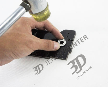
Assembly of Ball Bearing
Put the Ball Bearings in the countersunk holes on the front, left, right and backplate. Make sure you do not damage the dibont
and plexiglass plates. This is a total of 8 Bearings.

Assembly of Top Frame
Orientation Diagram for Assembly:


Assembly the real plate and top plate and fastened with screws. Assembly the front and top plate and fastened with screws.
400px 400px
Assembly the left plate and fastened with screws Assembly the right plate and fastened with screws, then the top frame is completed.
400px 400px
Assembly of Limit Switches for XY-Axle
As shown in figure limit a installation, pay attention to write down the color, the blue and white for the X axis (minimum) limit, limit (maximum) of red and white for the Y axis.
| Part Name | Q'ty | Unit | Specifications |
| 2.5mmScrew | 4 | pcs | 16mm |
| Nut | 4 | pcs |
400px 400px
Assembly of XY Axles
"Attention" in this step often dazzled installed wrong, cause the removed to return again. So carefully controlled images well, confirm that the direction of each part and proceed to the next step.
Position placed in the following figure, there are three holes behind the Panel, placed in your direction. Location described in this section will be used in accordance with the directions, is not the location of the machine.
Assembly of Left Axle
Prepare materials:
| Part Name | Q'ty | Unit | Specifications |
| White plastic mat columns | 1 | pcs | 5mm Length |
| White plastic mat columns | 1 | pcs | 10mm Length |
| Synchronous wheel | 3 | pcs | 8mm Inner diameter |
| Slider | 3 | pcs | |
| Shorter timing belt | 1 | pcs |
Insert a long 8mm the optical axis in the left rear bearing bore, and in a plastic mat in the figure order column, wheel and slider in the 8mm.
600px
600px
Once again check the figure below for synchronous wheel direction pad column position.
Then the wheel tighten the screws on both ends, attention: before tighten the screws, as shown in figure, hands are used at both ends of the wheel moves two to resist bearing guarantee will not become loose or shift of the optical axis.
600px
600px
Tighten the screws need to be turned with his hand after the optical axis, check whether the rotation axis resistance, if bad need to adjust again to install the optical axis.
700px

This completes Assembly of a shaft, we recommend doing beneath each shaft is rotated manually after the installation is complete the optical axis. Determine the resistance, try to find
and fix problems during Assembly. Avoid debugging adversely.
Assembly of Right Axle
Prepare materials:
| Part Name | Q'ty | Unit | Specifications |
| Slider | 1 | pcs | |
| Synchronous wheel | 2 | pcs | 8mm Inner diameter |
| 25mm White plastic mat columns | 1 | 个 | |
| 5mm White plastic mat columns | 1 | pcs |
Another longer 8mm shaft into the bearing and the slider, wheel and white plastic pad column mount light in turn, note that at this point, right when the wheel is installed, it is necessary
to install the timing belt on the left side mount together, also needs to be confirmed on both ends of the belt are located in the synchronization gear. As shown in the figure
450px 450px
As with left installation, hands are used at both ends of the wheel moves two to resist bearing guarantee will not become loose or shift of the optical axis, tighten the screws, rotation
axis by hand and observe whether the axis resistance, rotate correctly, if not then adjust again to install the optical axis.
450px 450px
Assembly of "Top" Axle
Prepare materials:
| Part Name | Q'ty | Unit | Specifications |
| Double wheel | 1 | pcs | |
| Synchronous wheel | 1 | pcs | 8mm The inner diameter |
| 10mm White plastic pad column | 1 | pcs | |
| Small timing belt | 1 | pcs |
To insert the shaft bearings, follow into the slider, wheel timing belt and a white plastic pad column, notice that, when installing the upper axis, set the left-right
axis slider in the upper timing belt mounted on the optical axis of the wheel, shaft through the hole positions on the slider in Figure
400px 400px 400px
Hands are used at both ends of the wheel moves two to resist bearing guarantee will not become loose or shift of the optical axis, tighten the screws, rotation axis by
hand and observe whether the axis resistance, rotate correctly, if not then adjust again to install the optical axis.
400px 400px
Assembly of "Bottom" Axle
Prepare materials:
| Part Name | Q'ty | Unit | Specifications |
| Synchronous wheel | 1 | 个 | 8mm Inner diameter |
| Plastic pad column | 1 | 个 | 10mm Length |
To insert the shaft bearings, follow into the slider, wheel timing belt and a white plastic pad column, notice that, when you install the lower shaft, also need to be
left-right axis slider in the upper timing belt mounted on the optical axis of the wheel, shaft through holes in the sliding block
400px 400px
Hands are used at both ends of the wheel moves two to resist bearing guarantee will not become loose or shift of the optical axis, tighten the screws, move the left slider
by hand and observe whether the axis resistance, rotate correctly, if not then adjust again to install the optical axis.
400px 400px
Adjustment & Calibration of X/Y Axle
Adjust the left and right side of the slider, the edge, two sliders and a side of a uniform space, ensure that on the same line.
If the slider is not on the same line, need to adjust the position, method: release one end fixed on two wheel screws on the optical axis, and then move the left slider, enables the slider located on the same line.
Confirm when finished, tighten the wheel screws again.
Adjust the slide block on, such as left and right sliders to adjust the same, loosen the wheel screws on the end around the optical axis. Then move the falling blocks on repositioning, as shown in the following figure
Confirm when finished, tighten the wheel screws again.
. Assembly of Frame
Assembly of Extruder
使用材料:
| Part Name | Q'ty | Unit | Specifications |
| 50mm Screw | 4 | pcs | |
| Gasket | 4 | pcs | |
| Extruder | 1 | pcs |
Use tools to remove the bottom of the extruder screw, use the screw extruder installation location on the diagram, note extruder installation directions.
Assembly of Base Plate
使用材料:
| Part Name | Q'ty | Unit | Specifications |
| The bottom frame | 5 | pcs | |
| 16mm Screw | 10 | pcs | 16mm Length |
| Nut | 10 | pcs |
Use 16mm screws to 5 floor mosaic, when you press the map display, sorted first and then left,
Assembly of Limit Switch of Z Stage
Materials
| Part Name | Q'ty | Unit | Specification |
| Limit switches | 1 | pcs | |
| 15mm Screw | 2 | pcs | 15mm length |
| Nut | 2 | pcs | 2.5mm Inner diameter |
The limit switches are installed in the location
Assembly of Aluminium Profile
Material: aluminum corner *4 screw M3x15
| Part Name | Q'ty | Unit | Specification |
| Aluminum corner | 4 | pcs | |
| 12mm screw | 15 | pcs | 12mm length |
According to the following diagram to install aluminum angle on the base and tighten the screws, pay attention to the placement of angle aluminum, aluminum angle at both ends of the location. Angle aluminum corners and there may be a slight deviation, needed a little squeeze.
Assembly "Base Plate" Module and Top Module Together:
Materials:
| Part Name | Q'ty | Unit | Specification |
| Upper part of the frame | 1 | pcs | |
| Lower part of the frame | 1 | pcs | |
| 12mm Screw | 16 | pcs |
Four aluminum corner into the top frame, you may need to slightly adjust the extrusion and then tighten the screws. After the completion of transfer modes and opacity
Assembly of Stepper Motors for XY-Axle
使用材料: 步进电机*2 20mm螺丝*4 垫片*4 10mm不锈钢垫柱
| Part Name | Q'ty | Unit | Specification |
| Stepping Motor | 2 | pcs | |
| 25mm Screw | 4 | pcs | |
| Gasket | 4 | pcs | |
| 10mm Stainless steel pad column | 4 | pcs |
Use screws, and stainless steel pad column stepper motors are installed in the following location, note this loading step machines need to be small timing belt mounted on the optical axis stepper motor in the synchronization gear, when you screw on, do not tighten, stepping motor position needed to be adjusted to exactly synchronous with clamp in position and tighten the screws again.
Assembly of Nozzle
| Part Name | Q'ty | Unit | Specification |
| Heating nozzles | 1 | pcs | |
| 6mm Optical axis | 2 | pcs | A long and A short |
First use of optical axis into two 6mm linear bearings, nozzle figure placed on the printer again, note that a. shorter axis vertical to the optical axis of the
graph location, placement of optical axis cannot be reversed. B. the nozzle cannot be reversed.
Slide the optical axis figure pressed into blocks, pay attention to do not too much force so as not to bend the ends of the optical axis, note the horizontal axis in
the left part of the length you want, touch the limit switch.
Use the same method to install vertical to the optical axis, note, note when installing the vertical to the optical axis, due to the transverse axis has been fixed,
could lead to vertical to the optical axis is more difficult to install, users can adjust the horizontal and vertical to the optical axis so that the installation,
users need the patience to install, please ensure that the optical axis fixed.
White feed the other end into the top of the extruder hole
. Assembly of Z Stage
4.1 Platform base
Flange linear bearing flange screw *1 nut *8 25mm *2 test *1 10MM motor nut screws *4
| Part Name | Q'ty | Unit | Specification |
| Flange linear bearings | 2 | pcs | 12mm Inner diameter |
| Flange nut | 8 | 个 | |
| 20mm Screw | 1 | pcs | 25mm length |
| Try motor nut | 1 | pcs | |
| 10mm Screw | 4 | pcs | 10mm length |
Below: a. Use screws on the flange linear bearings on z axis platform (in this case not just screws tightened), b. 25mm screws to mount the platform left empty, c. try pole motor nuts are fixed to the platform,
400px Note the platform opposite direction
4.2 Platform baffle installation
Using platform*1 bezel nut*2
| Part Name | Q'ty | Unit | Specification |
| Platform bezel | 1 | pcs | |
| Nut | 2 | pcs |
4.2-1 Remove the bezel, folded pattern:
4.2-2 The nuts into the holes in the bezel,and screws using the tape, so as not to fall off.
4.3 Axis column
Use 12mm axis *2 motor *1
| Part Name | Q'ty | Unit | Specification |
| 12mm Optical axis | 2 | pcs | Diameter 12mm |
| Screw motor | 1 | 个 |
Axis screw machine, bezel as figure into the platform shell, then mounted the platform by holes, pay attention to rod motor is test thread, manually rotate the mount.
4.4 Z-axis limit switch installation
15mm screw *2 nut *2
| Part Name | Q'ty | Unit | Specification |
| Limit switches | 1 | pcs | |
| 15mm Screw | 2 | pcs | |
| Nut | 2 | pcs |
Position mounting limit switches at the bottom, as shown in Figure
4.5 Motor wire connection
| Part Name | Q'ty | Unit | Specification |
| Stepping Motor line | 4 | pcs |
Use stepping motor line connected to the extruder, XY and z axis motor shaft on the motor and limit switch at the bottom line and x-axis stepper motor wire into the Groove of the bottom step test will be pushed into the bottom of the motor, using the screws from the bottom plate fixed on the other side try pole step motor.
4.6 平台安装
Using white plastic mats *2 screw *6 locking-nuts 12mm *4
| Part Name | Q'ty | Unit | Specification |
| White plastic spacer | 2 | pcs | Prints |
| 12mm Screw | 6 | pcs | |
| Self-locking nut | 4 | pcs |
4.6-1 Put the gasket in position on the map, and use the self-locking nuts and screws at both ends to the optical axis,
4.6-2 Put the machine, and then tightening up the screws on the flange linear bearings and screws from the holes at the bottom of mount will hold the bezel.
400px 400px
4.7 Hot bed installation
Using a hot bed*1 spring*3 platform nut*3
| Part Name | Q'ty | Unit | Specification |
| hot bed | 1 | pcs | |
| spring | 3 | pcs | |
| platform nut | 3 | pcs |
Hot-bed placed in the platform, and springs in hot screw at the bottom of the bed, three screws have to be placed on the hot bed springs.
. Iinstallation of Circuit
Materials:Circuit Board
5.1 Power connector and switch installation
Use Switching *1 power supply interface *1
| Part Name | Q'ty | Unit | Specification |
| Switching | 1 | pcs | |
| power supply interface | 1 | pcs |
Put switch on and the power connector into the base as in the figure, check power connector wiring, power has a digit, 12 negative and 34 positive, cannot make a mistake.
400px 400px
400px 400px
Power interface switch red cable (one side is positive is negative), as shown below
5.2 Put wear out the screws from the bottom holes, put on white plastic pad column and switch and power interface yellow cable connected to the circuit board in the below order, notice cannot be wrong here, otherwise it will burn out element. Board polarity, plus or minus plus or minus respectively from right to left, using the self-locking nuts to the circuit board fixed the following figure
5.3 Circuit wiring
Hot bed of chart position into two red lines in circuit boards, no distinction between positive and negative.
And then head of the two red lines on the Access Board, there is no distinction between positive and negative, as shown below:

And then head of the two red lines on the Access Board, there is no distinction between positive and negative, as shown below:
Blue and white circuit board on the spray nozzle, pay attention to two white lines here the nozzle cannot be mistaken, the blue line is positive, the white line for cathode do not wrong.
Will head red and white lines connected to the circuit board, the red line is positive, the white line is negative, as shown in figure.
The x axis limit switch connected to the circuit board, note that here to require users to identify the x axis, y axis and z axis limit switch wires. When a printer is to place, move up and down the z axis of the platform, sprinklers, vertical y axis, sprinklers lateral movement for the x axis. Installation on the roof at the top limit switch the limit switch for the x-axis, side plate for the y axis on the limit switch.
Put the nozzle in hot temperature-sensing line access circuit, as shown in Figure
X y z circuit of stepper motor and extruder, pictured below, note below in order from right to left in order for the x axis, y axis and z axis extruder. Here required the user to judge for themselves the x axis, y axis and z axis and wire extruder. When a printer is to place, move up and down the z axis of the platform, sprinklers, vertical y axis, sprinklers lateral movement for the x axis. Installed at the top back of the extruder.
Screen to access the circuit board
5.4 The installation screen
Take out the screens using the self-locking nuts installed in the lower chart position, and will wear out in the line up from the bottom of the screen holes, attention please carefully screen line through the hole to avoid screen cable is damaged.
400px 400px 400px
Last access lamp with as figure will lamp with posted into figure in the angle aluminum inside, will lamp with line from base hole bit in the through, note here needed note lamp with power line of location, user posted lamp with Qian please first judge lamp with power line placed location, if location placed improper may led to power line length insufficient, cannot access circuit board, lamp with plus or minus very also cannot received wrong, user needed view lamp with interface at plus or minus mark, circuit board wiring following, note circuit board power out plus or minus very, by Shang to Xia respectively for negative plus or minus are.
. Safety Confirmation before Power On
6.1 Check whether the power supply polarity.
6.2 Fan polarity is reversed.
6.3 Check motor drive module installed.
6.4 There is no short circuit where the touch line, there are no exposed wires and connectors.
After you confirm the above 4 points no problem, you can plug in the machine, and turn the power on.
. Function Test
7.1 Boot to normal, the screen displays correctly. 400px
7.2 LED lighting OK
7.3 Temperature OK
7.4 Nozzle cooling fan (behind the head) operation OK
7.5 Nozzle heating OK
7.6 Hot bed OK
7.7 Models cooling fan (left side) OK
7.8 Back to the original point OK
7.9 E-axis extruder movement OK
7.10 USB online OK
7.11 SD card reader OK