Prism
This page is a development stub. Please enhance this page by adding information, cad files, nice big images, and well structured data!
Release status: Experimental

| Description | Mendel Frame
|
| License | unknown
|
| Author | |
| Contributors | |
| Based-on | |
| Categories | |
| CAD Models | |
| External Link |
Contents
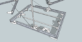
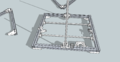
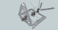
Prism Mendel

This extruded aluminum frame is a quick upgrade to your standard Sells Mendel. It makes it cleaner, more open and, more importantly, more rigid.
You can start printing parts today, but wait to order parts 'till next week while I finalize a screw/nut count. If you just can't wait. know that I've used less than 100 screws/t-nuts for my build, but over 100 M4 washers.
The only part i don't have designed yet is a mount for the endstops. You can use the endstop holder designed for Prusa, or run without endstops while i design one for 20x20 mounting, or design one yourself and put it up here or on thingiverse.


design goals
I've always disliked how parts of the Mendel jut out. it's a minor complaint, but one I wanted to address as I moved to extruded aluminum. The Z rods are now inside the 'triangle', as is the z motor and y motor. The x axis can still jut out, but how much really depends on which x axis you choose, which isn't really part of this mod. It is much easier to travel with the Prism or make a case for the Prism because of this change. It also just makes the printer build area seem more open and accessible.
Another thing I want to try in the future is making a tent out of Mylar. The tent would hold in the heat from a heated bed and hot end and block errant air currents, but wouldn't get as hot as a heated chamber so overheating motors hopefully won't be a problem. This is going to be much easier to try with the Prism.
In addition, the y and z motors are in direct contact with the aluminum frame, which should dissipate motor heat nicely.
Unfortunately, for people who like Prusas, the frame won't allow top mounted motors as is. I think moving the motors to the base and using gears to drive the z lead screw is a good workaround if you still want two motors, but belt routing and tensioning is much easier with the Prism, so it might make a Sells-style single motor/belt more attractive again. Either way, a gear driven system also allows other gear ratios and takes care of the shaft coupling issue. However, if you prefer a pure Prusa, the MendelMax is a great alternative.
Another benefit of the Prism is a much larger Z build area(20-60 mm, hard to be precise because it depends mostly on your extruder and x axis) since the Y rods now sit below the bottom end of the Z rods. My Prism is 210mm from the bed to the X rods at ~Max Z, and all of this area is printable because the carriage will not hit the frame rods anymore. The x and y can also be increased, potentially.
Finally, most extruded aluminum profile suppliers cut to size for no extra cost, and the cuts are much more precise than you would get with a hacksaw at home. It's a nice extra that should make assembly and calibration easier.
New non-printed parts
(Misumi parts numbers are listed, where applicable, for easy ordering)
- Extruded Aluminum Profile
- 20x20x400 - 9 (HFS5-2020-400)
- M3
- M3x10mm SHCS - ~10-20
- M3 Nut - ~10
- M4
- M4x12mm SHCS - ~70
- M4 T-Nuts (which are compatible with your extrusion) - ~70 (HNKK5-4)
- M4 washer - ~140
- NOT REQUIRED M4 Post-Assembly T-Nut - 20 will run about $10 - makes it easy to attach parts without having to disassemble the whole frame. (HNTA5-4)
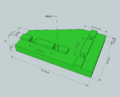
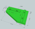
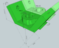
Printed Parts
Files
The .Stls for the 60 inside part and Ztop bracket print two pieces at once.
The most up-to-date files will be on github: https://github.com/Buback/Prism-Reprap
Images
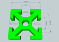
Print 6
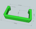
Print 3 (6 pieces)
Print 2
Print 2
Print 1
Print 1
Print 6
Print 1 (2 pieces)
Print 1
Print 1
Print 2
Print 1
Just for reference


Optional pieces:
To secure wires in the extrusion channels

Build Instructions Notes
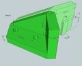
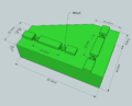
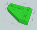
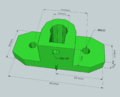
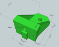
The Thick 90 degree part is just to raise the printer up high enough so the z rods and motor shaft don't hit the table/workbench your printer is upon. You can use the thin part for all the vertexes but you're going to need to add many, many extra washers, because either way, you'll need m4x20 screws. I'm sure somebody will come up with a better solution eventually. --Buback 18:24, 27 December 2011 (UTC)
Visual Assembly Guide
I removed my old instructions, as I think the pictures bellow are clearer, but i'll add detailed instructions over the next couple weeks --Buback 17:58, 28 December 2011 (UTC)

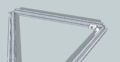
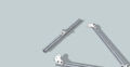
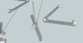
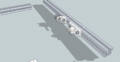
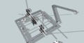
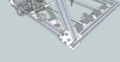
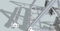
All the extrusions touch at the corner, forming an equilateral triangle
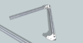
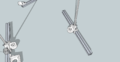
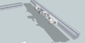
Begin by loosely attaching the Ztop piece to two extrusions. Be careful and don't flex this part, as it's not strong enough on it's own

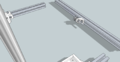
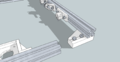
Add the first 60 end piece. Make sure the extrusion corners are touching as you tighten down the screws. Once you have the 60 end plate secured, you can screw down the Ztop screws

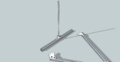
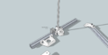
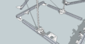
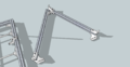
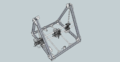
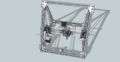
The assembled A frame
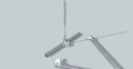
The other side is the same, except without the motor bracket or endstop holder. Also assemble the other A frame. Remember to put the smooth rod holders with the screws facing out
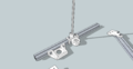
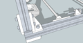
Use M4x20 screws on the thick 90 deg parts

Attach the other 90 deg pieces to the other extrusion

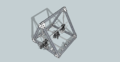
Attach the Y motor bracket
The Y rods can be removed later to put on the a Y carriage, but you'll want the t-nuts in the slots now. You will also need to slide t-nuts into a channel for the bottoms of the A frame 60 deg pieces
Add your X axis of choice now
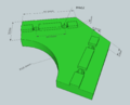
Add all the 60 deg inside corners
Slide a t-nut on each side for the unattached end of the 60 inside part, and then ease the Z smooth rod into the Ztop bracket as you lower the A frame onto the base. screw the 60 end part securely on both sides.
Screw in the 60 inside pieces securely
Now do the other side A frame
Assemble the top crossbar by attaching the two 90 deg thin pieces to each side. also add t-nuts for the top 60 deg inside pieces.
Slid the top bar into place and secure all the screws
Congratulations! You're done! (except for the belting and all the wiring, etc.)


Further Development
-There isn't room at the top of the z rods to get a tool in and tighten the screws, which is why you need to put in the z rod first. I'm not pleased with this, and so the first order of business is to figure out a way to fix this. Adding longer 'arms' to the Ztop piece is the obvious solution, but then it's a longer unsupported angled print, which i feel leads to week parts. the other option is to split the part down the middle and make it two parts. the problem here is alignment becomes a bit of an issue, potentially. Anyway, if you'd like to design a part that holds a 8mm (or larger) rod in between two 20x20mm extrusions at a 60deg angle, feel free to post it here.
-Perhaps a dedicated Y and x carriage would be nice. I prefer a vertical X and ball bushings. The X build area could also be made bigger, but is now limited by the x length of the x carriage, and not by the space between the angled bars.
-Fully Parametric parts, a la OpenSCAD.