Prusa Mendel
This page is a development stub. Please enhance this page by adding information, cad files, nice big images, and well structured data!
Release status: working

| Description | Prusa Mendel is simpler remix of normal Mendel.
|
| License | |
| Author | |
| Contributors | |
| Based-on | |
| Categories | |
| CAD Models | |
| External Link |
Also see SAE Prusa Mendel if you are building this machine using SAE (Imperial) Fasterers
The Prusa Mendel is a simpler remix of the original Mendel. I wanted to use bushings instead of regular bearings. The current prototype is using two bearings in total, one for X and one for Y axis.
I have the entire machine up and running, with my printed PLA bushings. It's pretty smooth.
<videoflash>tyVM3-v84I0</videoflash>
Contents
Development
The development of the Prusa Mendel is hosted on github: http://github.com/prusajr/PrusaMendel
You can follow the changes on Changelog
You can sign up for github for free and fork the project to begin working on it.
History
Bill of Materials
The Prusa Mendel BOM is documented here. Please do not use the BOM on github as it is not updated as regularly.
(in works, not complete yet)
Printed Parts
6x frame-vertex RP
OR
4x frame-vertex with foot RP
2x frame-vertex      RP
2x coupling           RP
3x endstop-holder     RP
1x x-carriage         RP
1x x-end-idler        RP
1x x-end-motor        RP
1x y-motor-bracket    RP
2x z-motor-mount      RP
4x belt-clamp         RP
8x bar-clamp          RP
2x rod-clamp          RP
2x pulley             RP
Printed Bushings
12x pla-bushing RP-PLA (check your build file, the file makes either 4 or 12.)
Guesstimate of other parts: ("vitamins") (verified)
70x M8 nut            Fastener
80x M8 washer         Fastener
3x 608 Bearing        Bearings
 6x M8x370mm Stud side       Threaded rod
 4x M8x294mm Stud end        Threaded rod
 3x M8x440mm Stud top, Z bottom        Threaded rod
 2x M8x210mm Z-Leadscrew     Threaded rod
 2x 8mmx495mm X-bar           Smooth rod
 2x 8mmx406mm Y-bar           Smooth rod
 2x 8mmx330mm Z-bar           Smooth rod
 1x 225mmx225mm Print bed      Thick Sheet
 1x 140mmx225mm Print bot.     Thick Sheet
(unverified)
 3x ??? Optoflags          Thin Sheet
20x M3x?? for motors+pul.  Fastener
16x M3 washer "  "         Fastener
10x M3x10 for X-ends Fastener
 8x M4x15 for X&Y-belts    Fastener
16x M4 washer "  "         Fastener
 8x M4 nylock "  "         Fastener
 3x M4x?? for X&Y-bearings Fastener
 6x M8x30 Mudguard/fender washers Fastener
16x M4 nylock "  "         Fastener
 4x M4x?? for Z-Clamps     Fastener
 8x M4 washer "  "         Fastener
 4x M4 nylock "  "         Fastener
 4x M4x30 for Print bed    Fastener
 ?x M? washer "  "         Fastener
 ?x M? nylock "  "         Fastener
1x standard Mendel extruder
 5x Nema 17                NEMA Stepper
 1x standard Mendel electronics or Mendel alternative electronics.
(The Prusa Mendel uses the 4 drivers in the standard Mendel electronics package to drive 5 motors by using "two steppers wired in parallel to one driver"[1]).
Printed Parts

Printing a Prusa on a Mendel
An easier option then individually printing each part if you are printing Prusa on a RepRap Mendel is the pre-assembled build file containing the Prusa parts. With this option you only need to print the Mendel plate and the PLA bushings to get a complete Prusa Mendel:
- Mendel Plate (contains all printed parts except the PLA Bushings)
- PLA Bushing
Printing a Prusa on a CupCake CNC
There are also pre-assembled build files available to fit your CupCake CNC's build area (download using right click => save as)
Note:
- These plates use the full surface of the build platform, so remove bolts if necessary.
Plates for the MakerBot:
- Makerbot Plate 1=> 6 hrs 30 min
- Makerbot Plate 2=> ~2 hrs 30 min (needs retesting)
- Makerbot Plate 3=> 5 hrs 40 min
- Makerbot Plate 4=> 2 hrs 30 min
- Makerbot Plate 5 => 1 hr 50 min
Printing a Prusa on anything else
Last but not least, if you have a machine that doesn't fit into any of the previous options all the .stl files necessary to print a Prusa Mendel are available on the PrusaMendel Github where you can download them and print them individually.
Assembly
This section is work in progress.
Assembling the frame
Assembling the frame vertex triangles (2x)
There is a triangle on each side of the Prusa RepRap, you will need to make 2 of these and then connect them together (see next step) to form the Prusa frame. Each side is an equilateral triangle with a frame vertex on each corner. You can use either footed or non-footed vertices to build this (the footed ones look better, but are not critical.) The instructions assume you are using footed vertices.
Parts Required (per triangle)
- 2 RP footed frame vertices
- 1 RP frame vertex (non-footed)
- 1 RP bar clamp
- 3 370mm M8 threaded rods
- 14 M8 nuts
- 14 M8 washers
- (optional but recommended)A piece of threaded rod or wood or any other material with precisely 290mm length. This is your frame jig J1.
Instructions
- Take one of the 370mm threaded rods, and slip an M8 washer onto the middle of it.
- Take the RP bar clamp (the U-shaped bit with the two holes) and slide the threaded rod through the two holes until the clamp sits next to the washer.
- Slide another washer onto the rod from the other side.
- Thread two M8 nuts onto either side of the clamp, until they are next to the washer, but do not tighten them yet.
- Thread another two nuts on each side of the rod, followed by washers. See the picture for what it should look like. <flickr>5188262096|thumb|right|m|The bar clamp on the threaded rod.</flickr>
- Slide the rod through the long bottom (footed) side of two vertices. Make sure the feet point in the same direction. Also make sure the bulge on the non-footed side of the vertex points outwards.
- Measure the distance. The distance between the two vertices should be 290mm (along the rod). Get it approximately right now, we will check this again later. If you have a frame jig, place it between the two vertices and adjust the nuts until you can just barely fit the jig J1 between them.
- Place another washer and nut on the other side of the vertex. Tighten, but not too much. We'll need a bit of flexibility here still.
- Take another 370mm M8 threaded rod and place a nut followed by a washer at each end.
- Place one end of the threaded rod into the one of the two footed frame vertices. It should be in the same plane as the first threaded rod. fix it in place with a washer and nut. You should now have two sides of the equilateral triangle.
- Take the third piece of threaded rod and put a nut and washer on each end. Place it in the other footed vertex and fix it in place with a washer and nut. You should now have a triangle of threaded rods with two footed vertices on two of the corners, nothing in the third corner, and a bar clamp between the two vertices.
- Take the third vertex (non-footed) and slide it onto the threaded rods in the final corner of the triangle. Measure the lenghts of the three sides to make sure they are all 290mm long (along the rod from plastic part to plastic part). Adjust the nuts to make sure this is so. Use the frame jig J1 if you have one. Once done, place a washer and nut on the top of the vertex. Tighten all the outer nuts.
- You should now have a sturdy triangle with equal-length sides, two feet on the bottom, and a bar clamp between the feet. Adjust the nuts around the bar clamp (but do not crush the bar clamp together yet) until it's approximately in the middle of the rod. Leave the nuts there loose. See photo for what you should have at this point. <flickr>5188259098|thumb|right|m|The finished frame triangle </flickr>
- That's it, that's one of the triangles done. Repeat the entire procedure for the second triangle. It is exactly identical to the first.
Now we need to connect the 2 frame triangles to form the Prusa RepRap frame.
The easiest way to do this is to thread everything onto the front and rear threaded rods and attach those to the triangles first, and then thread the top rods through. That's what the instructions below assume you are doing.
Assembling the front threaded rods
These 2 threaded rods are used to connect the front/bottom vertex of each triangle as well as the y-stage bars and y motor mount to the frame.
Parts Required
- 2 assembled frame vertex triangles
- 2 RP rod clamps
- 1 RP y motor bracket
- 16 M8 nuts
- 17 M8 washers
- 2 M8x30 fender/mudguard washers
- 1 608 bearing
- 2 294mm threaded rods.
Instructions
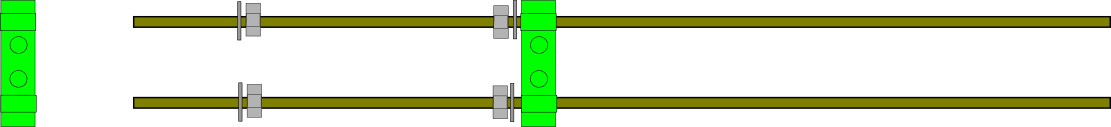
- Thread the bottom rod first. Thread an M8 nut onto the middle of the rod. Slide an M8 washer next to it.
- Thread the rod through the bottom hole of the RP y-motor-bracket. The bottom hole is the one with the odd-shaped (not circular) hole next to it.
- Slide another washer onto the other side of the rod and add another M8 nut to hold it in place.
- Add a nut and washer to each end of the rod.
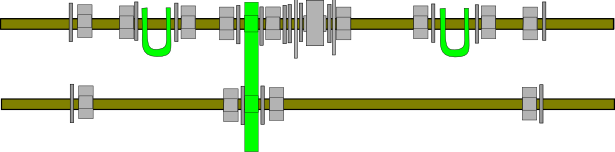
- Now thread the top rod. This is a complicated one, so make sure you get it all done in the right order. From left to right, the rod should have: 1 washer, 2 nuts, 1 washer, 1 rod clamp (threaded through the holes), 1 washer, 2 nuts, the y-motor-bracket (with the circular hole pointing towards you), 1 fender/mudguard washer, 1 washer, 1 608 bearing, 1 washer,1 fender/mudguard washer, 2 nuts, 1 washer, 1 rod clamp (threaded through the holes), 1 washer, 2 nuts, 1 washer.
- When you hold it with the bigger part (with the circular hole) of the motor bracket towards you, it should look like the picture below. Verify this now.

- You can now attach this setup to the triangle sides. Make sure the bigger part of the motor bracket points OUT of the triangle. Thread the ends of the rods through two of the footed vertices. Put a washer and nut on the end of each threaded rod.

Assembling the rear threaded rods
These 2 threaded rods are used to connect the back/bottom vertex of the 2 triangles together as well as the y-stage bars and belt pulley.
Parts Required
- 2 assembled frame vertex triangles
- 2 RP rod clamps
- 14 M8 nuts
- 14 M8 washers
- 2 M8x30 fender/mudguard washers
- 1 608 bearing
- 2 294mm threaded rods
Instructions
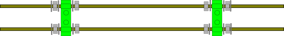
- Thread the bottom rod first. Add a nut and washer to each end of the rod.
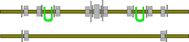
- Now thread the top rod. This is again a complicated one, so make sure you get it all done in the right order. From left to right, the rod should have: 1 washer, 2 nuts, 1 washer, 1 rod clamp (threaded through the holes), 1 washer, 2 nuts, 1 fender/mudguard washer, 1 washer, 1 608 bearing, 1 washer,1 fender/mudguard washer, 2 nuts, 1 washer, 1 rod clamp (threaded through the holes), 1 washer, 2 nuts, 1 washer.
- It should look like the picture below. Verify this now.
- Attach the two rods to the two remaining footed vertices. Thread each end of the rod through the vertex, and add a washer and nut. It should now look like this:
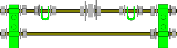


Your frame should now be standing on its own feet without support, but the tops sides of the triangles will still be wobbly. We'll fix that next.
Assembling the top threaded rods
These connect the 2 frame triangles at their tops as well as providing mounts for the z-axis motors.
Parts Required
- 2 assembled and connected frame vertex triangles
- 2 RP z motor mounts
- 12 M8 nuts
- 16 M8 washers
- 2 440mm threaded rods
Instructions
- Slide one of the threaded rods through one side of one of the top vertices. Put a washer, two nuts, and another washer on the part of the rod between the top vertices. This is what it should look like when seen from above:
- Repeat for the other rod. It should now look like this:
- Slide the rods through the opposite side vertex. Thread the nuts up to the vertices on each side.
- To each of the four ends of the threaded rod, add a washer, a nut and another washer. Your setup should now look like this:
- Take one of the RP z motor mounts and attach it to the ends of the threaded rod. The side with the two holes and the indentation should point towards the outside. Add a washer and nut to the end of each rod.
- Repeat this on the other side. The top of the machine should now look like this:


Tightening the frame
Now that the frame is fully assembled we can adjust and tighten each of its threaded rods. You will need your frame jigs if you have them, or a reasonably precise length measurement tool.
Parts Required (per triangle)
- 2 RP bar clamps
- 4 M8 nuts
- 4 M8 washers
- 1 440mm threaded rod
- (optional but recommended)A piece of threaded rod or wood or any other material with precisely 290mm length. This is your frame jig J1.
- (optional but recommended)A piece of threaded rod or wood or any other material with precisely 234mm length. This is your frame jig J2.
Instructions
- Verify that the triangle vertices have distance J1 (290mm) from plastic to plastic along each of the three sides. Once you are sure of this, tighten the outer vertex nuts until they are firmly attached and unable to move, but do not crush the plastic parts.
- Adjust each of the bottom rods until it has distance J2 (234mm) between the inside ends of the vertices. Use frame jig J2 to check this if you have it. Once you are sure this is true, tighten the outer vertex nuts until they are firm, but do not crush the plastic.
- Adjust the top of the frame so that the distance between the inside ends of the vertices is precisely J2 (234mm) and the length of rod outside the vertex on one side is the same as the length outside the vertex on the other side. Double-check the distances before tightening the nut on the outside of the vertex.
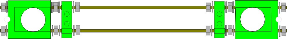
- The frame should now be fairly stable. Using a plumb line or similar (for example a nut hanging on a length of yarn), adjust the bar clamps on the bottom side of each triangle until they are directly below the middle of the top vertices. Do not tighten the nuts either side of the bar clamps yet.
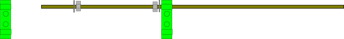
- Insert the 440mm threaded rod through the two rod clamps on the bottom of the frame. make sure the new rod is on top of the triangle bottom rod. Adjust it so that the same length sticks out on each side.
- On each side, place a nut, washer, rod clamp (threaded through the holes), washer, and another nut. The setup should look like this when seen from below:

Assembling the z stage
Parts Required
- 2 shaft couplers
- 2 PLA bushings
- 2 stepper motors
- 2 threaded rods (TODO: size)
- 2 smooth rods (TODO: size)
- 1 prusa frame (see previous step)
Instructions
Assembling the y stage
Parts Required
- 4 PLA bushings
- 1 belt clamp
- 2 smooth rods (TODO: size)
- 1 y timing belt
- 1 stepper motor
Instructions
Assembling the x stage
Parts Required
- 4 PLA bushings
- 2 smooth rods (TODO: size)
- 1 x timing belt
Media
- Two printers simultaneously - Prusa and shaper cube working side by side.
- Prusa homing using enstops
- Prusa development overview
- Prusa Y axis stress test
- Prusa Z axis stress test
- Early preview of the Prusa Mendel redesign
- Fumon's Prusa build session 1 - D1plo1d building Fumon's Prusa Mendel at Hacklab.to. Should give a hint as to how the Prusa Mendel parts go together.