RAMPS 1.2
Release status: Working

| Description | A RepRap etch resist printable circuit board that fits on the Arduino MEGA and holds interchangeable stepper driver carriers and the rest of RepRap's electronics.
Arduino MEGA based modular RepRap electronics.
|
| License | |
| Author | |
| Contributors | |
| Based-on | |
| Categories | |
| CAD Models | |
| External Link |
Contents
Summary
RepRap Arduino Mega Pololu Shield, or RAMPS for short. It is designed to fit the entire electronics needed for a RepRap in one small package for low cost. It is a "1.5 layer" designed board (i.e. it's double sided board, but one of layers can easily be replaced with wire-jumpers) that is printable on your RepRap with the etch resist pen method, or home fabbed with toner transfer. At the same time it is based on the powerful Arduino MEGA platform and has plenty room for expansion. The modular design includes plug in stepper drivers and extruder control electronics on an Arduino MEGA shield for easy service, part replacement, upgrade-ability and expansion. Additionally as long as the main RAMPS board is kept to the top of the stack a number of Arduino expansion boards can be added to the system.
Versions up to 1.25 can and have been printed with etch resist on a RepRap using a sharpie pen. Newer versions have temporarily given that design requirement for more features and to cover more edge cases.
This board is mostly based on Adrian's Pololu_Electronics and work by Tonok. Copper etch resists methods suggested by Vik. Also inspired by Vik's work with EasyDrivers. circuit design based mostly on Adrian's Pololu_Electronics Used Joaz's pin definitions for initial layout. Much inspiration, suggestions, and ideas from others in the RepRap community.
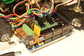
Mendel printed RAMPS wired to Mendel.
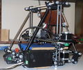
Mendel with RAMPS in enclosure mounted.
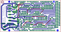
screen capture of 2-sided RAMPS layout
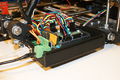
commercially fabbed 2-sided RAMPS wired to Mendel


Features
- It has provisions for the cartesian robot and extruder.
- Expandable to control other accessories.
- 3 mosfets for heater / fan outputs and 2 thermistor circuits.
- Fits 4 Pololu stepper driver boards
- Pololu boards are on pin header sockets so they can be replaced easily or removed for use in future designs.
- The pin headers for the stepper motor outputs are placed on top of the Pololu boards saving routing them on the main shield.
- I2C and SPI pins left available for future expansion.
- All the Mosfets are hooked into PWM pins for versatility.
- Servo style connectors are used to connect to the endstops, motors, and leds. These connectors are gold plated, rated for 3A, very compact, and globally available.
Safety Tip
Once you start putting electricity into your RepRap - even at just 12 volts - you have to take basic, common sense precautions to avoid fires. Just in case these fail, test your workshop smoke detector. Got no smoke detector? Get one!
Assembly Instructions
You can go here to see a visual build printthat blog
Following this guide I found it may be helpful to complete Step 29. "Make yourself four 1×4 header units." before Step 12. "Get out four 1X16 female headers." to give you more space when soldering.
Component Soldering
Shield Assembly
After using your preferred circuit board manufacturing method, it's time to solder on the components. Beginning solderers would find the task much easier if they were to work from the inside of the board to the outside, rather than using the current order below.
- Top wires. (This step is not required if using a two sided PCB) Make sure they are clear of other components to be soldered later
- Resistors as shown to the right.
- Small 100nF capacitor, C4
- LED - Positive(long lead) at the top, ground (Short lead) at the bottom.
- Cut the 2 row pin headers into 2x3 (6)blocks, 7 of them needed. Solder these for microstep selection jumpers, and endstop jacks. It is easiest to place all these and hold them in place with a card to flip board for soldering.
- Cut the 1x10 pin header to 4 pins long and solder it in the T1 T0 holes for thermistor jack. Solder one of the end pins first, straighten the pins to be perpendicular to the board and solder the rest of the pins.
- Four 1x16 socket headers into place for the stepper driver sockets. (If you have 1x20 socket headers, cut them down to 1x16)
- Pass-through headers that will connect the shield to the Arduino board (around the perimeter of the board). Can be later for short pin headers. This includes the one 2 x 18 Pin Stackable Female Header, the five 1 x 8 Pin Stackable Female Header and the one 1 x 6 Pin Stackable Female Header.
- More recent kits include 2x18, 1x22, and 1x24 pin headers for connection to the Arduino MEGA. Cut the 1x22 into 1- 1x6 + 2- 1x8 lengths. Cut the 1x24 into 3- 1x8 lengths. If you insert these into the Arduino MEGA to hold them straight while soldering, take care not to heat for too long risking melting the Arduino's connector.
- Solder the large capacitors, C6, the 100uF capacitor, C5, C8 10uF capacitor as shown lower right.
- They must be inserted in the correct orientation. + to the top for C6 and C5 or left for C8.
- Mosfets, Q1,Q2,Q3, the three N-channel Protected Mosfet, STP55NF06L
- They must be oriented in correctly (as per photographs)
- The big yellow MF-R500 fuse, F1.
- D1, the 1N4004 diode.
- The diode can be omitted, it may be needed in the future for printing from SD or USB. This will power the Arduino from the shields 12V input. Diodes must be oriented correctly. If you are using higher than 12V to power the shield you should omit the diode to prevent damage to the Arduino and stepper drivers.Warning: The high side of the stepper boards are designed to accept up to 35V, but if you do this the heater and other high side outputs will be at that voltage also. You may need to adjust the heater resistance, etc.
- Power connector, X1, the 2 pin fixed/pluggable terminal block.
- Screw terminal block, (6 pin)
- Reset switch, S1, push button switch
- Thoroughly check for shorts (This is crucially crucial for DIY etched boards.)
- Check for continuity between each and every pin to the pins next to them and GND, 12V, 5V (VCC).
- Set your meter to beep for continuity, hold a probe on GND and check all soldered pins. If it beeps check if it is supposed to be GND and contine. Repeat for 12V and 5V.


Stepper Driver Boards
- Jumpers need installed under each stepper driver:
 jumper   Yes/No  stepsize
 1     2    3
 no   no    no    full step
 yes  no    no    half step
 no   yes   no    1/4 step
 yes  yes   no    1/8 step
 yes  yes   yes   1/16 step
For now the default is 1/16 micro stepping (all jumpers installed under drivers)
- Cut the pin headers to 8 pins long so that they fit each side of the stepper driver.
- Insert the pin headers into the sockets on RAMPS
- Fit the stepper drivers onto the pin headers and solder. Only heat each pin for a few seconds at time to avoid damage to the socket.
- Version 1.2 has the stepper connector on the RAMPS shield and all the pin headers can go under the Pololu Stepper Drivers.
- Version 1.1 and older the power and control pins go down towards your new shield and the motor pins(1a,2b,2a,2b) on top of the board (component side) so the motors can be plugged directly in. (See image on right)
- Glue the heatsink to the top of the A4983/A4988 chip using the provided pad of double-sided adhesive.

Make the cables up for the opto endstops
- Cut the 26awg 3 conductor cable into 3 length.
- Note: you may want until you've built your machine to cut the cables to the perfect length.
- WARNING In order to keep the PCB at a printable resolution two wires have been flipped from the traditional opto endstop boards. The signal pin has been moved to the outside of the connector.
- Hooking these up incorrectly can damage the components.
- crimp and solder a female connector to the ends of each wire. (solder not necessary with proper crimp tools)
- use the 2.54mm 1x3 housing.
- Connect at least the minimum endstops.
- Cut the 26awg 3 conductor cable into 3 length.


| RAMPS End | |
| SIG (S) | White |
| GND (-) | Black |
| VCC (+) | Red |
| Endstop End | |
| VCC (+) | Red |
| SIG (S) | White |
| GND (-) | Black |
Mechanical Endstops
CidVilas at http://forums.reprap.org/read.php?151,75606,75891,quote=1 tried mechanical end stops on Mendel with RAMPS and Tonokip Firmware, and it works as described. I tied the Input(S) to the COM pin of the switch and GND(-) to the NC (Normally Closed) pin of the switch. The following was added to firmware after the heater definition in the Setup() function, but before Serial configuration.
NOTE: for current Tonokip/Tesla893 uncommenting #define USE_INTERNAL_PULLUPS in the configuration.h will enable MINs for X/Y/Z but not the MAXs (which serve no purpose since they're not checked during a move with this firmware, only for homing). However, I haven't been able to get this to work with Telsa893 regardless. These directions do work for me with Tonokip/johnnyr, but only for the MIN limits. -epengr
  pinMode(X_MIN_PIN, INPUT);           // set pin to input
  digitalWrite(X_MIN_PIN, HIGH);       // turn on pullup resistors
  pinMode(X_MAX_PIN, INPUT);           // set pin to input
  digitalWrite(X_MAX_PIN, HIGH);       // turn on pullup resistors

  pinMode(Y_MIN_PIN, INPUT);           // set pin to input
  digitalWrite(Y_MIN_PIN, HIGH);       // turn on pullup resistors
  pinMode(Y_MAX_PIN, INPUT);           // set pin to input
  digitalWrite(Y_MAX_PIN, HIGH);       // turn on pullup resistors

  pinMode(Z_MIN_PIN, INPUT);           // set pin to input
  digitalWrite(Z_MIN_PIN, HIGH);       // turn on pullup resistors
  pinMode(Z_MAX_PIN, INPUT);           // set pin to input
  digitalWrite(Z_MAX_PIN, HIGH);       // turn on pullup resistors
Also in configuration.h set:
const bool ENDSTOPS_INVERTING = false;
For some reason 'HOME ALL' command doesnt do anything, but i suspect the command is just not currently compatible with this firmware
As per the post immediately following the one referenced above, and preferred control system practices, the NC (Normal Closed) pin should be used, NOT NO (Normal Open). End stop inverting is then not required ( = false) and the limits are then fail safe (if there’s a wiring problem, it shows "at limit" and stops the motor instead of doing nothing and allowing a crash.)
Put the connectors on the motor wires
- solder a female connector to the ends of each wire.
- use the 2.54mm 1x3 housing.
- Shown is the type used for servos in RC projects. See Stepper Motors for info on motors.
Thermistor Wires
Use a 4 pin 0.1" connector to terminate the thermistor wires.
- Use the two receptacles on one end, leaving the other two open for extra thermistors.
- Connect the cable so the 2 wires go to T0
- Connect the 2 heater wires to D10 (E0H on older boards) and the + connection above it.
- If changing to an unverified firmware it is best to verify heater circuit function with a meter before connecting heater to prevent damage to the extruder.
Final Setup
Wiring
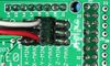
It is relatively simple to wire up the RAMPS. Just add the extruder heating coil wire to D10, the thermistor to the two pins on the bottom right, and wire up the steppers and endstops. From left to right, wire all of the stepper motor's wires as red, blue, green, and black into the pins next to the Pololus. When you connect the wires to the endstops (if you are using 3 endstops, plug them into the MIN slots), make sure you match the labes. The endstop pins and board pins are out of order, so make sure they match up. See the picture for full information.

Pre-Flight Check
If you think you may have mistakes you can install only one stepper driver during initial testing and risk only one stepper driver.
The trimpot on the stepper drivers controls the current limit. Turn it all the way down (counter clock wise) and back up 25%. Be careful to not force the trimpot, it is delicate. You will need to fine tune the current limit later. Note that it is allways giving the motors that much power, even when not moving, so if your stepper motor drivers are getting hot, you may want to turn it down slightly.
Connect the minimum endstops for X,Y, and Z
Connect Motors (Do not disconnect or connect motors while powered; if the connection is loose, this will cause the motors to spazz.)
Install firmware (More info below). Firmware flashing can be done without 12V power supply connected.
Warnings
The endstop pins are Signal - GND - VCC, instead of the VCC - Sig - GND like the rest of RepRaps boards. Make sure to wire them correctly. This is done to allow squeezing fatter traces on the printable board.
Connecting Power

There can be as many as three (3) power systems in place with a RepRap printer:
1) Arduino Power Supply: The barrel connector on the Arduino MEGA is not used in a RepRap printer. The Arduino, for what it needs to do, is perfectly happy being powered by the USB line power.
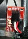
2) RAMPS Power Supply: The RAMPS shield has its own power supply, normally 12v @ 5A (minimum). Be careful connecting power to the RAMPS shield, for some reason the power connector is not obviously labeled. Looking at the power connector face on, the positive is on the left and the negative is aligned with the right edge of the card (see image).
3) Heated Bed Power Supply: Due to current considerations (trace thickness on the RAMPS) the Heated Bed may need to have its own power supply.
Power Supply
The RAMPS board requires 12v @ 5A or better.
The safest way to power a RAMPS board is to just supply it with 12 volts, which is an easy voltage to generate. This will avoid you frying things that shouldn't be fried by trying higher voltages than are really needed. Here are some options you can try:
- RAMPS is quite happy with the 12v line from PCPowerSupply.
- Another way to go is to hack a 12v laptop power supply
- Yet another way to go is to hack a 12v "wall wart" power supply.
- Yet another way is to hack an ATX computer power supply.
Maximum Input Voltage
The original flavor Arduino Mega (1280) is rated to a maximum 12v input. The newer Arduino Mega (2560) can take up to 20 V (but it is not recommended).
Power Supply without diode
The 1N4004 diode connects the RAMPS input voltage to the MEGA. If your board does not have this diode soldered in, you can safely input as much as 32 V. (The pololus can do up to 35V)
Power Supply with diode
If your board has a 1N4004 diode soldered in, do not apply more than 12 V to it.
Final Check

Note that tesla & tonok firmware use d9 and sprinter and johnny/tonok use d10 for the extruder hot end.
Version Specific Firmware and Pin Assignments
First, install and verify your Arduino IDE environment and Arduino board. If you are new to Arduino, get the 'blink' sketch working so you:
A) Know your way around the IDE in the most basic way
B) Have proven the Arduino board 100% functional
Here's the Arduino website: http://www.arduino.cc/en/Main/Software
Second, configure and upload the appropriate firmware for your RAMPS board into the Arduino:
RAMPS 1.4
RAMPS 1.4 info is being created at RAMPS 1.4
RAMPS 1.3
RAMPS 1.3 info is being created at RAMPS 1.3
RAMPS v1.2
Obtain, configure and upload one of the following RAMPS firmware into the Arduino:
https://github.com/kliment/Sprinter
- Try this one first
- (preferred)
https://github.com/kliment/Klimentkip
- Kliment's Tonokip-Firmware Fork with Acceleration, PID, SD support, and other goodies
- Updated frequently, with many active developers/hackers/users.
- (deprecated)
https://github.com/tonokip/Tonokip-Firmware
- Tesla893's Tonokip-Firmware fork, works w/ RepSnapper and Skeinforge
- Added Features over original Tonokip but not as up to date as Klimentkip
https://github.com/johnnyr/Tonokip-Firmware
- Works well with RepSnapper and Skeinforge
- Not as actively maintained
https://github.com/ramps/FiveD_for_RAMPS_GCode_Interpreter
- For use with Host Software or ReplicatorG
- Low level firmware that uses C instead of C++
Before you upload any of the above Firmware, be sure to confirm the following values in the
"Arduino Mega pin assignment" of their "pins.h" files:
// RAMPS v1.2
#define DEBUG_PIN           13

#define X_STEP_PIN (byte)   26
#define X_DIR_PIN (byte)    28
#define X_ENABLE_PIN (byte) 24
#define X_MIN_PIN (byte)     3
#define X_MAX_PIN (byte)     2

#define Y_STEP_PIN (byte)   38
#define Y_DIR_PIN (byte)    40
#define Y_ENABLE_PIN (byte) 36
#define Y_MIN_PIN (byte)    16
#define Y_MAX_PIN (byte)    17


#define Z_STEP_PIN (byte)   44
#define Z_DIR_PIN (byte)    46
#define Z_ENABLE_PIN (byte) 42
#define Z_MIN_PIN (byte)    18
#define Z_MAX_PIN (byte)    19

// Heated bed

#define BED_HEATER_PIN (byte)      8
#define BED_TEMPERATURE_PIN (byte) 1

// Extruder pins

#define EXTRUDER_0_STEP_PIN (byte)        32
#define EXTRUDER_0_DIR_PIN (byte)         34
#define EXTRUDER_0_ENABLE_PIN (byte)      30
#define EXTRUDER_0_HEATER_PIN (byte)      10
#define EXTRUDER_0_TEMPERATURE_PIN (byte) 2

#define EXTRUDER_1_STEP_PIN (byte)        23
#define EXTRUDER_1_DIR_PIN (byte)         25
#define EXTRUDER_1_ENABLE_PIN (byte)      27
#define EXTRUDER_1_HEATER_PIN (byte)       9
#define EXTRUDER_1_TEMPERATURE_PIN (byte)  8
My own implementation differed from what was given above, so I have implemented this in code:
// uncomment one of the following lines for RAMPS v1.3 or v1.0, comment both for v1.2 or 1.1
// #define RAMPS_V_1_3
// #define RAMPS_V_1_0

#ifdef RAMPS_V_1_3

#define X_STEP_PIN         54
#define X_DIR_PIN          55
#define X_ENABLE_PIN       38
#define X_MIN_PIN           3
#define X_MAX_PIN          -1   //2 //Max endstops default to disabled "-1", set to commented value to enable.

#define Y_STEP_PIN         60
#define Y_DIR_PIN          61
#define Y_ENABLE_PIN       56
#define Y_MIN_PIN          14
#define Y_MAX_PIN          -1   //15

#define Z_STEP_PIN         46
#define Z_DIR_PIN          48
#define Z_ENABLE_PIN       62
#define Z_MIN_PIN          18
#define Z_MAX_PIN          -1   //19

#define E_STEP_PIN         26
#define E_DIR_PIN          28
#define E_ENABLE_PIN       24

#define E_1_STEP_PIN         36
#define E_1_DIR_PIN          34
#define E_1_ENABLE_PIN       30

#define SDPOWER            -1
#define SDSS               53
#define LED_PIN            13
#define FAN_PIN            9
#define PS_ON_PIN          12
#define KILL_PIN           -1
#define ALARM_PIN          -1

#define HEATER_0_PIN       10
#define HEATER_1_PIN       8
#define TEMP_0_PIN         13   // ANALOG NUMBERING
#define TEMP_1_PIN         14   // ANALOG NUMBERING
#define TEMP_2_PIN         15   // ANALOG NUMBERING

#else

// The RAMPS_V_1_1 or RAMPS_V_1_2 board configuration has been chosen (default)

// The following section added to sychronize with RepRap Wiki entry
#define DEBUG_PIN          13

#define X_STEP_PIN         26
#define X_DIR_PIN          28
#define X_ENABLE_PIN       24
#define X_MIN_PIN           3
#define X_MAX_PIN           2   // For some reason this is noted as -1

#define Y_STEP_PIN         38
#define Y_DIR_PIN          40
#define Y_ENABLE_PIN       36
#define Y_MIN_PIN          16
#define Y_MAX_PIN          17   // For some reason this is noted as -1

#define Z_STEP_PIN         44
#define Z_DIR_PIN          46
#define Z_ENABLE_PIN       42
#define Z_MIN_PIN          18
#define Z_MAX_PIN          19   // For some reason this is noted as -1

#define E_STEP_PIN         32
#define E_DIR_PIN          34
#define E_ENABLE_PIN       30

// The following section added to sychronize with RepRap Wiki entry
#define EXTRUDER_0_STEP_PIN (byte)        32
#define EXTRUDER_0_DIR_PIN (byte)         34
#define EXTRUDER_0_ENABLE_PIN (byte)      30
#define EXTRUDER_0_HEATER_PIN (byte)      10
#define EXTRUDER_0_TEMPERATURE_PIN (byte) 2

#define EXTRUDER_1_STEP_PIN (byte)        23
#define EXTRUDER_1_DIR_PIN (byte)         25
#define EXTRUDER_1_ENABLE_PIN (byte)      27
#define EXTRUDER_1_HEATER_PIN (byte)       9
#define EXTRUDER_1_TEMPERATURE_PIN (byte)  8


#define SDPOWER            48
#define SDSS               53
#define LED_PIN            13
#define PS_ON_PIN          -1
#define KILL_PIN           -1
#define ALARM_PIN          -1


#ifdef RAMPS_V_1_0 // RAMPS_V_1_0
  #define HEATER_0_PIN     12    // RAMPS 1.0
  #define HEATER_1_PIN     -1    // RAMPS 1.0
  #define FAN_PIN          11    // RAMPS 1.0

#else // RAMPS_V_1_1 or RAMPS_V_1_2
  #define HEATER_0_PIN     10    // RAMPS 1.1
  #define HEATER_1_PIN      8    // RAMPS 1.1
  #define FAN_PIN           9    // RAMPS 1.1
#endif

#define TEMP_0_PIN          2    // MUST USE ANALOG INPUT NUMBERING NOT DIGITAL OUTPUT NUMBERING!!!!!!!!!
#define TEMP_1_PIN          1    // MUST USE ANALOG INPUT NUMBERING NOT DIGITAL OUTPUT NUMBERING!!!!!!!!!
#endif
1) Open the Arduino IDE
2) Navigate to the directory where the Sprinter source code is located.
3) Double click on Sprinter.pde
4) Compile.
You should see the following in your status window "Binary sketch size: 52,760 bytes (of a 258,048 byte maximum)"
(if you are using an Arduino Mega 2560).
5) Upload the compiled code to your RAMPS board
RAMPS v1.1
Confirm these values in the "Arduino Mega pin assignment" of the "pins.h" file:
// RAMPS v1.1c
#define DEBUG_PIN        13

#define X_STEP_PIN (byte)26
#define X_DIR_PIN (byte)28
#define X_MIN_PIN (byte)3
#define X_MAX_PIN (byte)2
#define X_ENABLE_PIN (byte)24

#define Y_STEP_PIN (byte)38
#define Y_DIR_PIN (byte)40
#define Y_MIN_PIN (byte)16
#define Y_MAX_PIN (byte)17
#define Y_ENABLE_PIN (byte)36

#define Z_STEP_PIN (byte)44
#define Z_DIR_PIN (byte)46
#define Z_MIN_PIN (byte)18
#define Z_MAX_PIN (byte)19
#define Z_ENABLE_PIN (byte)42

// Heated bed

#define BED_HEATER_PIN (byte)8
#define BED_TEMPERATURE_PIN (byte) 1


//extruder pins

#define EXTRUDER_0_STEP_PIN (byte)32
#define EXTRUDER_0_DIR_PIN (byte)34
#define EXTRUDER_0_ENABLE_PIN (byte)30
#define EXTRUDER_0_HEATER_PIN (byte)10
#define EXTRUDER_0_TEMPERATURE_PIN (byte)2

#define EXTRUDER_1_STEP_PIN (byte)23
#define EXTRUDER_1_DIR_PIN (byte)25
#define EXTRUDER_1_ENABLE_PIN (byte)27
#define EXTRUDER_1_HEATER_PIN (byte)9
#define EXTRUDER_1_TEMPERATURE_PIN (byte)8
RAMPS v1.0
This is the original PCB that was available from Ultimachine in Sept 2010.
This board can be used with FiveD without modifications with the above pin definitions. The extruder heater ouptuts will be on the screw terminals marked D10. You can cut the traces on top of the board and wire pins 8 and 9 to the other 2 mosfets if needed for heated bed, etc. Pins 11 and 12 can not currently be used with the FiveD firmware due to a conflict with the interupt timer . The following pin definitions can be used with Tonokip_Firmware(Note baud rate defaults to 115200 in this firmware) controlled by RepSnapper Manual:Introduction software.
// RAMPS v1.0
#define X_STEP_PIN         26
#define X_DIR_PIN          28
#define X_ENABLE_PIN       24
#define X_MIN_PIN           3
#define X_MAX_PIN           2

#define Y_STEP_PIN         38
#define Y_DIR_PIN          40
#define Y_ENABLE_PIN       36
#define Y_MIN_PIN          16
#define Y_MAX_PIN          17

#define Z_STEP_PIN         44
#define Z_DIR_PIN          46
#define Z_ENABLE_PIN       42
#define Z_MIN_PIN          18
#define Z_MAX_PIN          19

#define E_STEP_PIN         32
#define E_DIR_PIN          34
#define E_ENABLE_PIN       30

#define LED_PIN            13
#define FAN_PIN            -1
#define PS_ON_PIN          -1
#define KILL_PIN           -1

#define HEATER_0_PIN        12
#define TEMP_0_PIN          2   // MUST USE ANALOG INPUT NUMBERING NOT DIGITAL OUTPUT NUMBERING!!!!!!!!!
Schematic

Bill of Materials
| ID | Description | Quantity | Part Number | Reichelt Order Number |
|---|---|---|---|---|
| U1 | Arduino Mega | 1 | 2560 or 1280 | |
| U2,U3,U4,U5 | Pololu stepper driver boards | 4 | ||
| C4 | 100nF capacitor | 1 | X7R-2,5 100N (verified) | |
| C5,C8 | 10uF capacitor | 2 | RAD 10/35 (verified) | |
| C6 | 100uF capacitor | 1 | RAD 100/25 (verified) | |
| R1,R7 | 4.7K resistor | 2 | METALL 4.70K | |
| R2,R3,R4,R5,R6,R8,R9 | 100K resistor | 7 | 1/4W 100K | |
| Q1,Q2,Q3 | N-channel Protected Mosfet | 3 | STP55NF06L | ZXM 64N035 L3 |
| D1 | Diode | 1 | 1N4004 | 1N 4004 |
| F1 | PTC resettable fuse (30V, Hold5A, Trip10A) | 1 | MF-R500 | PFRA 500 |
| J2 | 5.08 Eurostyle screw terminal | 1 | 282837-6 | AKL 101-06 |
| LED1 | 3mm Green LED | 1 | LED 3MM ST GN | |
| S1 | Push button switch | 1 | FSMRACD | TASTER 3305B |
| X1 | Power jack (Plug and fixed receptacle) | 1 | MSTBA 2,5 and MSTBT 2,5 (5.04mm spacing 2 connector) | AKL 249-02 AND (AKL 230-02 OR AKL 220-02) |
| 2 x 12 pin header | 2 | |||
| 2 x 9 pin header | 1 | |||
| 20 pin header | 1 | SL 1X36G 2,54 (3 of these) | ||
| 2 x 18 Pin Stackable Female Header (non stackables can be used with plated through holes) | 1 | MALE: SL 2X25G 2,54 (2 of them, shortened with a saw or pliers) | ||
| 8 Pin Stackable Female Header (non stackables can be used with plated through holes) | 5 | |||
| 6 Pin Stackable Female Header (non stackables can be used with plated through holes) | 1 | |||
| 16 Pin Female Header | 4 | BL 1X20G8 2,54 (shortened with a saw or pliers) | ||
| 0.1" Jumpers | 12 | |||
| Circuit Board | 1 | v1.2 (instructions for other versions available in the history at the top of this page. |
A shopping cart for the german distributor reichelt has been assembled (by lImbus). All components listed above are available for 8.78 Eu (shipping excl)
If you etch your own board, you will need to make sure to get the stackable headers to connect to the Arduino MEGA. You can use cheaper, non stacking headers if you have a normal commercial double sided board with plated holes.
Point to point wiring when using a proto shield


It is possible to make this circuit with a proto shield by running wires directly between the pins. Make sure to check the prototype shield you use for pin holes that have traces tying them together. You most likely will have to cut some traces to keep from shorting circuits together. The board used here is the Arduino Mega shield one manufactured by Arduino. I only had to cut traces in about 4 places and it only took a couple seconds each with the little grinding bit on a dremel tool. Pictured below are the traces that need cut on the Tinker-It shield, both traces need cut in the small red circle, the top trace cut twice in the big circle to isolate the pins there.
If wiring a shield make sure to leave the area above the usb jack and ISCP header clear of components or the board is spaced / electrically insulated sufficiently to avoid shorts to the Arduino Mega board components.
Heated Bed
The reason why people install a heated bed is to improve the chances of a good print.
All of the methods involve moving a significant amount of current through a heat release mechanism, controlled by a thermistor. A little bit like the way an automatic kettle works - it heats until the desired temperature is achieved, then it stops heating.
This means that at least FOUR connections need to be made
- The heating element(s) of the bed need both POSITIVE and NEGATIVE leads to be connected
- The Thermistor needs to be securely adhered to the bed (Kaptonized) - The thermistor element needs its leads to be connected to the RAMPS board - The RAMPS connector for the Thermistor is T1
using a relay and a separate PSU
get a 12V relay, wire the switching circuit in any direction to the ramps and connect the switched circuit to the second PSU and bed
powering the heated bed through the RAMPS
Warning: The power input connector on RAMPS is not rated for the current needed to run a heated bed. Do not attempt this if you are afraid that your MOSFET will release magic smoke. This has not been tested on V1.0, and might not work as well due to its thinner MOSFET traces.
It is possible to run your heated bed off the RAMPS shield without a relay. BUT always be sure not to short any of the D connections while powered, this will will destroy the mosfet.
Check to see if your firmware supports a heated bed (tonokip does) and get the pin settings right.
repsnapper is showing you the bed temperature too.
powering the heated bed directly from a separate PSU, grounding on the RAMPS
get your scope and check if you have potential differences on the PSUs. connect the additive PSU on the hot side to the bed, connect the bed ground to - on the RAMPS (D8) check if you have current flow between the different grounds of the PSU. cause the mosfet is just switching the bed on and off it is barely getting hot and can handle the power pretty well. if so, it should not be possible to heat up the bed this way
powering the heated bed directly form the main PSU, grounding on the RAMPS
connect + from the PSU to the power plug of the RAMPS; connect the bed directly to the main power +, connect the other side of the bed (ground) to - on the RAMPS (D8) cause the mosfet is just switching the bed on and off it is barely getting hot and can handle the power pretty well.
Electronics Enclosure
Modular Enclosure
The previous enclosure isn't printable on a Makerbot. This one is Modular RAMPS Case on Thingiverse
The openscad script is available so you can modify the files if you want.
OG Enclosure
This is an enclosure for the RAMPS version 1.2 it will not work with other versions. Feel free to join the race to get an awesome case for v1.3
It has a mount built in for a 40mm fan and LED. Shown printed in PLA. There is talk that it is currently unprintable in ABS due to warping.
It uses 2.8mm holes to for the 3x16mm cap screws that mount it and the Arduino stack inside. These holes print a little undersized with my configurations and hold a 3mm screw pretty good.
The files say v1.1, but the enclosure is also compatible with v1.2
| IMAGE | FILE ID# | TYPE | DESCRIPTION | DOWNLOAD |
|---|---|---|---|---|

|
File:RAMPS1-1case.zip | STL | All the stl files for the v1.1 enclosure in a zip | media:RAMPS1-1case.zip |

|
File:RAMPS ADfiles.zip | Alibre Design Files | These are the original design files. | media:RAMPS ADfiles.zip |

|
RAMPS-Case-Top3 | STL | The lid for the enclosure. Has mount for 40mm fan. Chose the one that fits your vs of the board with or without UltiMachine logo. | media:RAMPS-Case-Top3v1-1.stl
media:RAMPS-Case-Top3v1-1noUlogo.stl media:RAMPS-Case-Top3v1-0.stl |

|
RAMPS-Case-Base3 | STL | The bottom half of the enclosure. Chose the one matching your vs. | media:RAMPS-Case-Base3v1-1.stl |

|
File:RampsWindow.stl | STL | Covers teardrop holes and serves as reset button lever | media:RampsWindow.stl |

|
File:RampsResetButton.stl | STL | Attached through window with 3mm filament. | media:RampsResetButton.stl |

|
File:RampsMountSpacer.stl | STL | Spacer to raise enclosure up above the bottom nut outside the frame vertex. | media:RampsMountSpacer.stl |