Rambo
Release status: Working

| Description | An all in one RAMPS class motherboard targeting convenience, reliability, and performance
|
| License | Creative Commons Attribution-ShareAlike 3.0
|
| Author | |
| Contributors | |
| Based-on | |
| Categories | |
| CAD Models | |
| External Link |
Contents
Summary
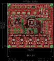
RAMBo (RepRap Arduino-compatible Mother Board) is an all in one RAMPS class motherboard targeting convenience, reliability, and performance.
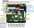
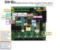
All connectors
Main connectors
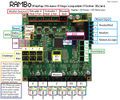
Auxiliary connectors
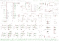
Schematic
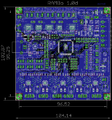
Top/1stv1.0 copper layer
Ground/2ndv1.0 copper layer
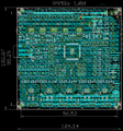
Supply/3rdv1.0 copper layer
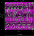
Bottom/4thv1.0 copper layer


Features
Logic
- Arduino MEGA compatible Atmega2560 and Atmega32u2 processors are compatible with all RAMPS class firmwares
- Crystals for both usb and mcu (timing accurate to 10ppm)
- 4 Thermistor jacks
- All extra pins broken out on both processors (allows using the 32u2 for LUFA AVR programmer, etc.)
- 2 channel SDRAMPS compatible SPI breakout
Motor Drivers
- 5 A4982 1/16th microstep motor drivers (A4984 1/8th prior to v1.1) (2 connectors on Z for Prusa Mendel and other dual Z printer designs)
- Digital Trimpot for stepper current control
- Current limit on driver IC VCC to prevent permanent latchup
- Microstep mode configured by MCU through firmware (no jumpers needed)
- Test points for driver control signals
- Step and Direction pins are on their own ports for synchronous movement capability
- Extra driver ports broke out for up to 3 additional drivers (some of the motor extension pins are shared with max endstop and a pin allocated for SPI-SS extensions)
PWM DC outputs (Extruders, Fans, Etc.)
- 6 outputs
- Low resistance mosfets for cool running
- Indicator led for each channel
Power
- Three independent power rails
- Heated Bed 15A, < 32V recommended max 24V (version earlier than 1.1 limted to 14A 16V due to fuse rating, see rambo_development for hacks)
- Extruders 5A (fuse can be exchanged for up to 10A capacity) 10V-26V input voltage
- Motors and logic 5A (fuse can be exchanged for up to 10A capacity) 10V-26V input voltage
- Built in SMPS for 5V generation from 10V-26V Vin
PCB
- 4 layer
- 2oz copper on all layers
- High quality, High temperature FR4-TG130 PCB
- Gold ENIG finishing
LCD panel support
There is now a fairly easy to do method for using a reprapdiscount LCD smart controller with a RAMBo. See RamboLCD for instructions
Firmware
Support for RAMBo is in Marlin
USB Driver
Windows requires a driver to communicate with RAMBo. In windows 7, plug in your RAMBo board, and let windows fail to find the driver. Then, go to the start menu, right click on computer and click properties. On the left, click on Device Manager. Scroll down to Unknown Devices, and right click on RAMBo. Choose Update driver. CLick on "Browse my computer for driver software", then click on "Let me pick from a list of device drivers on my computer", then click the button for "Have Disk" and then click browse and point it to the file you downloaded above.
Linux and Mac use the built in CDC driver. RAMBo should show as a option in your 3D printer control interface (/dev/ttyACM0 , etc.).
Motor Current
The current for the stepper motors is set by firmware controlling the 8-bit digital potentiometer. The following formula from the Allegro datasheet describes how to set the reference voltage: ITripMAX = VREF/(8 X RS). RS, the value of the sense resistor on RAMBo is equal to 0.1<math>\Omega</math>. ITripMAX is the current the stepper motors are rated for. Ideally you should start with 70%-90% of maximum. You can verify the voltage for each driver by plugging the reference voltage (VREF) measured at the X_REF test point (Y_REF,etc for the other drivers) in the following formula:
<math> V_{Ref}= I_{TripMAX} \times 0.8</math>
Note the A4982 is set to be limited to 2A. This means the adjustable voltage range is 0 to 1.66 volts. The following formula will yield the 8-bit binary value, <math>W_v</math>, to be entered into firmware or directly over SPI.
<math>W_v = \frac{V_{Ref}}{1.66} \times 255</math>
Schematic

Devolopment information
There is a page at Rambo_development with the pin assignments, fuses, changelog, etc.
Credits
Board designed by johnnyr. Based on work, research, and documentation published by open source heroes: Arduino, RepRap, Adrian Bowyer, Nophead, Zach Smith, Vik Oliver, Tonokip, Josef Prusa, Kliment Yanev, Jordan Miller, Joachim Glauche, and many many more Reprappers, etc.