Re-ARM
|
English • العربية • български • català • čeština • Deutsch • Ελληνικά • español • فارسی • français • hrvatski • magyar • italiano • română • 日本語 • 한국어 • lietuvių • Nederlands • norsk • polski • português • русский • Türkçe • українська • 中文(中国大陆) • 中文(台灣) • עברית • azərbaycanca • |
Release status: Working
[[image:|center|190px]]
| Description | LPC1768 for use with RAMPS 1.4
|
| License | |
| Author | |
| Contributors | |
| Based-on | |
| Categories | |
| CAD Models | |
| External Link |
Contents
Summary
UNDER CONSTRUCTION
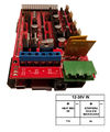
Re-ARM is a R3 form factor NXP LPC1768 based controller. It is meant to replace an Arduino mega260.
Software
Smoothieware - see xxxx for a useable configuration
Marlin - under construction - will be supported in Marlin 2.0
Compatible Shields
RAMPS1.4 is the only known compatible shield.
RAMPS-FD has a mechanical interference problem.
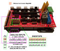
Pinout when used with RAMPS1.4
The LPC1768 has fewer I/O pins than the mega2560 which results in some logical pins no longer available and some logical pins being available on two different pins.
The logical pin numbers in the gallery are Marlin.
/**
*  The following pins are NOT available in a Re-ARM system
*  7
*  17
*  22
*  23
*  25
*  27
*  29
*  32
*  39
*  40
*  42
*  43
*  44
*  45
*  47
*  64
*  65
*  66
*/
/**
 * special pins
 *   D37 - not 5V tolerant
 *   D49 - not 5V tolerant
 *   D57 - open collector
 *   D58 - open collector
 *
 */
*  PWMS
*
*  There are 6 PWMS. They do NOT share resources with the system so all 6 are available.
*
*  SERVO2 does NOT have a PWM assigned to it.
*
Analog inputs - there are 8 analog inputs on the Re-ARM compared with 16 on the mega2560.
- A0 (T0) - D67 - TEMP_0_PIN
- A1 (T1) - D68 - TEMP_BED_PIN
- A2 (T2) - D69 - TEMP_1_PIN
- A3 - D63
- A4 - D37 - BUZZER_PIN
- A5 - D49 - SD_DETECT_PIN
- A6 - D0 - RXD0
- A7 - D1 - TXD0
D63, D67, D68 & D69 still have analog inputs assigned to them.
D67, D68 & D69 are the only analog inputs that don't require external signal conditioning. All the others have huge (25% & more) spikes.
D67, D68 & D69 are available on the RAMPS board or on the Re-ARM board. The ones on the Re-ARM board have less noise on them. Solder jumpers J7, J9 & J10 select which pins are active. The board comes with the RAMPS pins enabled.
When configured as an analog input, the pins are NOT 5V tolerant. The useable range is 0 - 3.3V.
LCDs
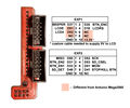
Most LCDs are expected to use the J3 & J5 connectors on the Re-ARM board. J3 is pinned out for the 12 pin Viki2 LCD flat ribbon cable.
The standard SMART LCD adapter can be used to interface RepRap Discount Full Graphic type of controllers. The pinout is different than when used with a mega2560.
- If your LCD requires +5V then you'll need a special EXP1 cable.
- If your LCD uses any of the following signals then you must use J3 & J5:
- - LCD_PINS_D5, LCD_PINS_D6 & LCD_PINS_D7
- - DOGLCD_A0 & DOGLCD_CS
NOTE - The mega2560 pinout used two SPI channels but the Re-ARM only routes one to this adapter. The result is garbage/lines appearing on the RepRap Discount Full Graphic display when the SD card is accessed. Sometimes the garbage/lines remains on the "Print from SD card" submenu screen after the SD card accesses are finished.


