VerticalPlatform
Contents
The RepRap Vertical Axis
-- Main.VikOlliver - 27 Nov 2005
Version 1 *DRAFT*
1. Summary
This describes how to construct the vertical axis of a prototype RepRap from FDM'd parts. As with other RepRap components, this axis and platform was designed to be made by the RepRap rapid prototyper itself, and thus consists of standard parts plus rapid-prototyped components. Very few modifications are required to the standard components.
The platform is designed to be raised and lowered to an accuracy of better than 0.1mm by means of a stepper motor and threaded rods. The whole is designed to be mounted on a carriage on the linear axis, and to transport either a second linear axis or a turntable assembly.
2. Introduction
The axis is derrived from an experimental Meccano axis, used to produce parts from EVA during the early stages of RepRap development. This prototype worked, but was prone to uneven descent of the platform as it used only one screw to raise and lower it. Although 3 guide rails were used, these had a tendency to bind at awkward moments, resulting in a see-saw motion during descent.
The platform is mostly used after a period of descent, and the margin of error is relatively large compared with the amount of each unit of descent. Also, as forces on the nuts always act in the same direction, no anti-backlash system is needed. In short, we don't have to be too precise as long as we remain level.
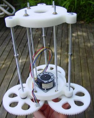
- The vertical axis main component assembled from FDM'd parts
The first FDM'd prototype uses 3 pieces of M5 studding to control the descent of the platform, which adds to the stability. These pieces of studding are turned by 3 large gears, which in turn are driven by a stepper motor (see this section for intricate design details]. The gearing provides approximately 5:1 reduction of a 7.5 degree stepper motor, rotating the studding in 1.5 degree steps. The thread pitch on M5 studding from this table http://www.hydra.co.za/technical/thread.pdf is 0.8mm, resulting in a theoretical 30 steps to move the platform by 0.1mm vertically. This accuracy overkill is needed because of the gearing ratio required to allow the stepper motor's torque to lift the platform assembly under load.
Identical end pieces are used at the top and bottom of the lengths of studding, which as well as holding bearings for the studding form anchor points for the stepper motor and equipment attached to the top of the platform.
Provision has been made for additional stiffening should it be required. The four holes in a square around the central axis of the platform are for lengths of M4 studding, which are used to align and stiffen the body of the axis.
The M5 studding runs freely through captive nuts mounted on the carriage of a linear axis, causing the whole platform assembly to raise and lower when the stepper motor turns. In effect, the whole mechanism hangs from these three nuts.
3. Assembly
Start by cutting the M4 studding (F) into 4 x 200mm lengths. Bevel the ends with a file to ensure an M4 nut will fit on. Place a nut on one end of each length of M4 studding, and screw it on 10mm. Slip an M4 washer on the short end of each length of studding. Insert the short end of the studding through the concave side of each of the 4 holes in the square arrangement on one of the spiders (A). Add another M4 washer onto each length of studding, and secure all 4 lengths of studding. There should be no more than 1mm of studding standing proud of each nut. This is the bottom end of the construction. Put the assembly to one side.
Cut 3 x 200mm lengths of M5 studding (E) and bevel the ends so nuts fit on. Ensure lengths are absolutely dead straight (eyeball from one end or use a known flat surface). Screw an M5 nut onto each length of M5 studding, screwing it down to approx. 15mm from the end.
Take one of these lengths, and put an M5 washer on the short end of the thread. Place the flat side of a large gear (B) against the washer, and screw an M5 nylock nut on afterwards, so that the built-in plastic sleeve is just past the beveled end of the thread. Tighten the plain M5 nut so that the gear is secured to the M5 studding, the body of the nylock nut going into the nut-shaped recess on the large gear. Repeat for the other two lengths of M5 studding.
Take a 15mm length of 2mm PVC tubing (G) and slip it over the shaft of the stepper motor (M). If it is not a tight fit, add a little Loctite adhesive or first wrap the spindle with a little PTFE tape - but try to keep the tape even or the motor will be offset. A bad thing.
Firmly push the covered shaft into the hole in the centre of the pinion gear (C), trying to keep the gear as square on to the motor shaft as possible. You will probably not manage to get all of the shaft into the gear. Ensure the motor and gear rotate smoothly and evenly.
Insert the pinion gear into the large hole in the centre of the bottom spider from the top surface. Secure the stepper motor to the spider with 2 x ??mm M3 cap screws, 4 washers and 2 nuts. Insert the screws from the bottom so that they do not protrude into the gearing mechanism.
Put one normal M5 washer and one 12mm-wide M5 washer onto each gear-equipped length of studding. Poke one of these gear assemblies into each of the three M5 holes in the bottom spider.
Take this assembly and push all the lengths of studding through the corresponding holes in the carriage on your linear axis. It will only go on properly one way. Screw an M5 nut onto each of the three protruding ends of the M5 studding about 100mm. Place the nut holders from the linear axis on top of the M5 nuts - it is not necessary to secure them at this point.
Onto the protruding end of each of the four lengths of M4 studding, screw a nut down about 15mm, and add an M4 washer on top of each nut. This is where the top spider will sit, concave end facing the other spider. Try the fit of the top spider and adjust the 4 M4 nuts until the distance between the two spiders is equal all the way around. Slip an M4 washer and nut on top of each of the protruding M4 rods, and tighten.
Slip an M5 washer over each of the three protruding M5 rods, and cap each rod off with a nylock nut. This nut should be nowhere near tight and leave considerable play in the M5 rod assembly. Their only purpose is to stop the whole assembly falling appart when ypu fiddle with it - they do not stabilise the structure in any way while it is in operation.
The M5 nuts above the carriage can now be adjusted to level the Vertical Platform, and the nut holders can then be secured. Lightly grease the gears with Vaseline or similar. The Vertical Platform is then ready to receive the stage.
4. Electronics
TBA
5. Components
Mechanics (Under development)
| Number off/quantity | Description | Supplier |
| 2 | Spiders (A) | RP part |
| 3 | Large gears, 79 tooth (B) | RP part |
| 1 | Pinion gear, 16 tooth (C) | RP part |
| 1m | steel M5 studding (E) | RS (530-315), Farnell (517343) |
| 1m | steel M4 studding (F) | Hardware store |
| 15mm | 2mm ID PVC tubing (G) | Garden shops & hydroponic centres |
| 1 | Unipolar 12V 7.5 deg stepper motor 49.5mm centres (M) | Mitsumi M42SP-5 |
| 8 | steel or brass M4 nuts | RS (525-896), Farnell (149682) |
| 2 | steel or brass M3 nuts | RS (837-206), Farnell (758796) |
| 2 | steel or brass M3 washers | RS (560-338), Farnell (149687) |
| 2 | steel 25 mm M3 cap screw | RS (376-4555), Farnell (100165) |
| 1? | steel 30 mm M4 cap screw | RS (376-4656), Farnell (8840482) |
| 2? | steel or brass M4 washers | RS (525-925), Farnell (149689) |
| 6 | M5 Nylock nuts | Hardware store |
| 3 | Steel or brass M5 nuts | Hardware store |
| 3 | steel M5 Washers | Hardware store |
| 3 | steel 12mm OD M5 "fender" washers | Hardware store |
Electronics
TBA
Licence
RepRap is copyright 2005 University of Bath, the RepRap researchers (see the project's People page), and other contributors.
This web page and all the other files in its download are covered by that copyright.
Principal author:
Adrian Bowyer Department of Mechanical Engineering Faculty of Engineering and Design University of Bath Bath BA2 7AY U.K. e-mail: [email protected]
RepRap is free; you can redistribute it and/or modify it under the terms of the GNU Library General Public Licence as published by the Free Software Foundation; either version 2 of the Licence, or (at your option) any later version.
RepRap is distributed in the hope that it will be useful, but WITHOUT ANY WARRANTY; without even the implied warranty of MERCHANTABILITY or FITNESS FOR A PARTICULAR PURPOSE. See the GNU Library General Public Licence for more details.
For this purpose the words "software" and "library" in the GNU Library General Public Licence are taken to mean any and all computer programs computer files data results documents and other copyright information available from the RepRap project.
You should have received a copy of the GNU Library General Public Licence along with RepRap; if not, write to the Free Software Foundation, Inc., 675 Mass Ave, Cambridge, MA 02139, USA, or see
http://www.gnu.org/
-- Main.VikOlliver - 25 Nov 2005
NOTE: Please see the SVN repository on Sourceforge for definitive versions of these files.
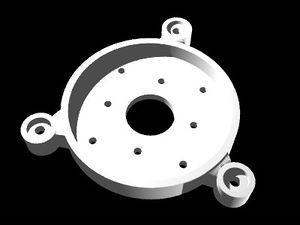
- [[File:VerticalPlatform-lower spider2.aoi: Second version of the spider used to hold the vertical axis gears|thumb]]
- AoI Rendering of the spider designed to hold the gears:
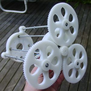
- [[turntable_vertical_cogs.aoi: AoI file of gears used in vertical platform.|thumb]]
- Vertical axis showing gear end:
- [[File:VerticalPlatform-spider 2 of.stl: Slotted version of spider. Make 2.|thumb]]


