ArcCompensation
Arc Compensation
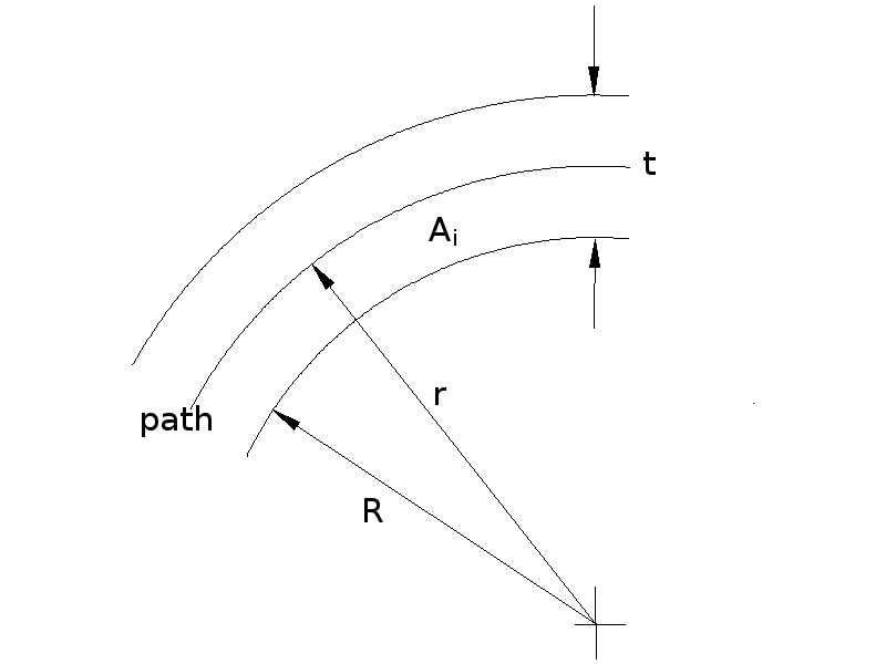
Reprapper Nophead has pointed out that when the RepRap extrude head moves it lays down material equally on either side of its centre line. But when an arc is being created, less material is needed on the inside of the arc than the outside. This page describes the calculation that's needed to compensate for that.
Suppose RepRap is making a circular hole of radius R. The extrude head lays down a track of thickness t. The head has to move at an offset radius r to get the edge of the hole in the right place. For big values of R:
r ≈ R + 0.5t.
Indeed for straight lines (i.e. when R is infinite), that is exactly what you want. But for small R the hole will come out too small because more material is laid down in the inside area, Ai than is needed. So r has to be larger than the simple calculation gives to compensate.
Without loss of generality, consider the entire circle of which the arc along which the centre of the extruder moves is a part. Let the circumference of the circle be length L:
L = 2πr
Clearly, for a straight line (that is, infinite R):
Ai = Lt/2 = 2πrt/2 = πrt
For finite values of R:
Ai = π(r2 - R2)
If we equate the Ai values so that r gives the inner area we would have for a straight line we have
πrt = π(r2 - R2)
The πs cancel, giving (after re-arrangement) the quadratic in r:
r2 - rt - R2 = 0
which has the root:
r = [t + √(t2 + 4R2)]/2
(There is also the negative square root which we can ignore.) We can tabulate this formula for some typical values. For t = 0.5 mm, say:
| R (mm) | r (mm) |
| 1 | 1.28 |
| 1.5 | 1.77 |
| 2 | 2.27 |
| 2.5 | 2.76 |
| 3 | 3.26 |
| 3.5 | 3.76 |
| 4 | 4.26 |
| 4.5 | 4.76 |
| 5 | 5.26 |
| 5.5 | 5.76 |
| 6 | 6.26 |
| 6.5 | 6.75 |
| 7 | 7.25 |
| 7.5 | 7.75 |
| 8 | 8.25 |
| 8.5 | 8.75 |
| 9 | 9.25 |
| 9.5 | 9.75 |
| 10 | 10.25 |
As you can see, above R = 6.5 mm, the simple offset calculation of adding half t gives the right answer to within 10 microns. But below that the differences are significant.
The RepRap Java code implements the correction needed using two extruder parameters: Extruder0_ArcShortSides(0..) and Extruder0_ArcCompensationFactor(0..) (and similarly for other extruder numbers than 0). The correction described above is multiplied by Extruder0_ArcCompensationFactor(0..). Thus setting this to 0 (the default) means that no compensation is done. Setting it to 1 gives exactly the algebra above. But most extrudates are highly non-Newtonian; this seems to mean that one needs to set the factor much bigger than 1. To get the right effect for ABS I use 8, for example.
STL files know nothing about circles, of course; everything is faceted. The way the code works is to go round each polygon that results from a slice through the STL triangles examining each point and its immediate neighbours. If the two line segments to the neighbours are both shorter than Extruder0_AngleSpeedLength(mm) then a circle is fitted through the three points and the correction applied to the central one. This prevents the code from doing anything with points that, for example, form a right-angled corner in an object with two long sides. I set Extruder0_ArcShortSides(0..) to 2. That seems to pick up genuine arcs, curves and circles (which are made from lots of short segments, of course) while leaving gross features alone.
-- Main.AdrianBowyer - 26 Jul 2008
Open questions
Several popular alternatives to G-code use cubic splines. Do we need some sort of compensation similar to "arc compensation" when such splines have tight curves? If so, how do we calculate how much compensation to use?
Is a "Savitzky–Golay smoothing filter" the right approach?
