Delta Rostock mini G2s Build Manual
Building Instruction
For detailed building instruction, please visit here.
You can also download the PDF version here Media:Delta Rostock mini G2& G2s building instruction.pdf
Check Your Kit
Make sure to check the shipping manifest before you begin your build - if any part is missing (or duplicated), immediately contact Geeetech support.
If you can, take a picture of the complete kit - all laid out - and a picture of the shipping manifest with the 'Signed off by' signature in the photo. This will help Geeetech quickly verify the missing components, and start the RMA process.
Additional Tools
Some additional tools that you might find useful:
Assembly Tools
- Metric Hex key set from 1mm to 4mm
- Digital calipers
- Metal metric ruler (to measure distances too long for the calipers, and to determine bed flatness)
- Wire strippers
- Soldering iron (to make the heatbed 2-3 bridge if needed)
Printing Tools
- Wire cutters (useful for snipping plastic)
- Masking or Blue tape (for PLA printing)
Assembly Tips
These assembly tips are community provided, and are not official Geeetech recommendations.
Use at your own risk. If in doubt, contact Geeetech directly for supported assembly assistance.
General Tips
- Verify that all parts in the shipping manifest are present before you begin.
- Read the entire build manual before you begin!
- There are photos later in the manual that may help you with earlier build steps.
- Use a white plate or piece of paper to hold all the small pieces you need for a build step.
- This way you can make sure you have all the pieces at the ready, and missed none.
- If you have to use more than a light pressure to complete a step - check the assembly tips below!
- Very rarely is more than a light pressure needed to complete this kit. Too much force can break the acrylic or printed parts.
Acrylic Fasteners
It it very easy to break the acrylic by over tightening teh M3 square nuts.
If the acrylic piece does not fully seat into its socket, lightly sand the socket and the corners of the piece until they fit correctly (a light pressure should fully, but firmly, seat the piece into the socket).
The Acrylic 'square' M3 nuts are designed for a light load. When tightening the bolt into the nut, only tighten to a snug fit.
DO NOT OVERTIGHTEN THE BOLT INTO THE SQUARE NUT!
Driving Pulley Attachment
When attaching the driving pulley to the stepper motor, the shaft of the stepper motor should extend approx 4mm from the face of the pulley.
After tightening the primary screw against the flat of the motor shaft, either remove or fully tighten the remaining screw in the pulley.
Failure to do so will allow the screw to wiggle loose during printing, and will case the pulley to jam against its acrylic enclosure.
Initial Bed Levelling (during build)
During bed installation, use a reference height (such as a M3x12 bolt from bag 18) to make sure that each top of each bed mounting point is the same after tightening the wingnuts.
Simply place a M3x12 bolt (head down) next to the bed (not under!), and tighten until the end of the bolt it at the same level as the top of the bed. Repeat for the other two mounts.
Z-Probe Switch and Rod-End Bearing Installation Order
The G2/G2S Build Manual (as of Sept 4, 2015) has the Z-Probe Switch installation procedure before the Rod-End Bearings procedure.
If done in that order, the Z-Probe Switch will prevent the installation and tightening of the Rod-End Bearing retaining bolts.
Reorder the building instructions as follows:
- Proceed through the manual until you reach the Z-Probe and Switch installation section.
- Skip ahead, and install the Spider's Rod-End Bearings (but not the Diagonal Rods themselves)
- Return to the Z-Probe and Switch installation chapter.
- Continue instructions as per normal from the point after the Z-Probe Switch installation
Z-Probe Switch Installation
For the Z-Probe switch, you are required to screw through both the switch and the spider with the M3 retaining bolt.
Before installing on the spider, screw both bolts through the switch until the ends are flush with the opposite side of the switch.
When installing on the spider, tighten each bolt a 1/4 turn at a time, until both bolts have begun to screw into the spider, then tighten normally.
There should be no more than a 1mm gap between the Z-Probe Switch and the spider.
Alternatively, widen the switch's mounting holes using a 1/8" US drill bit.
Smooth Rod Tightening
Always finger-tighten first - you should only need 1/4 to 1/2 of a turn of your hex wrench to fully tighten the 4mm bolts into the smooth rods.
It can be difficult to tighten the lubricated smooth rods by hand. If you have a pair of vice-grips, you can pad the jaws (foam or cloth to prevent scratches to the smooth rods) and clamp down tightly.
If you cannot finger-tighten the 4mm bolts fully, add washers! - see the Assembly Mods section below for details. Since the 4mm threads in the smooth rods are 'blind' (they don't have an exit hole for debris) if they have a metal chip or other debris inside, the 4mm bolt won't fully seat. Attempting to over-tighten the bolt in the blind threaded hole may break your hex wrench, or the head of the bolt itself!

Vice-grips padded with foam to prevent scratches.

Idler Pulley
Tighten the retaining bolt
It is of critical importance to fully tighten the bolt in the middle of the sheet metal U holder for the idler pulley.
If the bolt is not fully tightened, when the wingnut is used to secure the pulley, it can cause the bolt to back out slightly, and press against the belt. This can then cause the belt to jam, and cause a head crash.
Tighten the wingnut
The wingnut cannot be used to adjust belt tension (unless you use the 'Idler Pulley Guide' modification). The wingnut must be fully tightened, or the sheet metal holder can 'lean' slightly, and cause the belt to jam against the pulley holder.
Adjust belt tension by loosening the wingnut, changing the belt notch that is held by the carriage belt retainer, then fully tightening the wingnut.
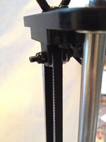
Note the canted idler pulley, and the belt jammed against the sheet metal idler pulley holder.

Cable Tidying
Endstop Cabling
When tidying the cable, it is good practice to separate the signal cables (endstops) from the driving cables (extruder control and fans).
Twist each endstop wire. This will reduce the noise that can be picked up the cable.
Then, put all three endstop cables in a separate wire bundle from the extruder stepper and fan cables.
Although Marlin firmware (the default shipped with the G2/G2s) appears to only check the endstop signals while homing, other firmwares (such as Repetier) can be configured to check the endstop signals continuously. If the endstop signal is too noisy, this setting will cause layers to randomly shift in the X/Y plane, especially on fast extruder operations such as retractions.

Endstop cable, as shipped.

Endstop cable, twisted to resist noise.

