Endstop
|
English • العربية • български • català • čeština • Deutsch • Ελληνικά • español • فارسی • français • hrvatski • magyar • italiano • română • 日本語 • 한국어 • lietuvių • Nederlands • norsk • polski • português • русский • Türkçe • українська • 中文(中国大陆) • 中文(台灣) • עברית • azərbaycanca • |
RepRap's Cartesian axes all need a datum (also known as home position or end-stop) to reference their movements. At the start of each build each axis needs to back up until the datum point is reached. The switches also help protect the machine from moving past its intended range and damaging itself.
Mechanical
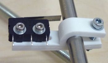
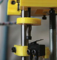
Mechanical Endstops are the most basic form of endstops, made of an ordinary switch, two wires. Changing the switch state signals the electronics.
 |
|
Optical
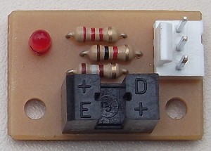
These Optical Enstops observe the lightlevel and reacts to sudden changes.
E.g: Gen7 Endstop and Opto Endstop.
Magnetic
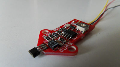
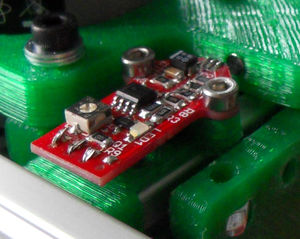
These endstops; Hall effect sensors is a transducer that varies its output voltage in response to a magnetic field. Hall effect sensors are used for proximity switching, positioning, speed detection, and current sensing applications.(--Wikipedia)
E. g: Hall-Θ.
Endstop Testing
No matter which type of endstop you use, it should be recognized by your electronics. Test procedure:
- Turn on your electronics/printer.
- Connect.
- Send
M119manually. - Firmware should report back status "0" or "open".
- Engage the endstop by pressing the switch, putting cardboard into the light barrier, etc.
- Send
M119again. - Firmware should report "1" or "triggered" or "closed".
Your endstop works if both reports are as expected.
Endstop Troubleshooting
- Endstop shows no reaction at all.
- Measure the endstop signal on the cable connector plugged into your electronics or, even better, the CPU's signal pin. It should swap between < 1 V and > 2 V. If not, it's a wiring or electronics problem.
- Signal voltage changes, but M119 reports always the same.
- Then your firmware is misconfigured. Likely it reads the wrong CPU pin. Another possible cause is, you plugged your endstop into a different header.
- Endstop shows the opposite of the intended reaction.
- If your endstop reports "closed" while being untouched and "open" when engaged, the signal is interpreted the wrong way. On mechanical endstops you can change the wiring (see Mechanical Endstop). Common to all endstop types is, you can invert signal interpretation in your firmware (config.h, configuration.h, etc.).
- Endstops are generally unreliable.
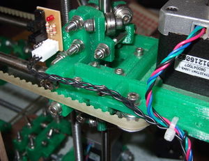
- Especially when bundling endstop wiring with stepper motor wiring, there's quite a chance signals get induced "out of nowhere". Braiding or twisting these two or three wires helps enourmously (for reasons a bit too complex to explain here):
|
| Braided endstop wiring on a Sells Mendel. |
- Triggering one endstop changes report of two or three of them.
- First of all, while wiring up endstops it doesn't matter what unused ones report. The reason why unused ones change is, if their signal pin is totally disconnected, it picks up electromagnetic noise or whatever, making the signal pretty much random or even following another one.
- You should correct this before running the printer, though, e.g. by disabling unused endstops in your firmware. Most firmwares make assumptions depending on which endstops are enabled and which not. For example, firmwares do homing movements only for axes with endstops.
