Filament Jamming Detection/ru
|
English • العربية • български • català • čeština • Deutsch • Ελληνικά • español • فارسی • français • hrvatski • magyar • italiano • română • 日本語 • 한국어 • lietuvių • Nederlands • norsk • polski • português • русский • Türkçe • українська • 中文(中国大陆) • 中文(台灣) • עברית • azərbaycanca • |
The intent of this document is to show one way of detect filament jamming/stopping using various
methods or some variations. One priority of the method is keep the costs as low as possible and
with less change in procediments and firmware as possible.
The detection method uses information of the filament itself and do not uses any of extruder
moving parts to take its actions and can detect either end of filament, filament jamming inside
nozzle, extruder slipping, knot in the spool and more.
The basic detection system reads filament motion using a little friction with the filament and
using this to drive a encoder wheel. If for any reason the filament stop moving the encoder will
stop turn and the firmware can detect the problem and take some action.
As the intent is to keep all changes at minimum to the actual hardware and software, the detector
is designed to be modular and independent - although it is still possible to integrate with the
extruder mechanism for space optimization.
I am separating the mechanism in three parts: mechanical detection of movement, sensor readings
of the data and firmware interpretation of the readings.
Contents
Mechanical detection of moving
Mechanical detection uses friction with the filament to detect its movement. This friction must
be as low as possible so as to require minimal torque from the extrusion mechanism and prevent
changing any other characteristics of the actual build of the printer.
The core function is based on a friction wheel using teeth or some plastic/rubber material which
will be forced to move with the filament. This movement is transferred to an encoder wheel with
or without a gear system and then read using either an optical or mechanical endstop. Also, any
system which can read movement from an encoder wheel can be used.
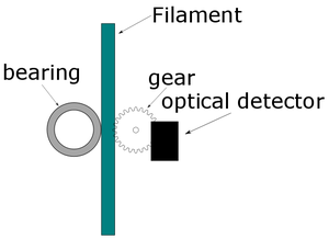
In above example I used a gear touching the filament in same way many extruders work and using a
bearing to keep the correct pressure and then read the gear movement using an optical endstop
which triggers with each gear teeth passing through it.
There are many other possible approaches such as but not limited to the use of a rubber piece or
another similar material to move the wheel along with the filament and/or use gears to translate
the wheel move to an encoder or yet use other methods as mechanical endstop to trigger the
encoder movement. (see Image 3)
Sensing the Movement
The second part is to use the mechanical data to get some electrical signal to the firmware. This
can be achieved either using an optical detector, mechanical detector or electric effect sensor,
such as hall effect or electrical resistance (potentiometer/trimpot) attached to the wheel, which
trigger an electrical signal to the control board.
See below various ways of detect:
- Use an optical endstop to read the gears or the encoder wheel;
- Use an mechanical endstop to read the gears or de encoder wheel;
- Use hall effect sensor to detect the movement of the gear or wheel by sensing electrical
current change in detriment of the wheel movement or position;
- Use electrical voltage variation to detect the actual position or movement of the wheel (as
much like some servo motors work)
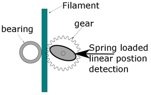
- Use position variant readers to detect physical linear position (see image 2)
After the movement have been detect this signal must be send to the control board or its movement
control section/chip/controller. This board or section will be called as “board” in the rest of
this document to keep it simple to read.
Firmware interpretation of Data
After the signal arrives the control board the firmware must manipulate this data despite of the
format of the signal, which can be either digital or analogic.
In firmware there are two possible ways to track the position. The easy way is simple compare the
movement of the extruder axis with the feedback and check if they are reasonably compatible but
not necessary identical. Other way is count each step of the input format and keep precise
feedback control. At this point all above problems can be detected and actions be taken. Despite of different
nature of all above mention problems not necessary all them are distinguishable and the firmware
must consider this fact.
The first and immediate problem that can be detected is the filament stop, which can be either
the end of filament, the extruder jamming, the extruder slipping or knot in the spool. This cases
the print can be paused and the user can fix the problem avoiding the loss of what has been
printed so far. A second problem is the extruder motor skipping steps. In that case, the precise read of the
position can be used to compensate this and temporarily fix the problem and avoid the lose of
what was already print. Note that a parcial jamming will grind the filament and cause the same effect of the extruder
motor skipping steps, then it causes the same effect and is detectable.
Each firmware “has” to be studied to avail the possibility of this implementation as long as its
requirements and necessary considerations.
Repetier Firmware already has most of this implemented as: FTS - Filament Tracking System and
more info can be found at:
Gallery of Images
Files and Resources
My version is using rubber wheels from an old desktop ink jet printer, some small bearings,
printed parts, M3 screws and nuts.
Work to be done
Implement a test version on some firmware
This document
This document is double licensed and is also licensed under Creative Commons Attribution for
RafaelEstevam and was first written in September of 2016 by RafaelEstevam. The original
version can be found here:


