HintsForUsingTheStratasysDimensionRPMachine
-- Main.EdSells - 07 Dec 2005
Contents
Design for RP manufacture on the Stratasys Dimension
SUMMARY
This page contains two features:
1) The download for the full 30-page manual which will walk you through the concepts required to design efficiently for RP manufacture on the Stratasys Dimension Rapid Prototyping machine.
2) A display of the quick-reference pages. Although this is found contained in the manual download, it is used so frequently during design that it might be useful displayed here.
1. MANUAL DOWNLOAD
Click on the link below to download the full manual:
File:HintsForUsingTheStratasysDimensionRPMachine-DesignforRPmanufactureStratasysDimension.doc
or if you need design data fast, check the next section...
2. QUICK REFERENCE DATASHEETS
General points
This data sheet has been designed to accompany the RP Manual - Design for RP Manufacture (Sells, 2005). This data only applies to the Biomimetics Stratasys Dimension machine at the University of Bath, UK.
- Walls should be at least 0.4 mm thick - this is 99% reliable! There have been no recorded failures at 0.6 mm.
- The ABS is quite flexible at thicknesses below 3 mm. However, when designing springs it is important to build them in an orientation which ensures that the stress runs along the length of the layers rather than over the weaker interfaces between the individual layers.
- Inverse drafts (overhangs) may range from 0 ° to 45 ° without requiring support material.
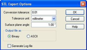
- When saving as an STL file click 'Options' and ensure parameters match those specified in Figure 1. Failure to do so, whether changes to the dialogue are made or not, might result in the creation of a very small STL file.
Figure 1: STL export parameters
- To save an assembly as a STL file Open a new part file Click 'Insert' on the top menu bar Click 'Part copy' Select required assembly (if not shown ensure 'files of type' is correct) OK
- Check STL magnitude in Catalyst using F9 and F10.
For circuit inclusion design:
- A typical profile for a casting channel is 1.6 mm wide by 2.0 mm deep.
- Casting channels incorporated into rapid prototype design should be at least 1.1 mm wide.
- Fences can be positioned as close as 0.2 mm to the primary component and still be easily peeled away.
RP hole diameter for true (non-RP) shaft:
Table 1: Simple metrics for designing RP hole diameters to achieve specific fits to true shaft diameters
| Fit type for hole and shaft | Design compensation for hole Ø (mm) (add to shaft Ø) |
| Interference fit | +0.1 |
| Tolerance fit | +0.3 |
| Clearance fit | +0.4
|
E.g. Hole Ø required for a clearance fit to a steel shaft, true Ø 8.00 mm. Design hole Ø at 8.00 + 0.4 = Ø 8.4 mm.
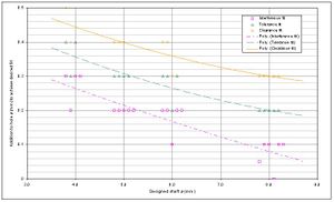
RP hole diameter for RP shaft diameter:
Figure 2: Mapping for fits between RP shafts and RP holes
E.g. For an RP hole to give a tolerance fit on an RP shaft designed at 6.0 mm, the hole must be designed at Ø 6.27 mm.
RP hole diameter for self tapping screws:
Table 2: Hole compensation reference table for screw fits
| Screw gauge | Tapping hole Ø (mm) design | Clearance hole Ø (mm) design | |
| 10 | 4.4 | 5.2 | |
| 8 | 3.8-3.9 | 4.8 | |
| 6 | 3.3-3.4 | 4.0 | |
| 4 | 2.6 (estimate) | 3.2
|
E.g. For a gauge 8 self tapping screw the tapping hole should be designed at Ø 3.8 mm and the clearance hole should be designed at Ø 4.8 mm.
RP hole diameter for metric taps:
Table 3: RP hole diameters for metric taps
| I.S.O. Metric coarse thread | Tapping hole Ø (mm) on the RP machine | Clearance hole Ø (mm) | |
| M3 | 2.8 | 3.4 | |
| M4 | 3.6 | 4.4 | |
| M5 | 4.5 | 5.4 | |
| M6 | 5.3 | 6.4 | |
| M8 | 7.1 | 8.5 | |
| M10 | 8.8 | 10.5 |
E.g. For a M6 bolt the tapping hole should be designed at Ø 5.3 mm and the clearance hole should be designed at Ø 6.4 mm.
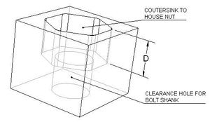
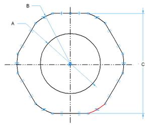
RP countersink to house a metric nut
| * | *A | B* | *C | *D* |
| I.S.O. Metric nut | Clearance hole Ø (mm) | CS rounding Ø (mm) | Hexagonal flat dist (mm) | CS min depth for flush nut (mm) |
| M3 | 3.4 | 6.3 | 6.00 | 2.4 |
| M4 | 4.4 | 7.9 | 7.45 | 3.0 |
| M5 | 5.4 | 9.3 | 8.45 | 3.9 |
| M6 | 6.4 | 11.5 | 10.45 | 5.0 |
| M8 | 8.5 | 14.8 | 13.35 | 6.3 |
Note: Retaining nut characteristics for the above rounded-hexagonal profile only work when the profile is in the horizontal plane on a Stratasys build: if support material is required, the push fit will usually not be achieved. However, the flats from a vertical plane build will still successfully constrain the nut from spinning.
Support material awareness
As explained in Section 1 of the full manual, support material will be induced for overhanging features. Support material should be avoided if possible as it will improve the efficiency of the build, improve the finish of the component and save time finishing the component post manufacture.
Please read the relevant section in the manual to avoid the use of support material where possible during a build.


