InvoluteProfile1
Contents
Designing Involute Profile Gear Pairs in Art of Illusion
Background
Caveats
This tutorial assumes that you have a basic acquaintance with the workings of the Art of Illusion (AoI) 3D Modelling Programme.
Designing a Gear Pair
Designing a gear pair with the Involute Profile Gear script in the AoI is really quite easy.
Suppose that you want to design a 3:1 ratio gear pair. Using the 3:1 proportion you then need to apply that proportion to deciding the radii of your two gears. If you choose your smaller gear to have a radius of, for example, 25 mm your larger gear should have a radius of three times that or 75 mm.
On AoI you should enter the radii in millimetres or 75:25. Now you need to similarly decide how many teeth there should be on your gear pair. If you choose 7 teeth for your small gear, your large gear should again have three times that or 21 teeth.
The Involute Profile Gear script can currently create gears with an upper limit of 50 teeth and a lower limit of 4.
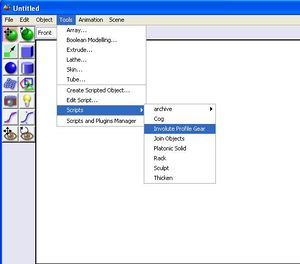
To begin, from inside AoI you bring up the Involute Profile Gear Script. On the AoI taskbar click on Tools, select Scripts on the drop-down menu and then select Involute Profile Gear off of the Scripts menu.
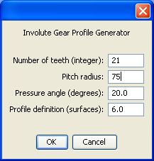
A data window for the script will appear. Enter the radius and tooth count for your larger gear.
Please notice that you have a Pressure Angle set to 20 degrees. Ordinary industrial practice uses gear pressure angles of 14.5 degrees and 20 degrees. While the script will let you explore a wider range of pressure angles than this it is not recommended at this time that you attempt to design gear pairs with non-standard pressure angles.
You will also notice that the script defaults to using six surfaces to define the involute profile. It is not recommended that you use less than this number of surfaces. Using more than six can seriously slow the time required to process the gears.
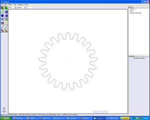
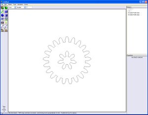
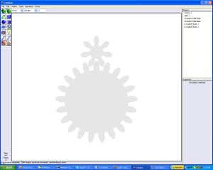
Once you hit the OK button your gear profile will appear thusly.
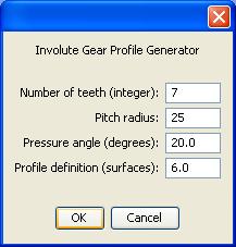
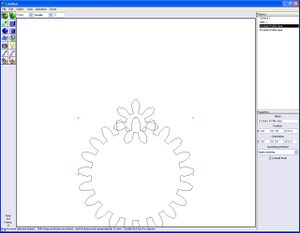
Now enter the radius and tooth count data for your smaller gear.
Now you have your large and small gear profiles to work with.
Unless you are very sure of yourself you should check to see that your gear pair meshes. It is easy to do this with odd-numbered tooth count gears. First, look at the Objects list on the right-hand side of your AoI work window and click on the larger gear profile.
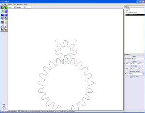
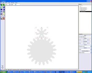
Now that you've clicked on your gear look at the Properties list that appears just below it. In AoI the y axis is the vertical axis. Enter the Pitch Radius value of the gear (75) in the Y value of the Position vector.
Doing that will lower the large gear.
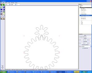
Repeat the process with the small gear. You can now visually confirm that the gear pair mesh.
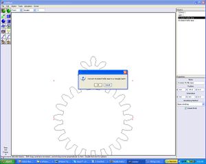
You must remember that so far you've only have created the profiles of the gears. Now you have to fill them with a triangle mesh. Select your gear again in the Objects list and right click. You will see a menu appear. In it select Convert to Triangle Mesh.
This action will bring up a window inviting you to convert the large gear profile to a triangular mesh. Click on OK. Depending on the speed of your PC and the number of teeth in your gear this process can take a while. Be patient.
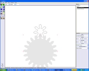
When the process is complete the large gear will darken. Repeat the process with the small gear.
Now that you have turned your gear profiles into surfaces, you must now turn them into solids. You do this by extruding the gear surfaces.
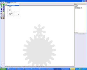
To do this pulldown the Tools menu and select Extrude.
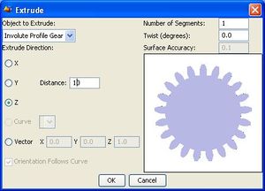
This will bring up a data window for the extrusion process. Don't try to do anything until a small picture of the gear appears on the window. This is VERY important.
The Distance measure gives the thickness of the gear. The default value is 1 mm. Set it to 10 mm for this example. Again don't try to do anything until your mouse cursor returns to an arrow shape. Once that happens, click the OK button. Repeat this for the small gear.
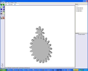
To take a look at your gear pair, look at the icons on the left side of your AoI window. Notice the two eye icons at the bottom of the stack. Click on the one with the curved arrow on it.
Move it slightly to look at your gear pair in 3D.
You can now proceed to use the Boolean Modeling option in the Tools menu to remove excess volume from your gears and do things like create holes in them for shafts and the like.
You can download the script from [[File:InvoluteProfile1-InvoluteProfileGear.bsh. Save this file into the Tools folder of the Scripts folder in the main folder for Art of Illusion. If you are running AoI when you do this you will have to close AoI and restart it to be able to see the Involute Profile Gear option in the Scripts option of AoI.|thumb]]
-- Main.ForrestHiggs - 08 Sep 2006
