MaKrPanel
Release status: working
| Description | Release Version 1.0
|
| License | unknown
|
| Author | |
| Contributors | |
| Based-on | [[]]
|
| Categories | |
| CAD Models | |
| External Link |
Contents
Introduction
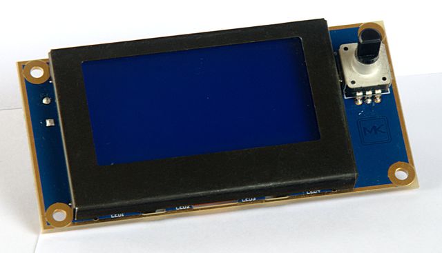
The MaKrPanel features a blue graphical LCD with white backlight, a microSD, switch encoder and a buzzer. It can be fitted to most existing 3D printer controller boards.
For availability please check out this ongoing campaign on ulule.com. The panel is sold for 35/39€.
Description
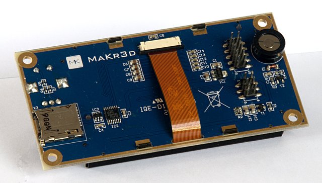
This panel adds a convenient user interface to the printer hardware to allow for stand-alone printing from a micro-SD card. The PCB matches the mounting holes on the MaKr Melzi board. Using the included screws and spacers the panel and board can be assembled to one compact unit without big cable mess.
The display contrast is fully software-controllable, no need for a contrast adjustment poti. The backlight can be switched on and off using any digital output signal. If connected to a PWM capable output, dimming is possible.
Electrical connection
The LCD is connected to the CPU using a unidirectional SPI connection. In addition to the usual SPI signals /Reset, SCLK and MOSI the LCD needs two additional output signals for LCD_A0 (or LCD_RS) and LCD_CS.
The SPI signals are connected using the regular 6-pin Atmel ISP connector and the additional two lines for LCD_A0 and LCD_CS are connected using an additional 10-pin connector. Both pin header, the 6-pin and the 10-pin, are arranged in a way that they can be contacted using a single 20-pin connector with four unused spare pins in between.
The detailed pinout is as follows (seen from above, to the pins, with the empty space in between the two connectors):
/LCD_CS   1  2  LCD_A0
ENC_SW    3  4  Beep
ENC_A     5  6  Backlight
ENC_B     7  8  SD-SS
Vcc +5V   9 10  GND
          .  .
          .  .
MISO      1  2  Vcc +5V
SCLK      3  4  MOSI
/Reset    5  6  GND
Software support
The Marlin firmware already includes support for ST7565-compatible graphical LCDs. To activate it, uncomment this #define in the Marlin/Configuration.h file:
// The MaKr3d Makr-Panel with graphic controller and SD support
// http://reprap.org/wiki/MaKrPanel
#define MAKRPANEL
For the MaKrMelzi a valid pin mapping is already included in the sources. For all other controller boards you need to provide pin mappings in the file pins.h for these signals (replace the pin numbers for your actual pin numbers):
// Pins for DOGM SPI LCD Support
#define DOGLCD_A0  30
#define DOGLCD_CS  29
// GLCD features
#define LCD_CONTRAST 1
// Uncomment screen orientation
   // #define LCD_SCREEN_ROT_0
   // #define LCD_SCREEN_ROT_90
#define LCD_SCREEN_ROT_180
   // #define LCD_SCREEN_ROT_270

// The encoder and click button
#define BTN_EN1 11
#define BTN_EN2 10
#define BTN_ENC 16  //the click switch

// The SD card
#define SDSS 30
A Programming tutorial for a similar module: [1]. Please note: The adafruit display used in this tutorial has a different page mapping. For use with our module you need to modify the pagemap by editing this line in the file c/stlcd.c:
int pagemap[] = { 7, 6, 5, 4, 3, 2, 1, 0 };
An Arduino library for the DOGM128, another software compatible ST7565R-based display: [2]
Technical Details
- LCD resolution: 128 x 64 pixel
- Display: white/blue (blue background, active pixels white), black metal frame
- Visible area of the LCD: 55 x 27.48 mm²
- Pixel size 0.39x0.39mm²; Total pixel pitch 0.43mm
- LCD controller: ST7565R, SPI protocol
- Encoder switch with press button, 24 clicks per round
- Buzzer
- MicroSD slot
- 5V/70mA at full backlight brightness plus up to 100mA for the microSD card
- all external signal at 5V TTL levels, no 3.3V level shifter or voltage regulator required.
- Connects to the 6-pin Atmel ISP connector and another 8 digital lines
- Total size: 50 x 98 mm²


