Mendel90 Build Manual
This page explains how to DIY build the Mendel90. For the latest instructions for the kit version see [Mendel90_Dibond.pdf]. This is also worth reading when building other versions because it is always up to date.
Contents
Getting The Code
The Mendel90 design is implemented in OpenSCAD and is available on GitHub. The OpenSCAD files have to be compiled to produce the Bill of Materials (BOM), drill sheets, 3D models etc. There are several reasons why it is a very good idea to download and compile it yourself:
- The design is still being tweaked; having a local copy means you are guaranteed to be still building the same machine at the end as you are at the start;
- You can compile and view a 3D rendering of the sub-assemblies to help you know what goes where at each stage of the build;
- You can change the design to suit your needs (e.g. make it bigger or smaller).
To build the design you will need OpenSCAD, Inkscape and (optionally) Blender. Be sure to read the README.txt, which gives minimum version requirements for OpenSCAD. There are two working designs - the "mendel" version has an acrylic frame, and the "sturdy" version is MDF.
The file scad/conf/<machine>_config.scad has a number of changeable parameters, including the size of machine you want. Parameters you may want to tweak are:
- base: the material used for the base (see sheet.scad for the available options)
- frame: same for the frame
- Y_carriage: material for the Y carriage
If you have your parts printed by anyone other than Nophead, or using nozzle size/layer height parameters other than the default, those will also need to be changed in here.
Getting Your Parts
Once you have a BOM (either built or downloaded) for a machine you are happy with, you will need to source your parts. See the Mendel90_Buyers_Guide.
General Build Tips
- The instructions below are not at the "put screw X into hole Y" level of detail. The best thing to do is download the code, edit scad/conf/config.scad to set "exploded" to "true", load the file for the particular sub-assembly you are working on into OpenSCAD, and render it (F5). You can normally fairly easily work out which items on the individual sub-assembly BOMs are which items on the rendered image, and the instructions below should complete the picture and allow you to assemble each part. If you want to print it and scribble on a copy, OpenSCAD has an "Export as Image" option.
- All screws have a plain washer where they meet the plastic, to spread the load and prevent the plastic being chewed up by the rotation of the screw head. Most fixings have a captive Nyloc nut to prevent them vibrating loose. You can use plain nuts but in that case you should add a star washer between the screw head and the plain washer. The screws into the panels have star washers for the same reason.
- Washers tend to have a smooth side and a side with a burr from being stamped out. Make sure the smooth side faces bearings and belts.
- Chamfer the ends of the smooth rods with a file to remove any burr, otherwise they can knock the balls out of the linear bearings.
- Parts which have holes in surfaces where there is nothing underneath have a support membrane that needs removing. The 8mm holes in the X ends and Wades block plus the rectangular hole in the top of the X motor bracket are best removed with a small knife. The smaller holes in the Y belt anchors, Z couplers and the X carriage are best cleared with a 3mm drill.
Tools
Required
- Drill, with various bit sizes (depending on frame material - see drill sheets)
- Long Pozidriv screw driver
- Allen keys: 1.5mm (for M3 grub screw), 2.5mm (for M3 cap head) and 3mm (for M4 cap head); also electric screwdriver bits to save you time
- Spanners: 5.5mm (for M3 hex bolts) and 7mm (for M4 hex bolts); some bolts are hard to access so only a spanner will do, but nut drivers will save you time for others
- Wire strippers
Optional
- Small screw driver for Melzi terminals (if using Melzi electronics)
- 75mm holesaw or coping saw (if fitting fan)
- Hairdryer for heating recalcitrant plastic
A powered screwdriver with variable torque will make your life a joy. Use minimal torque for bar clamps, maybe 50% for DiBond (do a test if you have a spare piece; if the washer bends the aluminium, it's too much) and maybe 70% for MDF or printed plastic.
Sheet Parts
Mendel90 have been made successfully from MDF, Acrylic, Polycarbonate and DiBond.
You can cut the frame parts out of a sheet of MDF with just simple tools, or ask your local DIY store to do it if they have the facilities. The original sheet very likely has pretty square corners, so cut the parts in such a way that the original square corners of the sheet are in the most important spots. A sheet of MDF of 2 by 4 feet (61x122cm) is enough for a Mendel-sized Mendel90.
MDF absorbs water, and so can change size by a millimetre or two in different humidities. To avoid this, and make your machine look nicer, you might want to paint it using acrylic paint. Beware, though, this is a big job. I (Gerv) used spray paint, and had to do two coats on both sides, plus the edges, outside on plastic, while dodging the rain! It took two full cans of paint. Paint before drilling.
Alternatively, for a very nice, professional appearance when finishing MDF, apply a very thin coat of drywall compound to the edges. After it dries (leave it overnight), sand the edges smooth. Prime the MDF, then after the primer has dried, paint it. The Krylon brand spray on primer and paint work very well. An alternative is to use 2-3 coats of de-waxed shellac, lightly sanded between coats, if you don't mind a dark brown finish. Wear appropriate breathing protection/goggles. Paint in a ventilated area away from pilot lights, etc.
Drilling
The PDF files in the sheets/ directory contain marked positions for all holes to be drilled. These PDFs are larger than normal-sized paper (A4 or Letter), but can be printed on such paper with cut marks. To print a file in this way using Adobe Reader: open the PDF, select: File -> Print. Choose "Poster" and select "Cut marks". This will print the drilling guide on a number of sheets of paper which can easily be glued or taped together. Cut out the corners of the sheets that are on top exactly along the cut marks so that the cut marks of the sheet below can be lined up exactly.
If you use only Free software and so are not a fan of Adobe Reader, convert to PostScript using Inkscape, and then use the "poster" tool to split into sheets of your system's standard paper size.
 inkscape -f frame_base.svg -E temp.eps
 poster -s 1 temp.eps > frame_base.eps
 ps2pdf frame_base.eps frame_base.pdf
Another option is to get a print shop to print the drill templates in one piece on a larger piece of paper - although this can be expensive. I thought sticky-backed vinyl, which the local print shop offered to print on for me, would be a great material for printing one-piece drilling guides on, because I could stick it to the sheets. However, it turns out it doesn't peel well off painted MDF, and I was there for a long time with the glue remover. You might do better if using DiBond or acrylic.
The drill templates go on the top of the base, the front of the gantry and the left side (as you look at them) of the stays. When aligning the drill templates, the crucial distance for the smallest holes on the stays and gantry (for the fixing blocks) is that from the edge of your material, not from any other holes. For the base, it's their relationship to each other that's most important.
When drilling MDF, make sure you drill into another piece of wood rather than free air. Drilling into free air will make a mess of the exit holes. This looks particularly bad if you've painted the MDF.
There are some holes you may not want to drill, depending on which configuration you are building:
- The fan holes, which is the 75mm hole in the left frame support, plus the four fixing holes immediately surrounding it.
- The bottom Z limit switch bracket holes (if you are using a top Z limit switch), which are the two 1/3 of the way up the very left side of the gantry. There's also a hole for its wire, the larger hole directly above the left Z motor bracket.
- The holes for mounting the electronics in the right frame support, if the design does not support your electronics. (You will need to drill alternative holes).
There are some additional holes you may want to drill:
- Holes for your electronics, if not using the default holes.
- Holes to mount your PSU. You'll need to figure out the best way to mount this, making sure the fan and grilles are clear and the switch and wires are accessible.
Frame Assembly
Refer to frame_assembly.txt for the parts list. If there are two screw lengths then the longer ones go in the base. Each screw should have a star washer on top of a plain washer.
- Attach three fixing blocks to the left and right stays with two screws each, noting that they go on the side that faces inwards. Stand the sheet on its edge on a flat surface and slide the block down to be flush with the edge before tightening the screws.
- Fit the remaining four fixing blocks to the back of the gantry in the same way.
- Fix the stays to the gantry using one screw in each fixing block from behind. Use the slots to align the stay vertically although that isn't critical.
- Screw the gantry to the base with six screws. Align the stays with the back edge before tightening.
- Loosely attach the five cable clips, as follows:
- The biggest one, for the bed wires, goes in the hole 5cm or so from the back back of the base, just right of centre.
- The two middle size ones, for the Z motors, fan and limit switch, go on the back of gantry at the edge of the central division just below the top fixing block, next to the holes in the stays.
- The two small ones, for the Y motor and limit switch, go on the right hand side of the base, in line with one another just inside the arch, one about 9.5cm from the front, the other just beyond the arch.
- Orient the cable clips to match the wires holes.
- Loosely attach the two ribbon clamps. The longer one (37mm centre-to-centre) goes at the back of the base for the bed wires. The shorter one (34mm centre-to-centre) goes at the top of the gantry for the X axis cable. To ensure they move smoothly on the screws, you may want to drill out the holes to 4mm.
Bed Fan Assembly
The fan is optional. It is used to cool the bed rapidly at the end of a build so that the parts can be removed quickly. Refer to bed_fan_assembly.txt for the parts list.
Make sure the fan is blowing inwards. This is usually indicated by an arrow on the frame and is often the side with the label.
The four screws pass through a plain washer, the fan guard, the left stay, the fan and finally a nyloc nut. There isn't a washer behind the fan because fan frames tend not to have room for one.
Z Axis
X Idler End
Using the parts in x_idler_assembly.txt assemble the X idler end. The relevant SCAD file is x-end.scad, although you will need to change the final rendering call at the bottom to be:
x_end_assembly(false);
Remove the support material in the nut traps with a drill or a small penknife. Also remove any loose filament created by the overhanging dividers in the bearing channel.
To insert the linear bearings it is easiest to push the end which is towards the middle in first. Then slide it up against the divider in the middle before pushing in the other end. Insert a rod to check they are aligned well. If pushing them in is difficult, a minute's application of a hairdryer on the hottest setting will soften the plastic.
It can be easier to pull the M3 nuts for the bar clamps into their hard-to-reach traps using one of the longer screws from elsewhere in the design.
Leave the long bolt that forms the idler axle loose to allow the X bars to be inserted later.
X Motor End
Using the parts in x_motor_assembly.txt assemble the X motor end. The relevant SCAD file is also x-end.scad; in this case, the final rendering call needs to be:
mirror ([1,0,0]) x_end_assembly(true);
You will need to remove support material from the vertical channel here also. Don't fit the limit switch now, leave it to the wiring stage. The motor is best fitted later as well due to its weight.
Z Motor Assemblies
Using the parts in z_motor_assemblies.txt assemble the two motor assemblies. The relevant SCAD file is z-motor-bracket.scad.
- Drill out any support material in the Z couplings using a 3mm drill.
- Degrease the motor shafts before fitting the plastic tubing but be careful not to degrease the bearings. Fit the coupling loosely over the tubing. The plastic tubing will also be a very tight fit; again, application of a hairdryer may help.
- Twist the motor wires in pairs and feed them through the hole in the gantry before attaching the motor assemblies. See below for the best way to do this.
Z Axis Assembly
Using the parts in z_axis_assembly.txt assemble the Z axis. If you want a rendering, you will need to render main.scad to see it.
- Fit the top bar clamps, note that the one with small screw holes for the limit switch goes on the left and they both face the same way.
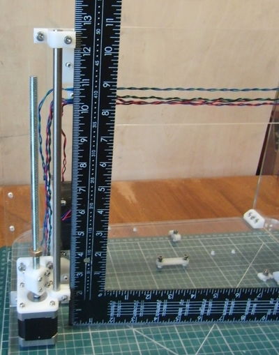
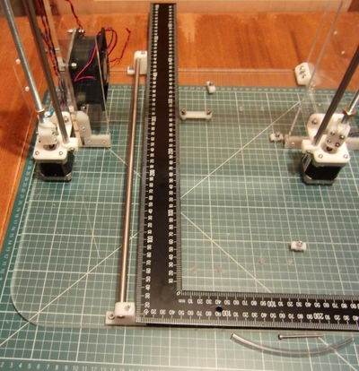
- Temporarily inset the left Z bar and use a large set square to ensure the left hand Z bar is vertical. The clamps at the top and bottom of the bar are identical so they can be aligned rather than the bar itself. Leave the right hand top clamp loose until the X axis is fitted.
- Fit the top Z limit switch. This is optional but recommended instead of a bottom switch.
- Fit the Z bars, inserting them through the X ends.
- Finally fit the lead screws by screwing them though the X end M8 nuts and the Z pointer. You may find it easier to thread on the X end nuts and then the Z pointers (which can be a bit stiff) before insertin them into the X ends from below. This will work if you run the X ends all the way up to the top.
- Once they are in, secure them to the motors using the couplings. You can assemble the couplings, loosely screwed together, before putting them in place.
Y Axis
Y Carriage Assembly
The parts list is in y_carriage_assembly.txt. The relevant SCAD files (for part) are y-belt-anchor.scad and bed.scad. Seeing the entire thing requires rendering main.scad.
- The edge of the carriage with two holes in the middle is the back and the side with most holes is the left.
- Use one washer on each side of the carriage for everything. In all cases except the cable clamps, the nuts go on the bottom and the screw heads on top (otherwise the heat shield is too thin for the projections). The cable clamps have the heads on the bottom to avoid a clash with the Y idler.
- Tie the bearings into the holders with the zip ties, and screw the holders to the carriage using M4 screws. Note that one of the bearing holders has a tab to trigger the limit switch. That goes on the right hand side with the tab facing forwards.
- Align the two bearings on the left by inserting a rod and lining up the tabs with the edge of the board before tightening the screws. Leave the third bearing loose.
- Drill the support material out of the belt anchor holes with a 3mm drill and insert the captive nuts. A long M3 screw can be used to pull them up to the top. If they are too tight, one option for loosening them is to thread a nut onto a long M3 screw and gently hammer it in "backwards" to widen the hole before pulling it out using a claw hammer and then pulling it through forwards!
- Fit the belt clamps loosely to retain the nuts (don't forget washers), then fit the anchors to the carriage using M3 screws. Note that the anchor with the tooth goes at the back and the belt clamp with the tooth at the front.
- Fit two wide ribbon clamps to the holes at the back of the board, both facing inwards, using M4 screws. The washers go next to the screw/nut, not the carriage.
Y Axis Assembly
The parts list is in y_axis_assembly.txt. The relevant SCAD files (for part) are y-motor-bracket.scad and y-idler-bracket.scad.
- Insert the captive nuts and clamp screws in the Y bar clamps.
- Loosely fit the two left hand Y bar clamps to the base. Orient them so the rods are on the outside.
- Fit the long Y bar temporarily and use a large set square to make it perpendicular to the base sheet before tightening the base screws.
- Solder the wires on the Y limit switch and screw it to the bar clamp before fitting it front right and the other back right. Leave the right hand bar clamps loose.
- Fit the Y motor to its bracket, noting the wires come out of the face facing the back, and then fit the bracket.
- Assemble the Y idler assembly (y_idler_assembly.txt) but don't screw it to the base. See a rendering of main.scad for the ordering of washers.
- Thread the belt (the smaller of the two) through the idler (the right way :-) and attach both ends to the carriage noting the half twist. The ends of the belt should project 7.5mm, i.e. two teeth and a gap or a little over, when viewed from the side.
- Slide the Y bars into the carriage and the base, and slide the carriage up and down to align the right hand bearing and bar clamps. Tighten the bearing first and then move it to each end and tighten the clamps.
- Put the belt over the pulley and fasten the idler assembly to the base with enough tension on the belt to play a low note when plucked.
Y Heat Shield
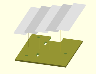
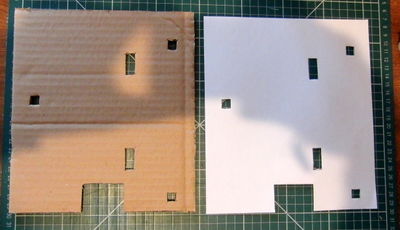
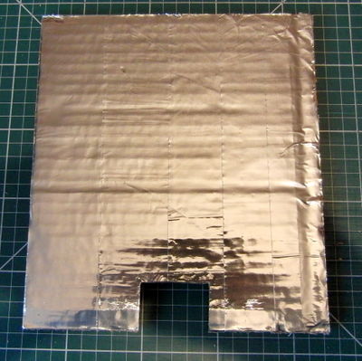
The heatshield prevents heat radiating downwards from the bed heating the Y carriage, which can make it warp due to the top surface expanding more than the bottom. 6mm corrugated cardboard is used as a cheap and effective insulator and aluminium foil tape on top reflects heat back towards the bed.
Start by printing a paper template from the pdf drawing https://github.com/nophead/Mendel90/raw/master/mendel/sheets/y_heatshield.pdf. Cut out the outline with scissors or a craft knife. Place the template over the cardboard and cut round with a straight edge and craft knife. Cut through the holes.
Apply the tape strips with some overlap. Turn it foil side down and trim round with a knife.
X Axis
X Carriage Assembly
The parts list is in x_carriage_assembly.txt. The relevant SCAD file is x-carriage.scad, which includes the extruder.
- Drill out the support material from the right hand nut trap with a 3mm drill.
- Insert the bearings and secure with zip ties noting the big end of the tie faces inwards.
- Attach the belt to the left side clamp with the teeth facing upwards and two teeth projecting from the clamp.
- Insert the captive nut and screw for the belt tensioner and put the tensioning piece on the end of the screw.
- Put one half twist in the belt and feed it though the slot below the right hand clamp with the teeth facing downwards.
- Double back the belt over the tensioner and clamp it with two teeth projecting.
X Axis Assembly
- Put the X ends at the bottom of the axis.
- Slide the X bars through the idler end, the X carriage and into the motor end.
- Tighten the X bar clamps while the axis is at the bottom. Don't over tighten them, i.e. don't close the gap entirely, just enough until you feel it grips the bar solidly.
- Move the axis to the top and then tighten the top right Z bar clamp.
- Fit the motor, pulley and idler. The motor wires should be in the top right quadrant, and come out the hole in the top.
- Put the belt in place and tension enough to play a low note when plucked.
Wade's Modified Extruder
The parts list is in wades_assembly.txt. The relevant SCAD file is wade.scad.
The wiki page on Wade's extruder has assembly instructions, including a graphical guide, for a standard Wade's. The differences are:
- Use of only two screws rather than four in the pinch wheel clamp
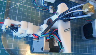
- Connecting all the wires to the D-sub connector (to attach the plastic frame, remove some of the motor screws and replace with others as specified in the BOM)
Tips:
- You may need to press the large bearings into the extruder block with a vice - they are a very tight fit.
- Don't forget to fit the hex bolt underneath the motor before fitting the motor, as you can't get it in afterwards.
- You can press the M3 nut into the slot in the small gear with a hot soldering iron; it will melt its way in nicely.
- Make sure you fit the small gear the right way round, so you can remove the large gear (which you will need to do to clean the extruder) without needing to remove the small one.
- The pinch wheel which presses the plastic against the hobbed bolt needs to rotate freely. If the slot in the main block is too narrow due to printing sag, you will need to sand it wider.
You can use "glass rope glue" to glue in the heater and thermistor. If you do, however, make sure to heat it to 90 degrees and leave it for an hour or two before using it for the first time, to give any water in the glue a chance to escape without blistering it.
D Connector
The parts list is in D_connector_assembly.txt. The relevant SCAD file is d-motor_bracket.scad.
- Again, pressing nuts into slots with a soldering iron works well.
- Make sure you get the two D connectors the same way round.
Wiring
Y & Z Axis Wiring
The motor wires should be tightly twisted in pairs to reduce RFI. The normal coil pairings for the recommended SY42STH47-1684A motors are red / blue and black / green. The easiest way to twist them is to tie a knot at the far end of the wire pair and spin it in the chuck of a drill with some tension on the wire.
The motors come with 2.5m of wire so it is best the cut them roughly to length before twisting them, but leave at least 0.5m spare to account for it getting shorter when twisted.
The spare wire can be used for the limit switches, fan and thermistor. Use two wires of the same colour to make them easily distinguishable from the motor wires and each other, e.g. a pair of black for the thermistor and a pair of green and a pair of blue for the Z and Y limit switches. (The X limit switch is wired directly to the ribbon cable.) They should also be twisted to reduce induced noise.
The wires should be soldered to the limit switches before the switches are fitted. Use the outer two pins, which means 'normally closed'. Note that the wire for the X limit switch has a dedicated hole in the X motor bracket, which is easy to miss.
There are three sizes of cable clip, each with two slots. The largest is for the bed and thermistor wires. The smallest is for the Y axis motor and limit switch. The middle size clips are for the Z axis motor + fan wires and the Z limit switch.
The clips keep the sensitive input wires away from the power wires and there are separate holes in the frame which line up with the clips.
Bed Wiring
The bed is connected via 400mm of 26 way ribbon cable.
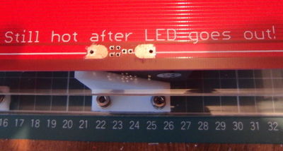
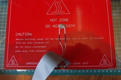
The pads on a v2 PCB heatbed are too small for the size of wire that is appropriate for the current, so remove some of the solder resist by scraping with a sharp blade. Scrape towards the edge to avoid the risk of damaging the finer heating tracks.
Block the holes on the back with some tape to prevent solder flowing through. Strip about 12mm of the outer twelve wires on each side and twist them tightly together and solder to the pads.
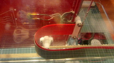
The middle two wires should be soldered to the thermistor leads. Keep the thermistor leads full length (because they are less thermally conductive than copper wires) and insulate them with PTFE sleeving. Use heatshrink sleeving over the solder joints.
Glue the thermistor to the underside of the bed using a thermally conductive high temperature glue such as JB-Weld, or tape it on with a high temperature tape such as Kapton, or the aluminium foil tape used for the heatshield. However, note that the aluminium foil tape is conductive, and so should not be used on uninsulated wiring. If using heatshrink to insulate your thermistor wires, check its maximum operating temperature and make that the max bed temperature in your firmware later.
Note that the ribbon cable leads off towards the centre of the bed initially and then curls back towards the edge. Put the cable through the top ribbon clamp on Y carriage and screw the bed to the pillars. Loop the cable back underneath the carriage through the bottom ribbon clamp and put the cable strip underneath it in the same clamp.
Slide in the heatshield from the front and fix it front and back with high temperature tape.
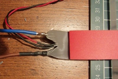
Terminate the ribbon cable just past the end of the cable strip as shown below. The thermistor connection can be made with left over motor wire. The bed wires should be 40 strands of 0.2mm, e.g. the individual wires inside 13A mains cable (40/0.2, 0.6mm^2, or AWG 18.)
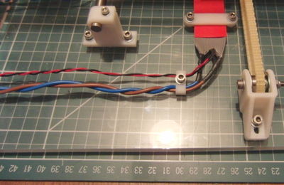
Fasten the free end of the ribbon cable and the cable strip to the base using the ribbon clamp. The strip should press against the cable to force it into a smooth loop. Use the cable clip to take the wires through a 90° bend and feed them through the holes in the right hand stay.
The suggested wiring sequence for least thermistor noise is : -
| Wire number | Signal |
|---|---|
| 1-12 | Heater - |
| 13 | Thermistor GND |
| 14 | Thermistor signal |
| 15-26 | Heater +12V |
X Axis Wiring
The X axis motor and the extruder are connected by a single 20 way ribbon cable. The following pin connections are used to minimise cross talk.
| Wire number | Signal | D type connector pin |
|---|---|---|
| 1 (red) | X limit signal | |
| 2 | X limit GND | |
| 3 | Thermistor signal | Pin 1 |
| 4 | Thermistor GND | Pin 9 |
| 5 | Spare | Pin 2 |
| 6 | +12V | Pin 10 |
| 7 | +12V | Pin 3 |
| 8 | +12V | Pin 11 |
| 9 | Heater - | Pin 4 |
| 10 | Heater - | Pin 12 |
| 11 | Heater - | Pin 5 |
| 12 | Fan - | Pin 13 |
| 13 | Extruder motor red | Pin 6 |
| 14 | Extruder motor blue | Pin 14 |
| 15 | Extruder motor green | Pin 7 |
| 16 | Extruder motor black | Pin 15 |
| 17 | X motor red | |
| 18 | X motor blue | |
| 19 | X motor green | |
| 20 | X motor black |
(The fan pin and wire is for if you want to add a cooling fan for printing overhangs; that's not part of the base build.)
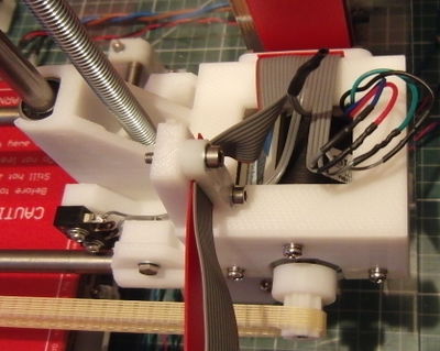
Start with about 1.5m of 20 way ribbon cable. Split off ways 3 to 6 and feed them through the smaller cable clamp in the X end. Solder those 14 ways to the female D-type connector or use an IDC version. Make the 14-way section just the right length (use the polypropylene strip to measure). Pull the other ways back to the X end. Leave the appropriate two long enough to go through the dedicated hole in the X end to the X limit switch, and cut the rest just long enough to connect to the motor.
Attach the ribbon clamp at the extruder connector to trap both the wire and the polypropylene cable strip. Form it into a loop to reach the extruder before tightening the ribbon clamp at the X motor end.
Make the connections to the motor and limit switch and then fit the switch.
Tuck the connected wires into the hole in the the bracket.
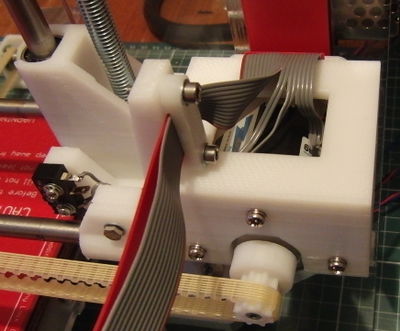
Fit the remaining polypropylene cable strip and tighten the two 20 way ribbon clamps. The ribbon cable goes over the top and down into the electronics bay where all the other wires terminate.
Connecting The Electronics
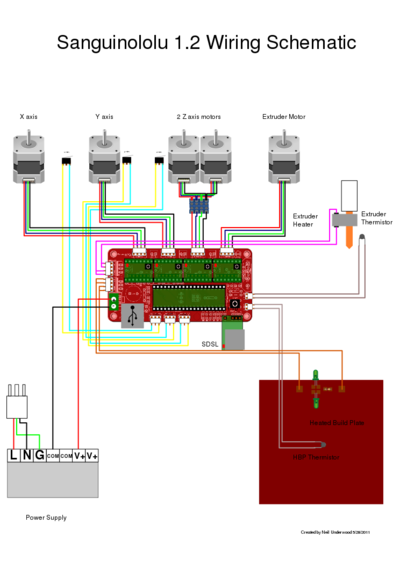
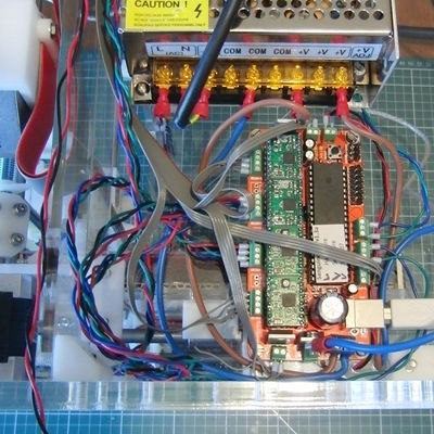
Fit your preferred electronics and connect all the wires. The example below shows a Sanguinololu connected as shown here:
Note:
- It could be a lot neater if the ribbon cable had not been cut too short and the other wires too long.
- The standard connectors have been replaced by screw connectors and ferrules as Nophead finds these more reliable.
- The X, Y and Z motors are wired in reverse compared to the diagram above because the motors are all reversed compared to a Prusa.
- The bed is connected directly to the +ve rail of the PSU and the tab of the MOSFET with a ring terminal to avoid the underrated connector on the PCB.
- There is nowhere for the fan to connect on a Sanguinololu. (See http://hydraraptor.blogspot.com/2012/07/sanguinololu-fan-hack.html )
- The mains connections to the PSU should be completely covered and the cable should have strain relief, TBD.
Extruder Wiring
The thermistor and heater wires should be kept at full length to minimise the temperature at the solder joints. PTFE sleeving and PTFE insulated wires are used close to the extruder to handle the temperature. Preferably the heat shrink sleeving should be silicone. The black heat shrink will degrade at hot end temperatures and can't be relied upon as insulation, so the heater joints are made inside the PTFE sleeving.
The extruder assembly (motor, fan, heater, and thermistor) are connected by a male D-sub 15 pin connector. The following pin connections are used match the X Axis Wiring.
| Signal | D type connector pin |
|---|---|
| Thermistor signal | Pin 1 |
| Thermistor GND | Pin 9 |
| Spare | Pin 2 |
| +12V | Pin 10 |
| +12V | Pin 3 |
| +12V | Pin 11 |
| Heater - | Pin 4 |
| Heater - | Pin 12 |
| Heater - | Pin 5 |
| Fan - | Pin 13 |
| Extruder motor red | Pin 6 |
| Extruder motor blue | Pin 14 |
| Extruder motor green | Pin 7 |
| Extruder motor black | Pin 15 |
Electrical Testing
To run your RepRap, you need firmware for your electronics. The instructions here may not be suitable for all boards and firmware.
First, you need to make sure that suitable firmware is loaded into the board. Sanguinololus tend to come with Sprinter installed; Marlin (a Sprinter derivative) is another option. nop head has his own Mendel90 fork of Marlin, although it's based on an earlier version. On Windows, the PC also needs a USB FTDI driver for the serial port to appear. If you don't have firmware, download some and load it according to the instructions page for your board on this wiki. The firmware will need some brief configuration before it will even start up properly - most obviously, defining the type of board you are using and the baud rate in Configuration.h. Note that non-standard baud rates have some problems on Linux, so start with a standard one such as 115200.
A simple way of testing is to talk directly to the board with a terminal emulator and run commands. Suitable terminal emulators are Hyperterm or Tera Term (Windows) or the one built into the Arduino IDE. Configure the terminal emulator for the correct serial port and baud rate you defined in the firmware (or, if it came pre-loaded, usually 115200 for Sprinter). On Windows, the serial port will be the highest numbered comm port if it was the last thing plugged in.
On a Sanguinololu, when the connection is made, or the reset button is pressed, the motors may energise for a few seconds and then "start" is printed. If instead you get gibberish with more characters then most likely your terminal baud rate is higher than your firmware board rate. If you get less then characters then your terminal baud rate is too low. Other firmwares may provide more verbose output.
Type M115 to show the firmware installed:
start
FIRMWARE_NAME:Sprinter FIRMWARE_URL:http%%3A/github.com/kliment/Sprinter/ PROTOC
OL_VERSION:1.0 MACHINE_TYPE:Mendel EXTRUDER_COUNT:1 UUID:00000000-0000-0000-0000
-000000000000
ok
Endstops
Check that the endstops are working with M119. When no endstops are triggered they should all read low:
x_min:L y_min:L z_min:L
ok
(You may see 6 endstops listed instead of 3.)
Check that manually triggering each switch causes the corresponding input to change from L to H while the switch is held down. Also check that each axis is able to hit its endstop. For X the extruder wingnut can get in the way. If this is the case simply rotate the hex head bolt in its socket. For Z, if you are using a lower limit switch, make sure it's high enough to activate before the extruder hits the bed.
Motors
Make sure your X and Y belts are appropriately tight (they should play a low note when plucked). If the motors have trouble moving the X and Y axes, you need to increase the current to the motor in question using the trimpot on the stepper driver in the electronics. Carefully and with testing - too much current and you can damage the motor.
Move all of the axes manually to somewhere near the centre. Then, for each axis, you need to check it moves away from the endstop with a positive movement and back towards the endstop with negative movements by issuing G1 commands. E.g. G1 X10 should move the X axis to the left, away from the endstop. Then G1 X0 (note: by default, these numbers are absolute rather than relative) should move it back towards the endstop. Note that both the X and Y axes are backwards by normal conventions when viewed from the front of the machine. If they move in the wrong direction, you can either turn the connector around (on some boards) or toggle INVERT_X_DIR or one of its friends in Configuration.h.
Once the endstops are verified to be working and the motors running in the right direction it is safe to home each axis with G28 XYZ. One can then centre the axes with G1X100Y100Z100.
Check the the extruder feeds forwards with a positive E value, e.g. G1E10 and rewinds with G1E-10. Marlin may prevent you from doing 'cold extrusion'; you can override this with command M302. Make sure you don't have any filament loaded during this test.
Thermistors
You will need to find the type of your thermistors (ask your supplier) and make sure it's set correctly in Configuration.h.
To check the thermistors are working type M105. That should report the extruder and bed temperatures which should be close to room temperature: -
ok T:23 B:24
If the thermistor is not connected the temperature will read very low and if it is shorted it will read very high. If it shows an incorrect temperature than is not at the extremes then most likely the table in the firmware does not match the thermistor being used. Check that you have set the correct type.
Heaters
Verify the hot end can heat by issuing M109 S50. That should result in increasing temperatures being printed.
T:24
T:25
T:25
T:25
T:25
T:26
T:28
T:30
T:30
T:32
T:35
T:36
T:38
T:40
T:43
T:45
T:47
T:49
ok
M105 should show the temperature hovering around 50 but expect some overshoot at such a low temperature. If you used glass rope glue to glue in the heater, remember to heat to 90 degrees and leave for a couple of hours to de-water the glue.
To test the heated bed issue M140 S50. Unlike M105 this command does not wait for the bed to reach the target temperature but returns immediately. Use M105 to show the bed climbs to and then hovers around 50C.
This completes the electrical testing. The next step is to configure the firmware and calibrate the machine.
Calibration
Steps Per MM
In order for the machine to move 10mm when you say "move 10mm", it needs to know how many steps on the stepper motor will move it a mm, for each axis. For X and Y, this depends on the pulley you are using. For Z, this depends on the pitch and diameter of your leadscrews.
#define DEFAULT_AXIS_STEPS_PER_UNIT {80, 80, 200 * 16 / 1.25, ((200 * 16 * 39.0)/(11.0 * 7.4 * 3.142)) / 0.94}
For Marlin, using printed pulleys, the X and Y value is "80". I.e. (steps per rotation * microsteppings per step) / (pulley teeth * belt pitch).
Z: (steps per rotation * microsteppings per step) / lead screw thread pitch (which is 1.25 for 8mm threaded rod)
E: (steps per rotation * microsteppings per step * teeth on big gear) / (teeth on small gear * hob diameter * PI) / correction.
Correction is (actual extrusion / requested extrusion).
Bed Levelling
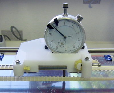
The best way to level the bed relative to the nozzle is to use a dial gauge mounted in place of the extruder using this clamp. If you don't have a dial gauge you can roll a spare piece of smooth rod or slide some film under the nozzle and feel when it is just touching.
The two pillars at the back of the bed have a washer under them to ensure the front can be made both higher or lower than the back. Those pillars are tightened and not adjusted. Front - back adjustment is achieved by adjusting the two pillars at the front. Left - right adjustment is done by turning the Z lead screws. Ideally there would be only one mounting point at the front as only three points are needed to mount a stiff sheet like glass. Having four makes the adjustment more tedious as they tend to bend the sheet and interact with each other.
Start by sliding a washer under the front pillars to set them to the same height as the back. Move the gauge or nozzle to the middle of the back of the bed. Note that level on the gauge, or nudge the Z axis to just touch your feeler. This is the level that we want the whole bed to be at.
Move to the back left corner and adjust the left lead screw to get the same level as the middle. Move to back right and adjust the back right lead screw. Moving the gauge all the way across the back should now read the same height.
Now move to each of the front corners in turn and turn the pillar until the height is correct. Lock them in place by tightening the top screws through the bed.
The whole bed should now be level but usually you need to repeat the procedure a few times due to the interaction of the four points.
Z Home Point
If using a top Z limit switch you set the height of the machine in the firmware and thereby define "0" as "touching the bed" without having to actually crash the nozzle into the bed. Once the bed is levelled, and you have the steps per mm set right, then you home Z and then nudge it down to near the bed. When you can just roll an 8mm smooth rod (for example) under it with no resistance, take the Z value with M114. Subtract 8mm from that and subtract the result from the Z_MAX_POS in the firmware.
For example, if it thinks it is at 7 when it is actually 8 then Z_MAX_POS is too small by 1mm.
Update the firmware and download it. The position should then be accurate when the machine is cold. To get it spot start printing an object and stop it after it has done the outline. Cool the outline and measure its thickness in a few places and take the average. If it is say 0.32mm but the object was sliced with 0.3mm layers then it is too high by 0.02mm so increase the Z_MAX_POS by that amount.
When the Z home point has been set rotate the two Z screw pointers so that they point directly at the Z bars. One can now see if the lead screws get out of sync.
Thermistor Calibration
For best results thermistors should be individually calibrated for two reasons. Firstly they are usually only 5% or 10% tolerance components. 10% at 240C has a significant effect on the plastic. The datasheet value of beta is for a subset of the temperature range because it isn't actually a constant (the two parameter equation is only an approximation).
The second reason is that the bed thermistor is underneath the bed but we are interested in the temperature of the top surface. The extruder thermistor is in the heater block but we are interested in the temperature inside the barrel because that is where the plastic spends most of its time. Plastic has a high specific heat capacity and low thermal conductivity so it is likely to leave the nozzle at a similar temperature.
TBC
Hot End Calibration
Marlin has the ability to do a much better job of maintaining a stable hot end temperature by knowing the thermal properties of the hot end - a system known as PID. If you are using a hot end for which the values are not available in the firmware, the "M303" command will heat and cool your hot end several times and then tell you what the magic Kp, Ki and Kd values are so you can put them in the configuration file.
Extruder Calibration
The E steps per mm should be adjusted so that when commanded to extrude 100mm it actually feeds 100mm. This is done by placing a mark on the filament 120mm above the extruder and telling it to feed 100mm. Then measure the distance to the mark to work out how much it actually extruded. It depends on the diameter of the bolt hobbing and how far the plastic is pressed into it, i.e. how soft it is and the spring tension. Harder plastics will feed faster.
You also need to make sure the slicer knows what volume of plastic it actually gets for a 1mm increment, and that depends on the diameter of your filament - which, sadly, can vary by up to +/- 3%. Measure the diameter using a digital micrometer (available from Amazon for a tenner, and very useful) and then input that figure into the slicing software.
