OptoEndstop 2.1/nl
This page describes something which is no longer the most recent version. For the replacement version see: "Official" Electronics
|
English • العربية • български • català • čeština • Deutsch • Ελληνικά • español • فارسی • français • hrvatski • magyar • italiano • română • 日本語 • 한국어 • lietuvių • Nederlands • norsk • polski • português • русский • Türkçe • українська • 中文(中国大陆) • 中文(台灣) • עברית • azərbaycanca • |
Contents
Overzicht
RepRap's Cartesiaanse assen hebben allemaal een referentiepunt (ook bekend als 'thuis positie' of 'eind-stop) nodig om een referentie te hebben voor bewegingen. Bij het starten van een productierun moet elke as naar zijn referentiepunt teruggaan. Voor de RepRap, gebruiken we een optische schakelaar om het referentiepunt te bepalen. De optische schakelaar helpen ook voorkomen dat de machine bewegingen buiten de gewenste range maken en op die manier zichzelf beschadigen.
3* (drie) optische schakelaar heb je nodig voor een basis RepRap, en *6 (zes) voor een volledige RepRap met zowel begin- en eind- stops.
Voor diegenen die de ZD1901 opto interrupter gebruiken (meestal het zuidelijk halfrond) is een simpel stripboard assembly benodigd. Details zijn hier te vinden.
- You'll need a soldering toolkit to do most of this.
- Read our Electronics Fabrication Guide if you're new.
Hoe te verkrijgen!
Volledige Bouwpakketten
- Volledige bouwpakketten (onderdelen + printplaat) verkrijgbaar o.a. van MakerBot Industries
- Opto Endstop RRS-OE Set x3 van RepRapSource
- Koop het bord van de Duitse RepRap Foundation
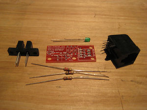
'Ruwe' Componenten
Files
Je kunt de files van de elektronisch downloaden van Sourceforge.
Deze file bevat het volgende:
- GERBER files voor fabriceren van de eind stop.
- PDF files van het schema, koper layers, en silkscreen
- Eagle source files voor modificaties
- 3D rendered image zowel a.s POVRay scene file
- exerciser code om je bordje te testen.
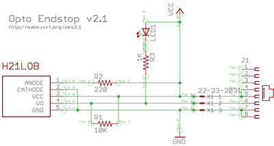
Elektronisch Schema
Interface
Debug LED
De 'debug' Light Emmitting Diode (LED) is een visuele indicator van de status van de schakelaar. Merk op: vanwege beperkingen in het elekrische schema is de LED status geinverteerd met de werkelijke signaal. Dit betekend dat als de output high is, de LED uit is en wanneer de output laag is, is de LED aan. Zie onderstaande tabel voor meer informatie.
Output
De output van de schakelaar is een binaire waarde (1 of 0) dat de status van de schakelaar aangeeft.
 LOW = 0v/GND and HOOG = 5V.  De output van het circuit is afhankelijk van het model van de optische schakelaar.
RepRap is recentelijk overgeschakeld van de  H21LOI naar de H21LOB omdat deze laatste makkelijker verkrijgbaar is.
De H21LOI en de H21LOB zijn identiek, behalf dat hun outputs ten opzichte van elkaar ge-inverteerd zijn. Dit maakt een verandering in de firmware noodzakelijk om de juiste input juist te kunnen interpreteren. In onderstaande waarheidstabel staat beschreven welke waarden er mogelijk zijn van het elektrische schema
H21LOB Waarbheidstabel
| Status | Output | LED |
| Open | HOOG | Uit |
| Gesloten | LAAG | Aan |
H21LOI Truth Table
| Status | Output | LED |
| Open | LAAG | Aan |
| Gesloten | HOOG | Uit |
Fysieke Connector
De v2.x serie van Opto Eindstops is een experiment met het standaardiseren van de connectors. Een van de grote problemen met het oudere v1.0 ontwerp is dat het van de eindgebruiker verlangde een eigen connector oplossing te verzinnen. Wat veel gedoe kan opleveren. Het nieuwe v2.x ontwerp heeft 2 verschillende connector footprints: het oude .100" connector en een RJ45 aansluiting. Het is aan de eindgebruiker welke connector gebruikt gaat worden.
RJ45 Connector
Zeg het na:
Het opto endstop v2.x ontwerp ondersteunt geen ethernet!
Het opto endstop v2.x ontwerp ondersteunt geen ethernet!
Het opto endstop v2.x ontwerp ondersteunt geen ethernet!
What we are doing is hijacking a common and very cheap connector for our own purposes. RJ45 patch cables and jacks are ubiquitous, versatile, robust, and cheap. We've considered and rejected many other connector technologies (RJ11, 3.5mm audio cables, etc) but in the end, RJ45 is the best for our needs. If you have another source of high quality premade cables (that we have not already rejected) please bring it to our attention in the forums (see General FAQ#wires and connectors). Please do not complain about being forced to use these cables, as there is a simple on-board alternative (see below).
Below you will find a pin out table containing the pin-out information on a standard RJ45 patch cable.
| Pin | Color | Function |
| 4 and 5 | Blue and Blue/White | 5V supply |
| 6 | Green | Signal |
| 7 and 8 | Brown and Brown/White | Ground |
.100" Spaced Header
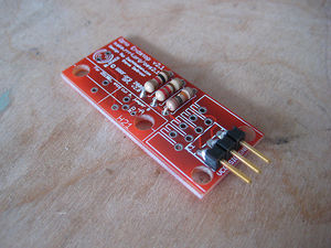
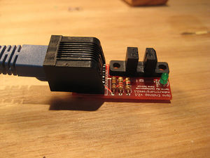
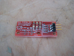
In order to maintain backwards compatibility, as well as giving the user the freedom to chose their desired connector technology, we have included a standard, .100" pitch connector footprint that you may populate as desired. The pins are clearly labeled, and you may wire it however you like. You can solder wires directly to the board, solder in right-angle headers, normal headers, or any other number of technologies. Its up to you as a user to decide. Shown here is an example of using a right-angle .100" spaced header.
Opbouwen
Printplaat Bugs (aangegeven per versie)
- Tot nu toe geen bugs. Meld het als je er een viand op forums.
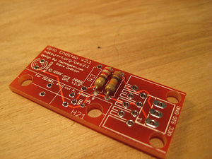
Printplaat
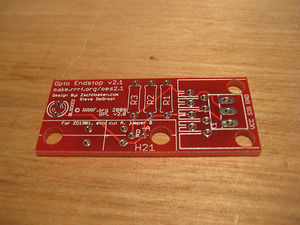
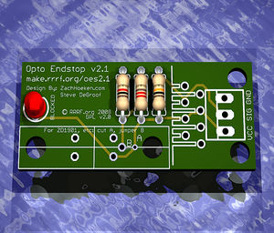
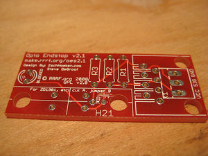
You can either buy this PCB from the RepRap Research Foundation, or you can make your own. The image above shows the professionally manufactured PCB ready for soldering. Its also cheap, only $0.75 USD.
Components
<iframe src="http://www.thingiverse.com/thing:940/partlist" width="500" height="500" frameborder="0"></iframe>
Soldeer Instructies
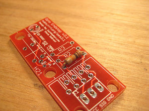
R1 - 10K ohm (Bruin - Zwart - Oranje)
Plaats de weerstand in willekeurige righting. Dubbel check the kleur bandjes op de weerstanden.
R2 - 220 ohm (Rood - Rood - Bruin)
Plaats de weerstand in willekeurige righting. Dubbel check the kleur bandjes op de weerstanden.
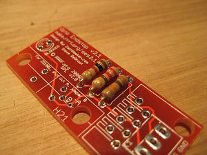
R3 - 1K ohm (Bruin - Zwart - Rood)
Plaats de weerstand in willekeurige righting. Dubbel check the kleur bandjes op de weerstanden.
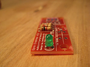
Blocked/Debug LED
Het LED-je moet op de juiste manier worden ingestoken. Steek het korte pootje (min) in het gaatje dichtbij de geprinte tekst en het lange pootje (plus) in het gaatje dicht bij de opto schakelaar.
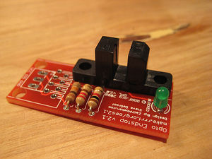
H21LOB
Dit is de optische schakelaar. Het kan maar op een manier worsen ingestoken. Steek het onderdeel op zijn plaats en soldeer het vast.
Power and signal Connector
There are many different types of alternative connectors you could use: You could solder wires directly to the board. You could solder .100" spaced pin headers (both straight and 90 degree), you could solder in a keyed header, or you could solder in female headers. Its all up to you. Shown here is a board with right angle pin headers soldered in. This (or, better, with a straight connector) is how it should be wired for RepRap.
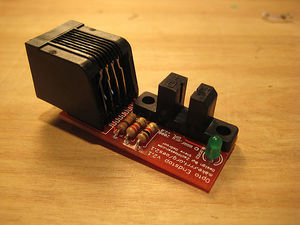
RJ45 Jack
THIS BOARD DOES NOT SUPPORT ETHERNET! This is the MakerBot configuration. We are using the jack to provide simple, easy, cheap connectors.
Insert the jack (it should snap into place) and solder it into place.
ZD1901 Opto Switch
The board also supports using simpler opto isolators that may be more prevalent in your area (say New Zealand). One such opto switch is the ZD1901 opto switch. This is a 4-pin opto switch and it is relatively easy to hook up. There are actually instructions on the board which we'll illustrate below:
Step 1: Cut trace marked 'A'
Cut this trace with an exacto knife, dremel, or other suitable sharp instrument. Take care not to hurt yourself or any of the other traces.
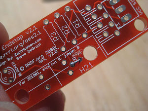
Step 2: Jumper holes marked 'B'
In order to get the signal properly routed, take a small piece of wire and solder it in place as shown to connect the two holes together. You may wish to put the link on the other side of the board to let the ZD1901 sit flush on the board's surface.
Step 3: Solder ZD1901 in place
Solder the ZD1901 in place making sure to insert it in the proper orientation.
Testen!
Als je een RepRap bouwt, zie hier voor de opto-switch test procedure.
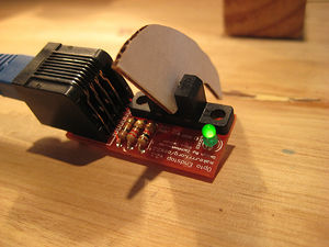
Testen dat de Opto Switch werkt is gemakkelijk: als het printje is opgebouwd blokeer en deblokeer je de opto switch. Het LED-je geeft de status aan van de schakelaar. Daarna kun je het aansluiten op een Arduino of Sanguino om te zien of het signaal goed wordt doorgegeven.
Bedrading aansluiting
There are a few ways to go about this, mainly determined by what set of electronics you have.
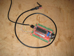
If you are using the RJ45 jack / ethernet cable solution:
If you have one of the new Stepper Motor Drivers (v1.2+, v2.0+) that has an integrated RJ45 jack, then you can simply plug the Opto Endstop to the Stepper Motor Driver, and make sure the Stepper Motor Driver is wired to your Arduino and/or Sanguino. If you do this, make sure that you change the pin definition to the appropriate pin for testing.
If you have an older driver, or want to test it manually, then the easiest way is to cut the end off an old ethernet cable, and connect the exposed wires directly to an Arduino / Sanguino directly. Remember to keep a plug on one end, so you have something to plug into the opto endstop. The advantage of this is that you can use the same cannibalized cable to test all of your opto endstops, as well as all of your temperature sensors. If you're using a standard patch cable, then the wire colors should correspond to the table below:
| Color | Pin |
| Brown | GND |
| Brown/White | GND |
| Green | Signal |
| Blue | VCC |
| Blue/White | VCC |
Note that Brown/White-striped-Brown as well as Blue/White-striped-Blue are both connected to each other. You can use either of them, or solder them together. Your call.
Please note also, that the colors listed above are for an Ethernet cable wired to the EIA/TIA 568B standard, which is commonly seen in patch cables. You may also find a cable wired as per EIA/TIA 568A, which is electrically equivalent, but the green and orange pairs are reversed. In that case you'd use the Orange wire for the endstop signal. You can usually see which colors go to which pins by looking through the clear plastic of the RJ45 connector, and you can easily find many references online for the two wiring schemes.
If you are using the .100" spaced headers:
Its up to you! Make sure you know which wires are what, and that you wire the signal wire to the appropriate
Wire it!
Now that you know what wires to use, wire them to the appropriate places:
| Pin | Arduino/Sanguino Pin |
| VCC | 5v |
| Signal | Digital 2 |
| GND | Ground |
Upload sketch!
Here is a sketch to upload to your Arduino or Sanguino that will allow you to test your opto endstop. Make sure you set it to use the right pin, and optionally the right chip if you're using a non-standard board.
//what pin are we using?
#define ENDSTOP_PIN 2

//which opto enstop are we using?
//this is for the H21LOB
#define INVERTED 1
//this is for the H21LOI
//#define INVERTED 0

void setup()
{
   pinMode(ENDSTOP_PIN, INPUT);

   Serial.begin(9600);
   Serial.println("Starting opto endstop exerciser.");
}

void loop()
{
   if (digitalRead(ENDSTOP_PIN))
   {
     if (INVERTED)
       Serial.println("open.");
     else
       Serial.println("blocked.");
   }
   else
   {
     if (INVERTED)
       Serial.println("blocked.");
     else
       Serial.println("open.");
   }

   delay(500);
}
Gebruiken!
Dit bordje is simpel toe te passen: sluit het aan op je stappenmotor driver, of verbind het direct met je Arduino of Sanguino. Als je het bord gaat aansluiten in je RepRap zorg dat je het aansluit op de daarvoor bestemde pin aansluiting.
Succes!
Historie
Veranderlog
- debug LED toegevoegd.
- support for ZD1901 opt schakelaars toegevoegd
- RJ45 aansluiting toegevoegd
- better labeling van de .100" spacers
- geconverteerd naar een op egale gebaseerd ontwerp (software programma)
Eerdere Versies
- A bugfix on the Opto Endstop v2.0 (not documented)
- Which was an incremental improvement of the Opto Endstop v1.0