PCBScriber
Contents
Overview
PCB Scriber is a RepRap variant that replaces the extruder with a carbide scriber and a through-hole drill, for producing printed circuit boards using the "scratch n' etch" method.
A RepRap equipped with a PCB Scriber is itself, arguably, a RepRap, in that it can produce parts for another RepRap, such as the PCBs for endstops and a RAMPS-style shield.
Hardware
The stls for the printable parts are available here.
Scriber/Drill Holder
The scriber/dremel holder was designed to be compatible with the x-carriage of a 3DPrintMi RepRap, which follows the Vertical X Axis Standard.
Scriber
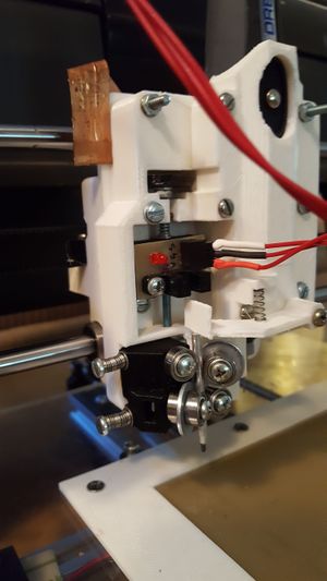
Controlling the pressure used with a scriber is key to scratching hard enough to remove the layout paint, but not too hard. Rather than using a pressure sensor, PCB Scriber uses a machanism with an optical endstop. The scriber pushes an endstop flag up, against the resistance of a spring. The amount of pressure is determined by the position of the endstop carriage, which is adjusted manually.
The carbide scriber tip is removed from the commonly-available General Tools scriber. the scriber is mounted between 6 623 bearings, forming a clamp that allows the scriber to move up and down. The springs used for the endstop flag, the endstop carriage, and the clamp, were taken from retractable ball-point pens. (The springs for the clamp are a bit larger than the others in the setup pictured here.)
Through-hole Drill
A Dremel drill with a Dremel Rotary Flex Shaft (Model # 225-01) is used to drill through-holes. The flex shaft reduces the weight of the x-carriage, and allows the Dremel to be detached and used for other purposes. The flex shaft, with it's drill bit, can be left in place while using the carbide scriber to scratch a board. The scriber can be easily removed out the bottom of the clamp in order to use the drill.
The drill is turned on of off using a Powerswitch Tail, controlled by a digital pin on the Arduino.
Y Carriage Stabilizers
Since we pressing down onto the bed, this modification to the 3DPrintMi design was needed. They require an additional 4 623 bearings. Their height can be adjusted by sliding layers of paper or cardstock underneath them, until the ideal height is found.Origin Corner
The origin corner is designed to hold copperclad board down, on top of another layer of sacrificial board, so the drill doesn't damage the y stage.
X Axis Modification
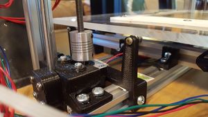
The 3DPrintMi's x axis rests on top of two nuts that are raised and lowered by the 2 z motors. For pressing down, this presents a problem. The entire x axis could just lift off of those nuts. For the setup pictured, clamps were made for the x carriage and the x idler, so that the z nuts were held from the bottom and top. (One clamp also doubles as an endstop mount.) Since these parts include several other non-standard modifications (smaller motor, smaller z-axis rods), they aren't included in the distribution of the PCB Scriber parts.
Electronics
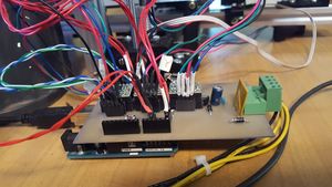
PCB Scriber uses an Arduino Uno running the experimental branch of the Teacup firmware. The scriber documented here uses an AUPS (Arduino UNO Polulo Shield), a simplified RAMPs-style shield (which can be produced by another PCBScriber).
The Z axis is inverted. The minimum Z endstop is positioned on top, so that "home" is when the scriber is lifted. The endstop on the scriber acts as a maximum Z endstop, from the perspective of the firmware.
Endstop
The endstops, including the axis minimums and the scriber endstop, are optical endstop PCBs that can be produced with the PCBScriber itself. The KiCad files are available here.
Firmware
Teacup's experimental branch is available here. As of this writing, the homing order feature, needed for the PCB Scriber, is included in the experimental branch, but not the main branch.
The Z axis is inverted. The minimum Z endstop is positioned on top, so that "home" is when the scriber is lifted. The endstop on the scriber acts as a maximum Z endstop, from the perspective of the firmware. To begin a scratch, the scriber moves down until that endstop is hit.
Use the home order options to make sure the scriber is always lifted first.
G-Code
No support for new G-Code commands is needed. Moving the scriber down, or up, is achieved through homing commands, with only minor changes to the firmware.
Generating the G-Code
A [Processing sketch] was written to generate the G-Code. It takes as input an svg exported from KiCad, and scratches around each copper area on the board several times. It outputs gcode both for scratching and drilling as two separate files. It can also output the paths of the scratches as an svg for review.


