RepRapPro Huxley z axis assembly
|
English • العربية • български • català • čeština • Deutsch • Ελληνικά • español • فارسی • français • hrvatski • magyar • italiano • română • 日本語 • 한국어 • lietuvių • Nederlands • norsk • polski • português • русский • Türkçe • українська • 中文(中国大陆) • 中文(台灣) • עברית • azərbaycanca • |
Introduction | Frame assembly | Y axis assembly | X axis assembly | Z axis assembly | Heated bed assembly | Extruder drive assembly | Hot end assembly | Wiring | Commissioning | Printing | Maintenance | Troubleshooting | Improvements
| A notice about these instructions! |
|
These instructions are open to editing by everyone and anyone. |
Contents
Goal
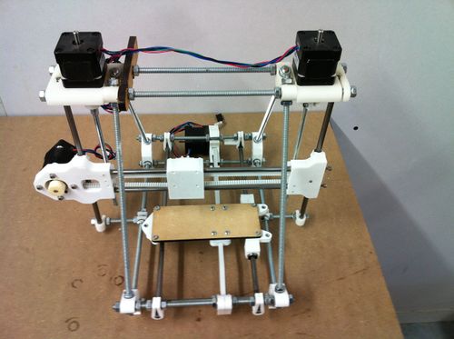
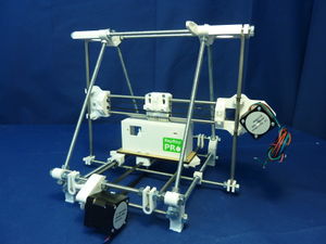
By the end of this stage, your machine will look like this:
Tools
You will need the following tools
- Knife
- Phillips screwdriver
- Digital callipers
Before starting the Z axis assembly
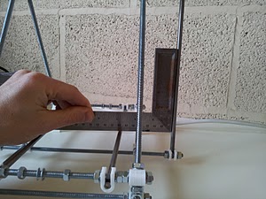
Now is a good time to double-check that the Z smooth rods are square to the Y axis smooth rods. Place a set-square on the Y axis smooth rods and adjust the bar clamps at the bottom of each Z smooth bar in turn to get it square. On machine #248, the distance from the Z-axis bottom threaded rod clamp surface to the Y-axis motor mount corner block was 91.6 mm; this will get you close to square if your machine has the specified corner block to corner block dimensions. Side to side the gap between the Z-axis rod clamp surface and the Z-axis bottom threaded rod clamp was 38.9 mm.
Z axis assembly
Fitting the X axis
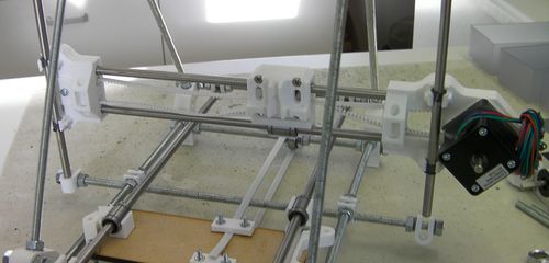
Now undo the U-clips that hold the bottom of the Z-axis rods. Only undo the outside nuts - the inside ones need to stay positioned to relocate the rods when you do things up again.
Undo the M6 nuts that retain to tops of the rods and slide the rods upwards so they are sticking out the top by about 100 mm.
Disconnect one end of the X belt from the X carriage. This will allow you to pull the two ends of the X carriage apart freely.
Push the Z-axis rods down through the Igus bearings in the ends of the X carriage.
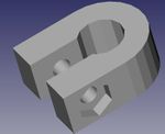
Put one Z rod back in its retaining bottom U clip:
The above picture is from the back of the machine (where the Y motor is).
You will almost certainly find that the ends of the X carriage are not quite the right distance apart. Slide them back and forth on the X rods until everything fits, then put the other Z rod back in its U clip.
Slide the X axis to the top of its travel, and get the gaps between its ends right there. (This will be a distance that cannot be adjusted.) Gently tighten the two screws projecting from the X-axis idler end until they touch the ends of their rods. Don't over-tighten them, as that will bend the Z rods.
Now slide the X axis back down again, checking that it moves completely smoothly. It may bind for two reasons:
- It is tilted (like trying to put a drawer in a chest-of-drawers at a slight angle). This doesn't matter - simply get things straight and try again.
- The gap at the bottom of the Z rods is not quite the same as that at the top. This does matter, and needs to be fixed:
To get the bottom Z-rod gap right, carefully move the U clips by undoing and doing up the nuts either side of them. Do this symmetrically. That is to say, if you move the inner nut on the right three-quarters of a turn inwards, do exactly the same with the corresponding nut on the left. It helps to mark one flat on the nuts with a felt-tipped pen so you can keep track of turns.
Keep sliding the X axis up and down the rods, and make small symmetrical adjustments as above until it runs completely smoothly.
Re-fit the X belt. Pull it tight, then slot it in one notch looser.
Slacken the screws on the X motor, slide them in their slots to take up the slack on the X belt, and re-tighten them.
Fitting the Z drive
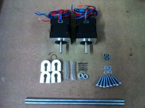
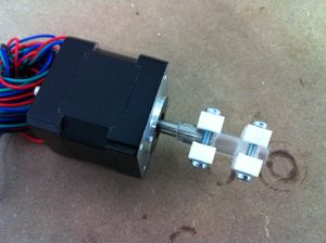
Begin by sliding a length of poly tubing onto each stepper motor shaft with a flat on it.
Next put the couplings together as show below:
Put the couplings and motors to one side for use in a minute.
Place an object on the Y bars to hold the X axis about half-way up its travel:
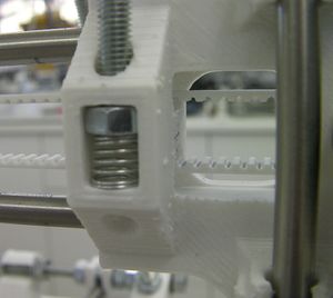
Insert an M5 nuts into its slot in an end of the X axis. Put an M5 threaded rod on top of it and screw it in a couple of turns. Use the rod to hold the nut at the top of the slot and push an anti-backlash spring in under the nut:
Screw the M5 rod down through the nut and spring until its top is about 30mm below the Z-motor brackets at the top of the machine.
Repeat this for the other end of the X axis.
Put the Z motors with their poly tubes in place on top of their brackets and loosely attach them from underneath with two M3 screws with washers under their heads on the motor's diagonals. Have the Z motor wires pointing towards the middle of the machine.
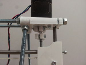
Make sure the screws on the Z couplings are loose. Put the large holes in the couplings over the poly tubes. Move the couplings up till they touch the Z motor brackets, then back them down by two millimetres or so:
Lift the X axis to push the M5 rods into the bottoms of the couplings. Position them so there are about two millimetres clear between the tops of the M5 rods and the bottoms of the motor shafts. You can see this by looking in at gap at the sides of the couplings.
Tighten the couplings.
Tighten the diagonal pairs of screws holding the Z motors.
Measure the gap between the Y rods and the bottom X rod with digital callipers. Turn the Z motors by hand to make the gap each side equal.
