RepRap software tweaking manual
Contents
Tweaking Manual
These pages should be merged such that both pages do not attempt to cover the duplicate topics.
These pages should be merged such that both pages do not attempt to cover the duplicate topics.
This page is under construction.
This is a suggested method to help you get up and running quickly.
Test .stl's are attached at the bottom of this page. - Unfortunately NOT YET. If anyone knows where to find these files...
WideBar.stl is here: http://reprap.org/wiki/File:RepRapSoftwareTweakingManual-WideBar.stl .
Circles.stl is here: http://reprap.org/wiki/File:RepRapSoftwareTweakingManual-Circles.stl .
10mm-cube.stl is here: http://reprap.org/wiki/File:RepRapSoftwareTweakingManual-10mm-cube.stl
Other Apparently Connected Favorite Calibration Objects.
Suggested values, in brackets, are for extruding Capa through a nozzle diameter of 0.4 mm with the 12V GM3 Solarbotics extruder motor run through a 13:38 gearbox .
Warning: You need to open and close an STL file in the software before the preference changes take effect.
Heating the extruder
You will need the extruder exerciser for this section (Tools -> Extruder Exerciser).
- For Capa, 130 °C is a good start.
- Always allow a few minutes after the thermocouple has registered the target temperature before extruding. This ensure that the entire nozzle has acclimatised.
Measure the virgin filament section
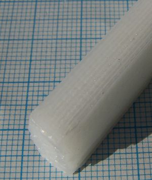
Because of die swell your filament will solidify slightly fatter than the diameter of the nozzle orifice. Knowing the final diameter is important for determining subsequent parameter values.
- Pick a suitable extruder motor speed (210).
- Heat the extruder.
- Extrude a purge section over thin air.
- Cut the filament (by scraping an edge across the orifice) and dispose the purge.
- Collect ~2 cm of clean filament. Any longer and the weight of the filament will start to stretch it and distort the section.
- Allow to cool.
- Using calipers measure the diameter of the filament at the tip closest to where the purge was severed - this end will be least stretched by it's own weight . Be sure not to push too hard with the calipers to ensure fair readings.
- Record the diameter.
GCode:
M83 ; Use relative mode
G1 E20 F200 ; Extrude 20mm of filament at speed of 200 mm/min
Note that this discussion is a measurement of the extruded filament length, rather than the more modern usage of feedstock length from Volumetric_Dimension_settings, or the machine-independent volumetric settings associated with Marlin's M200 Dx.xxx command.
Measure the deposited filament section
When the filament is laid down onto the bed its own weight will distort its profile while it is molten. The nozzle needs to be run over the bed at with a good 2-3 mm clearance to ensure that the nozzle is not squashing the deposited filament . It also needs to run at the correct speed: too fast, and the filament will be under tension, too slow and the filament will be compressed.
- Set the following preferences (File -> Preferences):
- Extruder0_ExtrusionTemp (130)
- Extruder0_ExtrusionSpeed (210) //Speed of the extruder motor
- Extruder0_XYSpeed (247) //Max speed of nozzle in XY plane
- Extruder0_OutlineSpeed (0.17)
- Print the border of the widebar.stl (simply 'Build -> Cancel' during the last border segment).
- Allow to print cool.
- Tip: move the nozzle away using the stepper exerciser and then, while you're measuring up print, you can keep the extruder nozzle hot using the extruder exerciser.
- Measure the border filament section, again with callipers, and compare with the virgin section. If the border section is smaller then the filament is under tension (increase the extruder motor speed, or reduce the nozzle XY speed). Conversely, if the border section is bigger then the filament is under compression (reduce the extruder motor speed, or increase the nozzle XY speed).
- Repeat the print until satisfied (this may take several attempts).
- When you are happy with the parameter ratios, clean the nozzle and then turn the extruder off and allow to cool.
GCode M83 ; Use relative positioning G1 F1000 ; Set the speed G1 X20 E20 ; Move 20mm along X axis while extruding 20mm of filament
Adjust the z=0
Move the nozzle out over the bed. By adjusting the z-flag and homing the bed using the stepper exerciser you can set the datum position for the bed.
The software (at time of writing) prints its first layer at z=0. Using the filament from the previous test adjust the z=0 height so that the filament can freely slide under the nozzle.
Test your setting by printing the widebar.stl border again. Use the callipers to make sure that the nozzle is not deforming the profile of the segment by being too close to the bed.
Setting the curve speed
Due to minor pauses between segments, a piece of code has been added to reduce the impact of filament dumping during pauses. This code comes into play for short segments, and applies to the radii of most profiles. The code speeds the nozzle up during the short segment.
- Set the preference: Extruder0_ShortSpeed (0.8)
- Print the borders of the circles.stl
- Measure the average profile, repeat until satisfied that the average section of the short segments are close to that of the normal segments.
Setting the infill
Now you're confident about your segment sections, it's time to get that into the preferences and checked by printing a :
- Set the preferences:
- Extruder0_ExtrusionInfillWidth (0.55)
- Extruder0_ExtrusionHeight (0.5)
- Extruder0_ExtrusionSize (0.55)
- Extruder0_InfillSpeed (0.17 - initially same as OutlineSpeed)
- Test this out by printing the entire first layer of the widebar.stl
- Adjust preferences until satisfied with the result
Checking layer bonding
Perhaps most important of all is ensuring that your layers are close enough to bond together. But at the same time they must not be too close otherwise deposition will quickly get messy. It is essential therefore that the Extruder0_ExtrusionHeight preference is correct.
- Print the whole of the 10mm-cube.stl
- Adjust the Extruder0_ExtrusionHeight parameter accordingly.
Pay particular attention to the heights of the infill segments compared with the height of the border segments. These should be level. If not, go back to the previous section to adjust your infill settings accordingly.
Troubleshooting
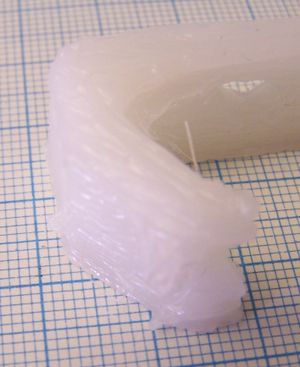
This section gives pictures of the kind of things that can go wrong and what to do about them.
XY speed too fast, extruder too slow, or layer gap too big
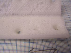
As you can see there are gaps in the infill where it has failed to be laid down properly. This can be caused by:
- The XY carriage moving too fast,
- The extruder extruding too slowly,
- The gap between one layer and the next being too big, or
- The polymer filament jamming in the extruder.
In the first three cases the solution is obvious. The XY speed is set by the following parameters:
- Extruder0_XYSpeed(0..255) The bigger this number, the faster the maximum possible XY speed. There's a detailed explanation here.
- Extruder0_OutlineSpeed(0..1) This is a direct fraction of the fastest possible XY speed above.
- Extruder0_InfillSpeed(0..1) This is a direct fraction of the fastest possible XY speed above.
The extruder speed is set by
- Extruder0_ExtrusionSpeed(0..255) The bigger this number, the faster the extruder extrudes. It controls the PWM signal going to the motor. 255 give continuous 12v; 0 powers the motor off. The effective voltage sent to the motor varies linearly between these extremes. Note that a linear change in voltage does not necessarily imply a linear change in speed.
And the gap between one layer and the next is set by
- Extruder0_ExtrusionHeight(mm) This is the number of mm the Z stage moves down between layers.
In the fourth case, we have found that some polymer filaments are not quite within RepRap filament tolerance specification (which is 3mm +0mm, -0.3mm). In particular occasionally you get a few hundred mm length that can be 3.2 or 3.3 mm in diameter. Such sections jam in the 3mm hole down the PTFE rod that links the extruder to its heated nozzle. There is a simple solution to this problem which sounds drastic, but actually is benign. It is to drill the PTFE out to 3.5 mm (1/8" might just do it, if you have access to Imperial drills, though that's only 3.175mm). The extruder works fine at this diameter. There is no need to do anything with the heated barrel - the polymer is melted all the way down that.
XY speed too slow, extruder too fast, or layer gap too small
This is the exact opposite of all the cases immediately above, except that extruder jamming is obviously irrelevant here.
Got it!
And this porridge was just right...
-- Main.EdSells - 25 Jan 2008


