Smartrap Build Manual
|
English • العربية • български • català • čeština • Deutsch • Ελληνικά • español • فارسی • français • hrvatski • magyar • italiano • română • 日本語 • 한국어 • lietuvių • Nederlands • norsk • polski • português • русский • Türkçe • українська • 中文(中国大陆) • 中文(台灣) • עברית • azərbaycanca • |
Smartrap Mini | How to Get Smartrap | Smartrap Build Manual | How to Use Smartrap | Smartrap Improvements
Welcome to the official document of the Smartrap's assembly.
This is the assembly manual for the Smartrap V 0.4.9 serie. For little changes between versions, we add extra steps.
Each step of building should take around one minute.
Contents
Tools you need:
- Small screwdriver plate for M3
- Bigger screwdriver for M6
- Allen key 1mm
Printed parts
|
plate_base 049 | 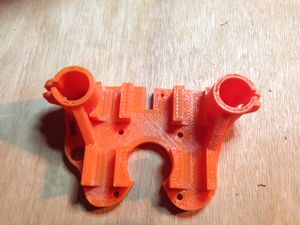
|
plate_x 049 | 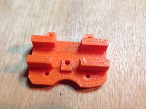
|
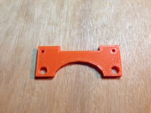
plate_y | ||
|
bottom 049 | 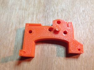
|
endx_huxley | 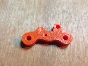
|
endx_back | ||
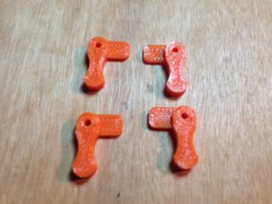
|
glass_holder | 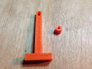
|
glass_support | 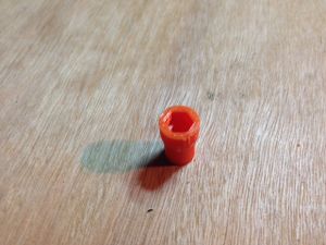
|
z_coupler 049 | ||
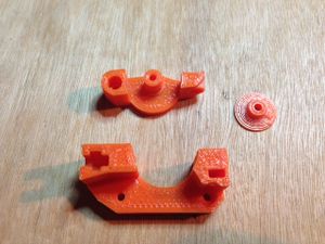
|
direct_drive | 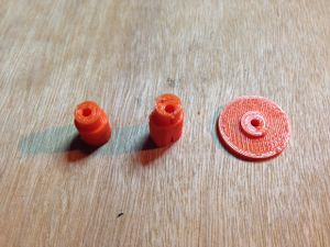
|
belt_axis | 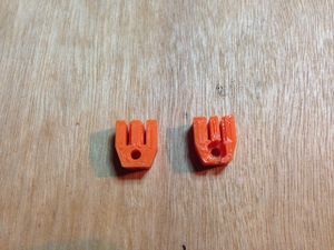
|
belt_tensioner |
Updated parts 0.4.9.2
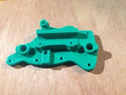
|
plate_base 0492 with integrated bearing support | 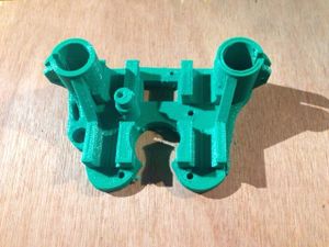
|
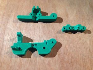
plate_x 0492 with integrated bearing support | |
|
endx jhead lite with arm for mechanical switch | |||
|
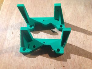
endy with window for gt2 tensioners |
NOTE : - Z coupler is replaced with vinyl tube . Integrated in screws plastic bag
Non printed parts
notes for 0492:
- electronic fan is not shipped anymore. We went back to heaters on pololus.
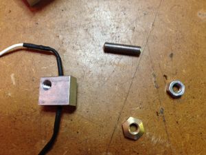
Pre-assemble the Huxley head 049
If you received a jhead lite, please jump this step.
|
1 | 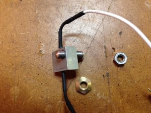
|
2 | 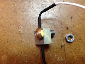
|
3 |
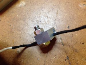
|
4 | 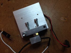
|
5 | 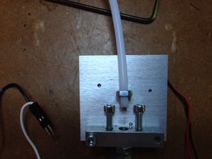
|
6 |
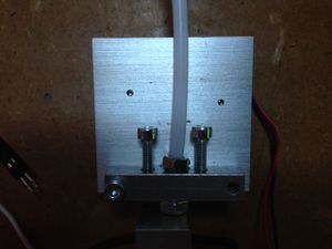
|
7 | 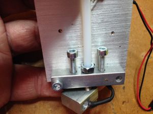
|
8 | 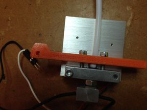
|
9 |
|
10 |
Bottom / base
|
1 | 
|
2 | 
|
3 |
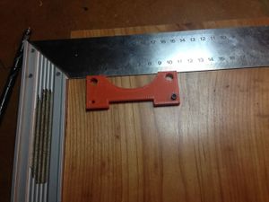
|
4 | 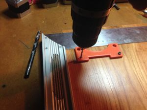
|
5 | 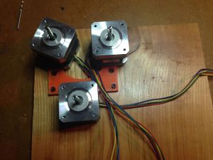
|
6 |
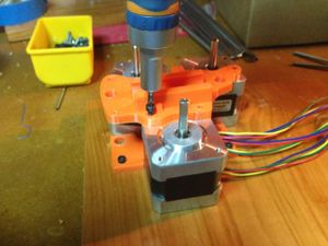
|
7 | 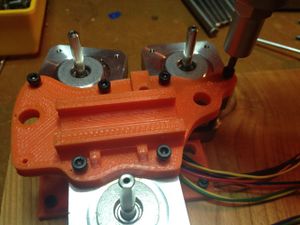
|
8 | 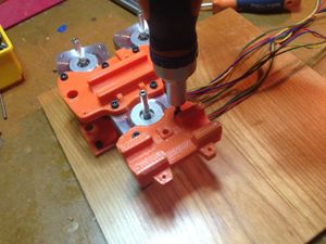
|
9 |
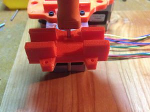
|
10 | 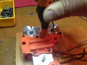
|
11 | 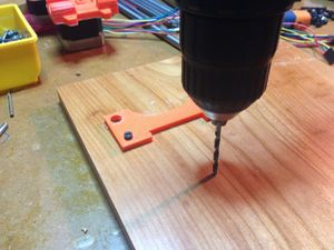
|
12 |
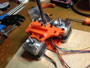
|
13 |
Y axis
NOTE 0.4.9.2 :
- steps 4 and 5 are not necessary anymore. The bearing support is integrated on the plate.
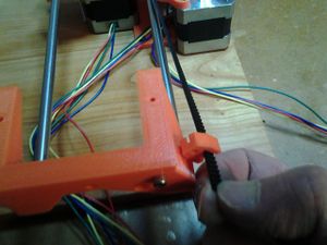
- step 19 : there's no need for screw anymore. Pass the belt in the small window and attach a tensioner. It will be straighten by the other side with the M3x25.
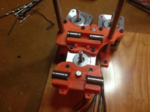
|
1 | 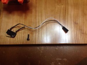
|
2 | 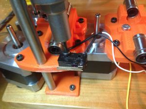
|
3 |
|
4 | 
|
5 | 
|
6 |
|
7 | 
|
8 | 
|
9 |
|
10 | 
|
11 | 
|
12 |
|
13 | 
|
14 | 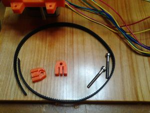
|
15 |
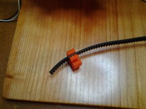
|
16 | 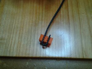
|
17 | 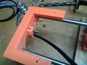
|
18 |
|
19 | 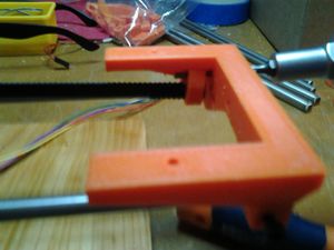
|
20 | 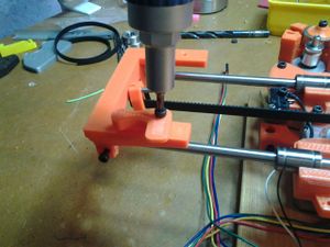
|
21 |
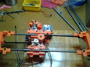
|
22 |
Extruder
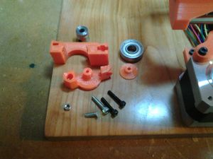
|
1 | 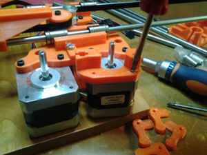
|
2 | 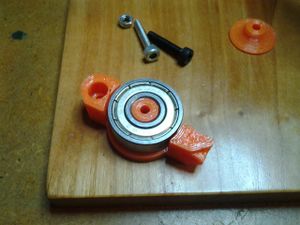
|
3 |
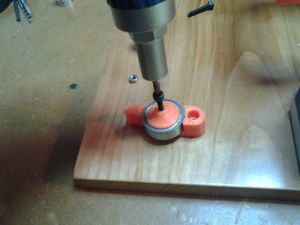
|
4 | 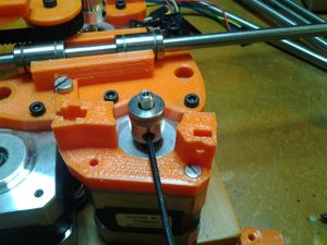
|
5 | 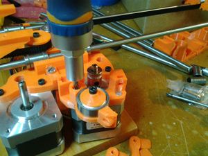
|
6 |
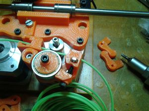
|
7 |
X axis
NOTES 0.4.9.2:
- steps 3 and 4 are not necessary anymore. The bearing support is integrated on the plate.
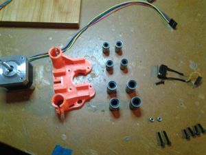
|
1 | 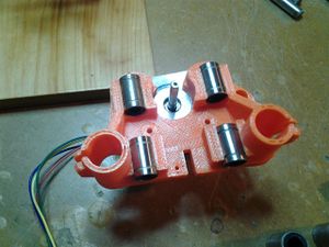
|
2 | 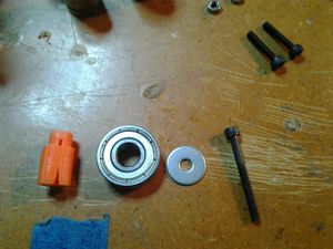
|
3 |
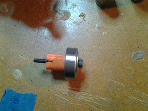
|
4 | 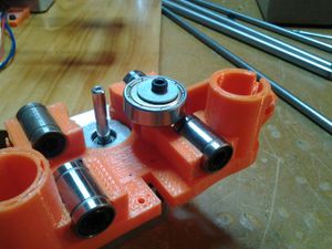
|
5 | 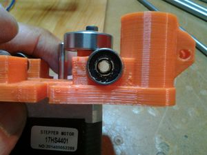
|
6 |
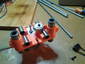
|
7 | 
|
8 | 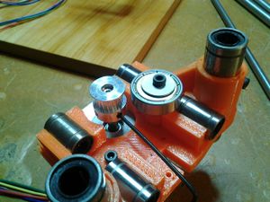
|
9 |
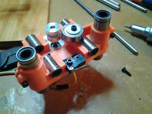
|
10 | 
|
11 | 
|
12 |
|
13 | 
|
14 | 
|
15 |
|
16 |
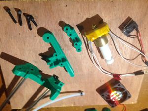
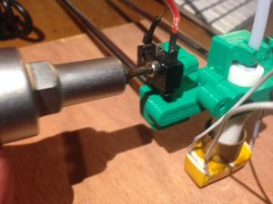
0.4.9.2 : jhead lite assembly
|
1 | 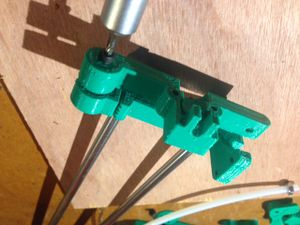
|
2 | 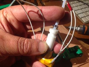
|
3 |
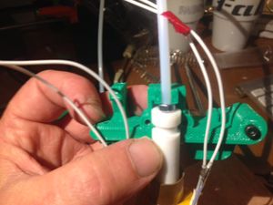
|
4 | 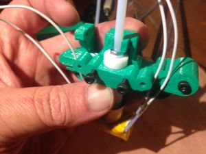
|
5 | 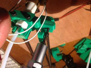
|
6 |
|
7 |
Z axis
NOTE 0.4.9.2 :
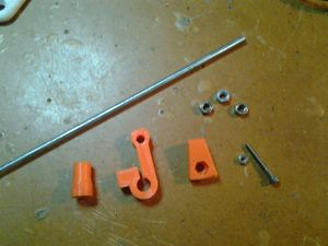
- the zcoupler has been replaced by a 3cm long vinyl tube. There is no need for steps 4 5 6 . Juste insert the tube in the stepper shaft and the M5 thread .
|
1 | 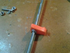
|
2 | 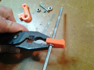
|
3 |
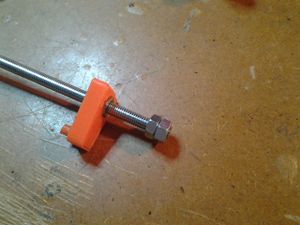
|
4 | 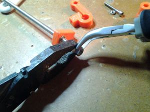
|
5 | 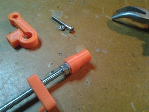
|
6 |
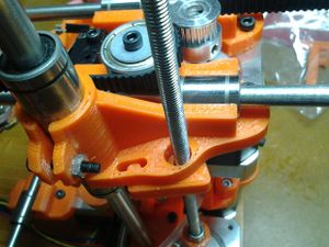
|
7 | 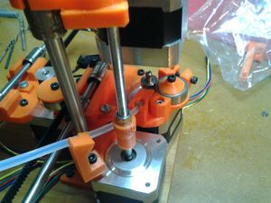
|
8 | 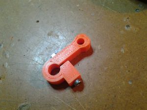
|
9 |
|
10 |
Wiring
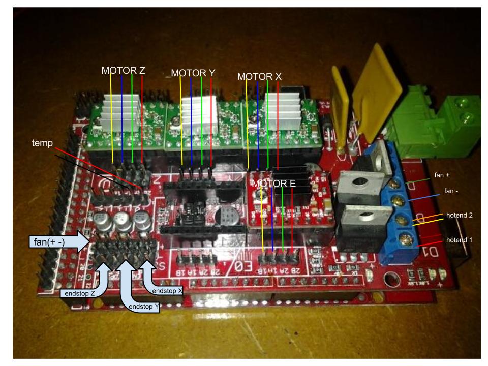
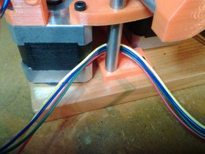
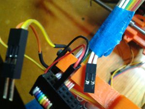
First , here is the electronics card mapping.
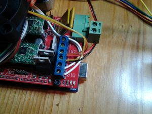
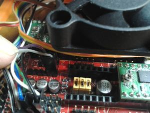
NOTES: if using a huxley , please use the D9 connection for the fan . If using a jhead lite, please use the two first pins of Zmax stop. It is used for +5v and ground. It will then turn to the right speed , always ( no need to control in software).
We use the most standard controler in the reprap world because you can find a lot of documentation about it : look for ramps 1.4 in your search and you will find tons of infos, forum, trics..etc.
|
1 | 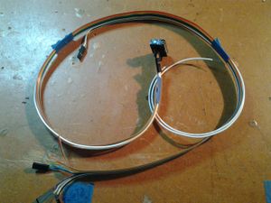
|
2 | 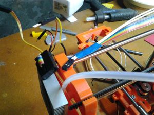
|
3 |
|
4 | 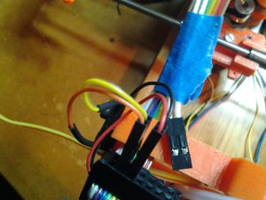
|
5 | 
|
6 |
|
7 | 
|
8 | 
|
9 |
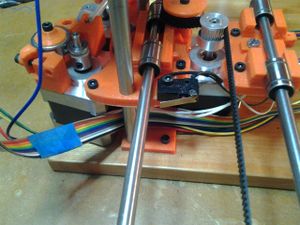
|
10 | 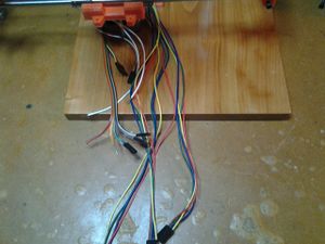
|
11 | 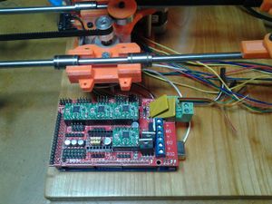
|
12 |
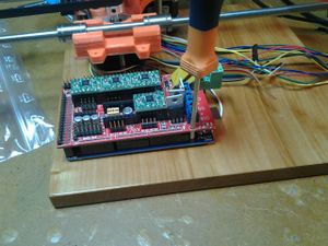
|
13 | 
|
14 | 
|
15 |
|
16 | 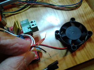
|
17 | 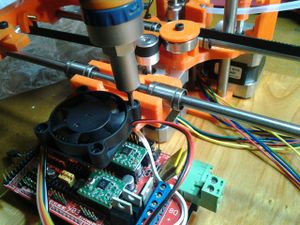
|
18 |
|
19 | 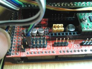
|
20 | 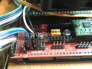
|
21 |
|
22 | 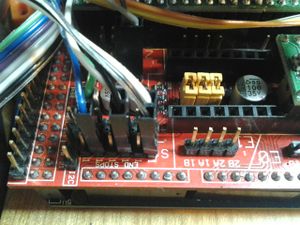
|
23 | 
|
24 |
Finishing
|
1 | 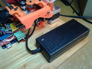
|
2 | 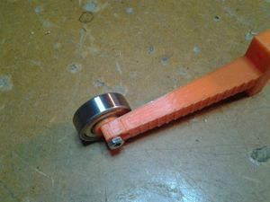
|
3 |
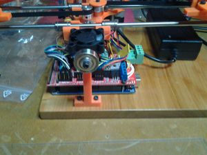
|
4 | 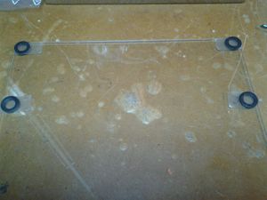
|
5 | 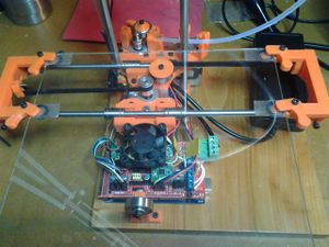
|
6 |
Setup and first print
Now we have our assembly ready, we can start to test and setup the softwares.
Softwares you will need to control and update your Smartrap:
Arduino software : Your electronic card is made of 2 cards. One ( bottom card) is the most standard open source control card , used in thousands of projects : the arduino card ( mega 2560 rev3). It’s a very good idea to download the software and install it on your computer. You will maybe don’t use it immediately , as we pre-installed the firmware , but there’s a big chance you will need it soon. A good side effect is that it installs the good driver on your computer.
Repetier host : Used to Control the printer . This software include another open source project :
slic3r: which is used to slice the 3d models to be ready for printing. Almost all parameters for the Smartrap are adjusted for this software.
Installation
Download and install Arduino software.
Download and install Repetier host.
Download the configuration file from Smartfriendz github repository. ( file : smartrap_slic3r_config.ini )
Initialize
Connect the usb cable between your computer and the Smartrap.
Open Repetier host
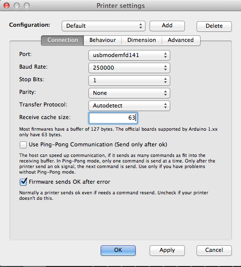
Go to “printer settings” , then select the right port (if not already selected) and choose 250000 for bitrate ( speed communication between computer and printer).
Try to connect clicking the connect button. You should read some feedback in the log panel. The important information to check is the temp. It should indicate the room temp ( 15-25 degrees) and not zero. If you read zero, there is a connection problem on the Smartrap with the thermistor connector.
Plug the power supply.
Go to print panel . Try to move X motor by 1mm and check if it goes to the right direction + 1 X should make the X axis coming to you. +1 Y should make the plate going to the left. +1 Z should make the head going up.
If a motor is going the wrong direction, you can unplug the power , reverse the motor connector on the electronic board and plug back the power.
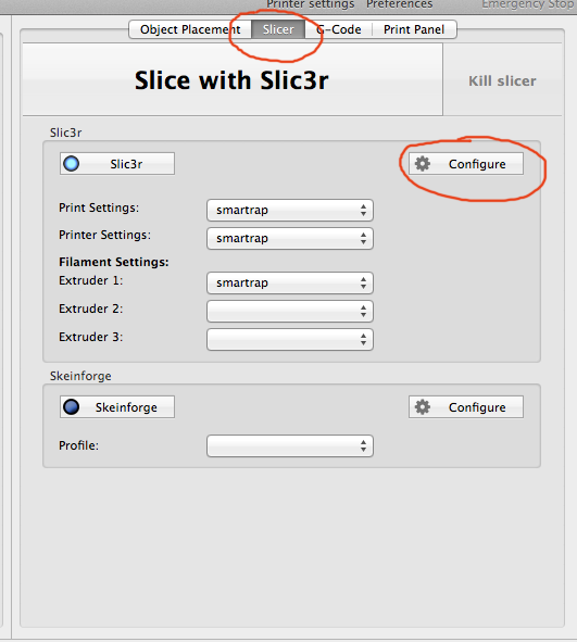
Now , select the “slicer” panel.
click “configure” button in the slic3r part. It should open a new window with the integrated slic3r software .
Select file->Load config , and choose the configuration file you downloaded from smartfriendz. You can close slic3r. It should give you a smartrap selection in repeater host .
If you have problem to load the config file ( could be that there is a new software version and our config file is obsolete) you can see the settings on this page :
http://reprap.org/wiki/Smartrap_Build_Manual_screenshot_repetier_config
Setup head offset with autolevel
The last thing to check and setup before printing is the head placement on the glass plate for the first printing layer. It’s very important because all the part will depend on the qualiy of this layer . It needs to be flat, consistent and well sticking to the glass ( or the part would go away during the print).
The autolevelling system will check the height of the glass ( on the Z axis) on 3 points and will calculate the real plane of the glass, so it will stay at the same distance from the glass at any time.
Unfortunately, as the Smartrap is a kit, every assembly will bring some small differences . One concerning us here is the distance between the plane and the head at the first layer. we need to make a little operation to mesure this distance and give this information to the system . To do that , we will :
Do a home X and Y by clicking on the respective home button for each axis.
Enter a command in the command line . For now, we will test if it does what it should :
G29 (enter)
Now it should up a little, go to first point (20,20) go down until the head touches the bed and activate the Z-stop. It will do three points this way and stop at the third point, head on the glass ! At this point, you can manually move the head up with +Z button. To win time, you can go 1mm , then going by 0.1mm steps until the head is right on top of the glass , counting how much you travelled ( normally, repeater host will show the right value for Z , as we started right after a z-stop that reset the Z value).
This value will be used to tell the Smartrap how height you want the head from the last probe point. To do this you will enter another command :
M555 Z(your value) . The log should tell that you just set a new value for the offset.
Now we need to keep this value after we turned off the power . We will save it to the card with a general command to save all values :
M500.
That’s it. Setup is finished. IF the value is not good, you don’t need to redo all the process. You can simply change the offset value by 0.1 or 0.2 mm : M555 Z1.5 for example.
Now it’s time to test if all is right.
print ! ( at last)
You will download an stl model in repeater host, slice the model and just click the play button. IT should heat the head , then probe the three points, go up a little, go back to point 10.10, then start printing !
