WolfStrap
|
English • العربية • български • català • čeština • Deutsch • Ελληνικά • español • فارسی • français • hrvatski • magyar • italiano • română • 日本語 • 한국어 • lietuvių • Nederlands • norsk • polski • português • русский • Türkçe • українська • 中文(中国大陆) • 中文(台灣) • עברית • azərbaycanca • |
Release status: unknown
| Description | documenting a generic tool/artpiece
|
| License | |
| Author | |
| Contributors | |
| Based-on | |
| Categories | |
| CAD Models | |
| External Link |
Contents
Working Notes
Note: the original German article has instructions on WolfStrap with a toothed belt as well.
Text written in dark magenta has been added by the translator, in order clarify certain aspects of the translation, and is not part of the original German article.
Note: The original German article has been severely expanded. Even if you don't understand the German language you should take a look at the pictures as long as this translation hasn't been updated. --Tiberius 10:50, 24 June 2010 (UTC)
A Google translation of the German page
Files
Google Sketchup 7 File: File:Reprap.skp
Discussion
http://dev.forums.reprap.org/read.php?1,37355
It is difficult to source parts for the Mendel in Germany, so I was looking for a cheap and easy solution to create the parts for myself.
On top of that it should be mentioned that I am by no means a professional woodworker... the important thing being that it worked.
To me Aesthetics is a foreign word, which I have no knowledge about :)
I didn't plan to publicize this, but I was asked to do so...
Comments and suggestions can be made in the German forums.
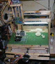
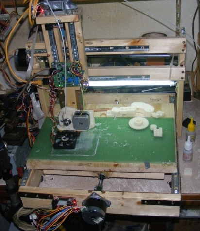
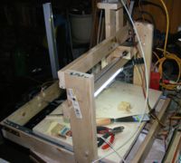
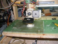
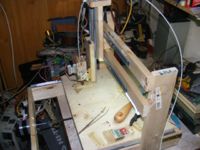
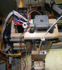
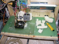
The pictures are from different construction and test phases. This is the end result:
|
|
|
|
| |
|
| Wolfstrap with belt drive: | 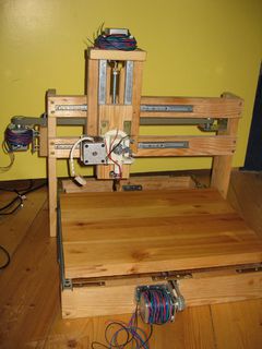
|
In this episode of the EEV blog from sept. 2011, Dave Jones visit the Melbourne Hacker Space (CCHS) and the first demo he's given is a working WolfStrap along with its printed RepRap child.
Extruder
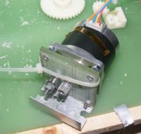
Intially I created the extruder from a block of wood, but I gave up on that idea.Following that, I build this (image to the left) temporary extruder. The heater has been moved to the new extruder. It was mounted with two small wood screws on the aluminum angle at the base of the motor. The cable tie prevented the filament from sliding out.
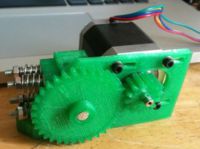
I used this to create the Wade's Geared Nema 17 Extruder .Because my construction was so difficult to control, I had to reduce the extruder speed way down in the firmware, unfortunately the stepper driver had problems driving the motor smoothly at that speed.
The Wade-extruder works great.
Even with a 0.28Nm Stepper.Wiki-Geared_Nema17_Extruder
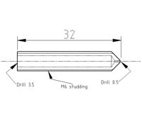
Originally I had planned to make the nozzle in the same manner. I discovered the drawing cannot work this way.
Following a few trials, I performed the following changes:
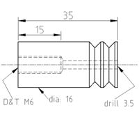
The drilling in the brass part, specified as 3.5mm, I used a 3mm drill. The drills are rarely very precise, so the hole usually ends up approximately 3.1-3.2mm in diameter. I made the the hole in the teflon part, the isolator, using a 2.8mm drill. On top of that, I shortened the part to only 25mm long, in order to keep the length of the hole shorter. Teflon is very slippery and is relatively soft. Once the fillament is in the hole, it slides quite easily despite the small diameter. The brass part is very hot, so the filament adapts to the shape.What do I achieve by this?
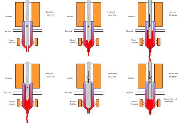
I had the problem that the fillament pushed upwards, out of the nozzle, and as soon as everything was cooled down, the nozzle stopped working. (Animation of a Spoolhead)
This solved that issue.
On top of that, I tighted the end with the brass threading with at hose clamp. This way the part is cooled from the outside and the brass nozzle remains in the teflon part even under pressure. Due to the head, the teflon turns soft, and initially the nozzles were pushed out.
I glued this contraption onto the Wade-extruder using superglue, and it works.
Postscript from http://reprap.org/wiki/WolfStrap translated and added 12/24
With the knowledge and experience which I now gained with various types of extruders, I have to modify the statement, the nozzle 3 or 3.2 mm is relative. The diameter of the nozzle depends on it's length. A long nozzle should be drilled 3.5 mm.
Since the nozzle temperature drops lower toward the top, and cooler filament is harder, then at some (heater temperature dependent) depth in the nozzle the hardness level is reached where the filament is not of a consistency to be dimensionally stable. At this point it presses out to the inner wall of the nozzle and forms a seal.
Bill Of Materials
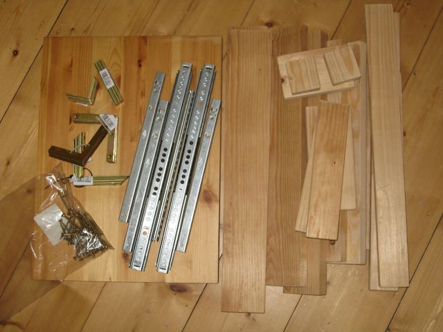
The dimensions given here are for lumber commonly available in Germany. The width and height matches the German building code for laths supporting a roof; the actual dimensions are not terribly important, and can be adapted to dimensions readily available in your area.
Wooden Parts
| Quantity | Description | Type | Comments |
|---|---|---|---|
| 2 | 445x18x45mm | Board | Drawer slides X-axis |
| 2 | 200x18x45mm | Board | Drawer slides Z-axis |
| 1 | 300x18x45mm | Board | Attachment for the captive nut, Y-axis |
| 2 | 50x18x45mm | Board | Attachment for the captive nut, X-axis and Z-axis |
| 2 | 415x18x70mm | Board | Base Frame |
| 2 | 450x18x70mm | Board | Base Frame |
| 2 | 350x18x70mm | Board | Vertical frame, X-axis |
| 1 | 160x18x70mm | Board | Z-axis, extruder mount |
| 1 | 110x18x70mm | Board | Z-axis, motor mount |
| 1 | 300x400x18mm | Board | Bed. A 5 mm plywood may be used to reduce mass. |
Everything is plain softwood. The cheap kind from the hardware store. (It is not intended to be long lasting) Be careful to choose only straight boards and planks. Leave the warped behind. If you intend for the machine to last longer, better quality wood can be used and glued together as well as using screws.
All dimensions are rough measurments, some adaptations will be required.
Non-Wooden Parts
| Quantity | Description | Type | Comments |
|---|---|---|---|
| 2 | 250mm | Rail | Come in pairs. Four total rails. |
| 1 | 450mm | Rail | Come in pairs. Two total rails. |
| - | 4x25mm SPAX screws | Fastener | A good handful of screws (Ex. Spax) |
| - | 3x15mm SPAX screws | Fastener | A good handful of screws |
| - | 4x35mm SPAX screws | Fastener | A good handful of screws |
| 3 | NEMA 17 bipolar stepper motors | Stepper | Be sure to get ones with at least 20mm of shaft length |
| 6 | 100x100mm brace | Fastener | Corner braces for base frame (Ex. Corner Brace) |
| 4 | 120x120mm brace | Fastener | Flat corner braces for base frame |
| Option 1: Threaded Rods | |||
| 2 | M10x350mm | Threaded rod | X-Y-axis |
| 1 | M5x200mm | Threaded rod | Z-axis |
| 4 | M10 nut | Fastener | X-Y-axis. 2 per axis. |
| 2 | M5 nut | Fastener | Z-axis. 2 per axis. |
| 3 | Aquarium tubing | Misc | Coupling purposes |
| 4 | Hose clamp | Misc | Coupling purposes |
| Option 2: Timing Belt | |||
| 1 | 840mm×5mm T5 pitch timing belt | Belt | Y-axis |
| 1 | 900mm×5mm T5 pitch timing belt | Belt | X-axis |
| 1 | M8x18cm | Threaded rod | Z-axis |
| 3 | M8 nut | Fastener | Z-axis |
| 1 | M8 brass plug | Fastener | |
| 1 | Cable tie | Fastener | |
| 4 | 60mm chair angle | Fastener | |
| Optional | |||
| 4 | 608 roller skate / inline skate / skateboard bearing | Bearing | |
The seat angle can be quite easy to convert with holders for 42mm flange NEMA17 steppers (see below) In Mendel timing belt kit is usually included in a Z-strap width 16mm. For one need only one Mendel 5mm wide, after splitting then remains a second.
Building instructions
Tools required: Try square, measuring tape, dremel, Electric screwdriver, drill bits for wood and a circular saw.
It is best to begin with the body for the bed, all connections should be pre-drilled with the Dremel and a 2.5mm drill bit, so the woold does not crack
Y Axis
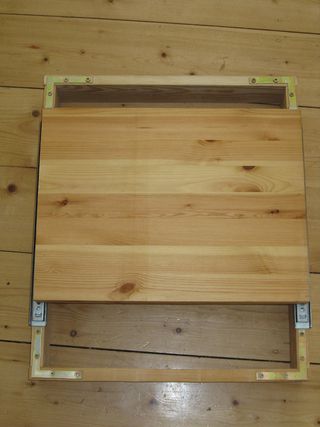
For this we need the 4 wood battens 18x70 (415, 450) mm. Right and left are the two long parts. Using these, make a rectangular frame (like a drawer) as square as possible. The try square is useful for this, along with the angle pieces, and if possible, clamps. Mount the two long drawer slides [centered on the long sides] on top of this frame. See to it that they are parallel [and square], otherwise there will be problems later on.
Now extend the two rails, in order to get at the fastening holes on the slides, and turn the frame over and placing the slides on the wooden board which will later become the printing bed, fasten them to the bed [probably one screw on both at one end, slide for access to the other end and to verify easy movement] and then screw together tightly.
Test whether it slides without resistance back and forth. Great. Great.
Now we draw markings for the motor on the front, drill out the holes and mount the motor. This is a bit easier if we remove the board for the printing bed again.
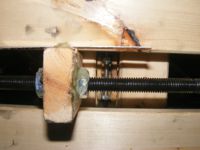
Now it is time for the captive nut. We'll need the 300mm piece 18 x 45mm wood. We mount it lengthwise under the bed, and push the bed up against the axle of the motor, just hard enough to make a tiny indentation in the wood (This way you don't have to do any measuring). Drill a 12mm hole where the indentation was made, so the M10 rod can easily fit. Now everything is starting to shape up :-)
Now you can mount the rod to the motor. This requires a piece of aquarium tubing (20-30mm) and push it over the axle of the motor, then tighten the hose to the axle using a hose clamp. Screw a nut on the rod, push the rod through the 12mm hole and add another nut to the other side of the board.
[edit to note that the nuts are glued to the board in the picture]
Attach the aquarium hose from the motor axle to the rod and tighten the connection using hose clamp. Ensure that it doesn't wobble when the motor is running. The first axis is complete... applause.
X Axis
So now we need the two 18x70x350mm boards and the base frame with the Y-axis. The two boards are positioned in the rear third (approximately 100m from the rear) right and left from the frame. Take great care that the boards are at right angles to the frame and that both the height and distance from the rear is identical, they must be positioned "precisely" opposite each other. You'll need at least 4 screws per board. In order to stabilize the vertical section we'll attach the crossbeams (18x45x445mm). The first should be flush with the upper edge, ensure that the two vertical boards remain parallel, while attaching the beam. The second should be placed at a distance of about 47-48mm, a 18x45mm board should be able to pass through with comfort, and try to keep the two beams as parallel as possible. It is starting to look quite nice.
Drill the holes for the motor on the left side. The middle of the motor axle should be 60mm below the top and flush with the board (The motor axle will then be approx 20mm towards the rear). The motor axle should be as far as possible towards the front, otherwise the fastening for the X axis captive nut will have to be too long (and unstable).
So until now, everything was quite easy...
Now it is time for the Z axis. For this we need the 18x70x160mm board and the two 18x45x200mm boards. We place the smaller board, which will hold the extruder in front of us and screw the drawer gliders with the small U onto it.
[CAUTION: It is better to use the drawer slides the other way around as in the picture. With the closed side to the front subsequent lubrication is difficult .-- Tiberius 10:39, 24 June 2010 (UTC)]
As far as possble towards the outer edges, both should be flush with the short side. This is also the side where the detent of the slide drawer is. It is very VERY important to keep the slides parallel, otherwise the Z axis will jam. You must be able to put the motor between the slides, otherwise the motor will not fit later on. Now the two 200mm boards are attached. The outer distance must be 110mm and the edge of the extruder board, where the slides are flush, should also be flush with the two boards. Now everything can be raised up in the vertical, and both drawer slides point upwards (the detent position is downwards). Measure once again if the two boards change their relative distance when the extruder board is moved back and forth, if so, the drawer slides are not parallel. Everything fine? Then move on.
The Z axis is standing vertical in front of you, facing the two boards... take a drawer slide, put it sideways in front of you, the detent position towards the right. This is how it is attached, with the small U centered at the lower end of the boards. One small screw per board. Now let it rest on the extruder board, and attach the second drawer slide the same way, parallel, with at distance of approx 80mm above it. I placed a small guide between the two in order to get them parallel. Slide everything back and forth, it must not jam. So far so good.
Now everything has to be mounted on the X axis. The best will be to screw both slides on one side first. Not too tight. Now we have to take care, that everything will be parallel to the bed. I used a small support for this. The left hand side first, placing something/anything as support, since the precise height does not matter. Then I pushed it right, drew markings, and screwed on. Later on you will have to place something on top of the board, since the wood is never totally flat, this way minor mistakes can be corrected. I use the green plate for this.
| But... something is still missing... of course, the captive nuts.
Now, having mounted the X-axis, it is possible to mark the position for the captive nut on the right board of the Z-axis. I cut a small block of leftover wood 18x45x70mm. The Z axis has to be removed... unfortunately. Only the board with the two drawer slides, the rest should remain attached. When the small block is attached, push it against the motor axle, in order to make a small indentation where the hole (12mm) will need to be drilled. Remove the small block, drill, now glue should be used when it is reattached (this is a weak point). You should be able to push the X-axis back and forth and the block should move between the two crossbeams. Does it? great. |
Now the threaded rod can be mounted in the same way as with the Y-axis. Don't forget the nuts, one nut on each side of the block.
Now only one board should be leftover. 18x70x110mm where the Z motor will be mounted, in such a way that it is positioned in the middle.
[If you can, use a Forstner drill bit opposite the motor mounting side to allow space for coupling the threaded rod to the shaft of the motor, because the thickness of the board doesn't let the shaft extend very far out on the other side. ]
As you can see, you need to drill two additional holes besides the motor, otherwise the drawer slides will be in the way. I use 20mm holes. You will have to measure the exact position. It depends on where you mounted your drawer slides. But you have made it sofar, so you will be able to handle that.
I ran into some issues with the captive nut holder for the Z axis... I tried to do it once more with a small block of wood. Again a piece of the 18x45x25m which I then slotted. I glued two nuts into the slit and screwed the M5 threaded rod onto the nuts. If I had to do it again, I would have used a small angle bracket, the glued nuts in the slit won't hold for long.
[edit] Modification to the captive nut holder of the Z-axis, I now have a bearing block for the M8 drive. It's just a small block drilled halfway through with a 22mm Forstner bit, and then drilled through with a 10mm bit. It holds a 608 bearing between the drive nuts and is attached from the bottom to the two frame pieces of the Z-axis. - Tiberius 12:37, 24 June 2010 (UTC) [end edit]
My suggestion would be to use a 50x20x15 angle bracket, drill a hole in the short plate for the threaded rod. Then use the same priciple as with the wooden blocks, place a nut on each side of the holes. This is where your ideas will be needed, I cannot chew all you food :-P
If you've come this far: Congratulations, you have held out quite long. Now you are probably asking yourselves, what is the purpose of using two nuts for the blocks... if I tightened both too much, the axle would jam. This way I have neutralized the backlash. First glue one nut with hot glue to the block of wood...now the threaded rod will move the block.
If you turn the motor slowly back and forth you'll notice that the movement is delayed, this is the backlash. Because of this tighten the second nut carefully, just so that the rod can still turn and then glue the nut. If I ignored the backlash, it would later be visible in the printed parts, holes will be ovals, corners wouldn't be corners, etc.So, I hope it wasn't too complicated.. if there is anything you haven't understood, feel free to contact me. I'll rewrite the corresponding paragraphs in order to make everything clearer.
The construction time was two days (without building instructions)
- you may keep any typos you find :-)
--Stoffel15 11:35, 3 March 2010 (UTC)
--translated by anton 15:03, 10 March 2010 (UTC)
Toothed Belt instead of Threaded Rod
 Any one want to copy the Toothed-Belt-WolfStrap docs from the German language WolfStrap page? --Sebastien Bailard 05:39, 24 December 2010 (UTC)
[Edit: did as much update / translation as possible - rumbarg]
Option 1: threaded rods
- Stoffel15 11:35, 3 March 2010 (UTC) First, we draw on the front of the Y-axis frame, the holes for the motor, drill and attach the motor. If you take the motor axis, a Forstner drill bit you have more room around the motor axis for connection to the threaded rod. The whole thing works better if the front bar is remade. Then push the table against the motor shaft so that an impression is formed (then you don't need to measure). At the point we drill a 12mm hole, the axis of the M10 easily fit through. But everything looks good ever :-)
Now you can attach the axle to the motor. You take the piece of aquarium tubing (20-30 mm) and push it over the axle of the motor and tighten with a hose clamp. A nut on the shaft, slide the shaft through the hole in the base, another nut, and fasten the axle to the motor shaft's hose with a hose clamp.
The motor for the Z-drive you have already set out on it's small board between the Z-standing bars. The Z-driver mounts on the threaded rod. Then the rod connects to the motor shaft and also is attached to the extruder to for support so the axis does not wobble excessively when turning.
Option 2: Mendel Z-Strap
In the lead up to my building I had Wolfgang pointed out the speed problems with the screw drive to convert him to have forced himself on ball chains. My goal was to use only parts where possible that can be adopted later in the Mendel. So I have my X and Y drives built since the timing belt needs to be purchased anyway for the Mendel .-- Tiberius 11:38, 21 June 2010 (UTC)
The Z-belt of the Mendel-belt set is just the right length for the Y-axis of the WolfStrap. In the case of the X-axis it's marginal. The length of the X axis must be increased some. Since the Mendel Z-strap is 16mm in width, there must also be in that case 2 belts of 5mm width in the appropriate length. I've decided to use the narrow belt on the Y-axis and the wider for the X-axis, because my Y-runners move more easily.
Belt pulleys are also needed - either printed, or bought. I got mine from the model construction department of Conrad. The teeth need to be 5mm to match the Mendel belts. You also need the wheels for the other end of the axle. This I improvised by using for each a 60 mm L-shaped bracket, a M8x30 bolt, 3 nuts, 2 large washers with 8mm bore and depending on the width of the belt, one or two skateboard bearings. You need only two of the 608 ZZ bearings for the Mendel if you're going to build a Wade's extruder, but the bearings are cheap (eBay: 10 pieces for 6€)
Since the motors are mounted on the axle under the belt drive at a 90 ° angle motor brackets are also required. '60mm seat angle' or 'chair angle' in EU can fulfill that purpose.[nothing like it found yet in the US] The diagonally opposite holes in these parts (Stuhlwinkel 60mm Schenkellänge) have the same distance as the diagonally opposite holes in the casing of a NEMA17 motor. Unfortunately, the large hole in the corner is not in the middle so you cannot put the motor shaft through. You can either drill a hole exactly in the middle of the angle or as I did it enlarge the existing hole towards the center with a Dremel cutting wheel.
The motor mounts can be attached in such a way on the frame that the belt can be tightened and aligned. The 'idler' end and belt should be mounted first, with the belt fed out through an access hole where the motor will be mounted. Assemble M4 screws through the two holes nearest the mounted pulley, add two nuts and a washer. Place the motor mount bracket so that the 4mm screws go into 4mm holes drilled in the mounting location [see x bracket offset mounting block below] and slip the belt onto the pulley. The nut against the bracket should be tightened and the one against the washer can be adjusted for tension. Two wood screws in the bracket holes away from the pulley allow the shaft to be made parallel when the belt is tight.
The X-axis was offset horizontally with a small board required to fit the belt length, a stack of bearings has a wood screw and a few washers screwed in this small board to allow the belt to fit through the hole in the Framework. For narrower pulleys this is probably not necessary. For the Y-axis, it did fit right. The motor is outside of both axles on the frame, the improvised idler pulleys are both inside.
Theses
Finally, the extruder must be mounted to the extruder carrier. That depends on what extruder you use. The Wade-Extruder is easy to fasten with two corners on support boards. Choose a metal angle of the mass of the extruder as close as possible to attach to the boards. It is necessary to drill holes in the angle itself if the existing ones do not fit. The cable holder on the boards are well suited as a guide for the filament. Now your WolfStrap is ready for connection to the electronics. Seek out suitable places to mount the boards on the frame and run the cables.
User Information Lubrication of the rails
The drawer rails are equipped with some strange lubricant. Oil appears to lead to gumming up this stuff. Generally, the lubricant does not tend to stick together, so do not use oil.
