Troubleshooting Reprap Prusa Arduino 2560 + RAMPS 1.4
Posted by jonze
|
Troubleshooting Reprap Prusa Arduino 2560 + RAMPS 1.4 December 27, 2011 04:07PM |
Registered: 12 years ago Posts: 9 |
Hi all,
I am having a bit of a problem with the wiring of the reprap electronics, and I was wondering if anyone could help. Basically, I uploaded the firmware, but the motors do not seem to move at all.
I am building a reprap prusa, and for my electronics I am using the Arduino 2560 board with RAMPS 1.4. I am using the most recent Sprinter firmware and Arduino-0023. I bought the electronics from mixshop.com.
I uploaded the firmware onto the board, no problem. In pronterface, I can change the temperature on the hot end, and the thermistor on the extruder works as well. However, when I try to get the axis motors moving, I find that nothing moves. I re-checked the wiring using the reprapwiki RAMPS 1.4 wiring schematic found on the RAMPS 1.4 wiki page, but it still did not work.
Here are some additional facts:
- Suspicious that something was wrong with my RAMPS board, I uploaded the test firmware found here (http://reprap.org/wiki/File:RAMPS1.4_TestCode.pde) into my Arduino 2560 board (i.e. the board that sits underneath the RAMPS board). The firmware heated the extruder, there was 1 green LED (LED1) and 2 red LEDs (LED3 and LED4) flashing on the RAMPS board, and 1 red LED and 1 green led lit up on the Arduino 2560 board. I'm not sure if these are the only LEDs that are supposed to light up, but since the heating works, the whole board shouldn't be screwed up, should it?
- I swapped out the pololu stepper driver boards on the RAMPS thinking that maybe that was the problem but no change.
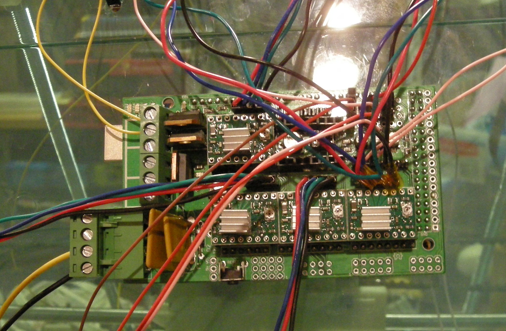
The picture I've attached shows my electronics. Note that the yellow and black wires in the bottom left are from a standard computer power supply. I stripped the ends from a yellow and black wire, and then attached the green wire to another black wire coming out of it.
Any help would be really appreciated, since I really am not sure what's going on.
Thank you.
I am having a bit of a problem with the wiring of the reprap electronics, and I was wondering if anyone could help. Basically, I uploaded the firmware, but the motors do not seem to move at all.
I am building a reprap prusa, and for my electronics I am using the Arduino 2560 board with RAMPS 1.4. I am using the most recent Sprinter firmware and Arduino-0023. I bought the electronics from mixshop.com.
I uploaded the firmware onto the board, no problem. In pronterface, I can change the temperature on the hot end, and the thermistor on the extruder works as well. However, when I try to get the axis motors moving, I find that nothing moves. I re-checked the wiring using the reprapwiki RAMPS 1.4 wiring schematic found on the RAMPS 1.4 wiki page, but it still did not work.
Here are some additional facts:
- Suspicious that something was wrong with my RAMPS board, I uploaded the test firmware found here (http://reprap.org/wiki/File:RAMPS1.4_TestCode.pde) into my Arduino 2560 board (i.e. the board that sits underneath the RAMPS board). The firmware heated the extruder, there was 1 green LED (LED1) and 2 red LEDs (LED3 and LED4) flashing on the RAMPS board, and 1 red LED and 1 green led lit up on the Arduino 2560 board. I'm not sure if these are the only LEDs that are supposed to light up, but since the heating works, the whole board shouldn't be screwed up, should it?
- I swapped out the pololu stepper driver boards on the RAMPS thinking that maybe that was the problem but no change.
The picture I've attached shows my electronics. Note that the yellow and black wires in the bottom left are from a standard computer power supply. I stripped the ends from a yellow and black wire, and then attached the green wire to another black wire coming out of it.
Any help would be really appreciated, since I really am not sure what's going on.
Thank you.
|
Re: Troubleshooting Reprap Prusa Arduino 2560 + RAMPS 1.4 December 27, 2011 04:22PM |
Registered: 13 years ago Posts: 818 |
Hi Jonze,
One obvious observation is that the Single in line headers on the Pololu stepper drivers don't seem to be soldered on the top and I doubt you have managed to solder the reverse side as the connector would have been in the way? tell me they are not just loose on the boards?
Other than that have you adjusted the Pololu current limiting pots, the wipers seem to be in different (random) positions?
Then can you move the extruder motor? if you can but none of the X,Y,Z motors move then check how your end-stops have bee wired, they may be telling the electronics to stop the motors from moving if they are constantly activated (you can change switch/opto orientation in hardware or firmware)
And just as a side issue, you want to have a few more +12V (Yellow) and GND wires going into the Two sets of Power inputs on the board, the other one is for the heated bed, but even the main power should be fed with 2 x yellow and 2 x GND wires from an ATX Supply.
Any of that help?
Cheers,
Rich.
[richrap.blogspot.com]
|
Re: Troubleshooting Reprap Prusa Arduino 2560 + RAMPS 1.4 December 27, 2011 09:55PM |
Registered: 12 years ago Posts: 9 |
Rich,
Thank you for your reply. I appreciate your suggestions and I just took some time to try them out.
> One obvious observation is that the Single in line headers on the Pololu stepper drivers don't seem to be soldered on the top and I doubt you have managed to solder the reverse side as the connector would have been in the way? tell me they are not just loose on the boards?
No, I did not solder them--I just soldered some new pololu stepper drivers to the pins, and plugged them in to the board. There doesn't seem to be any movement of the motors.
> Other than that have you adjusted the Pololu current limiting pots, the wipers seem to be in different (random) positions?
Just to be clear, the pots are the small screws on the right of the stepper driver heat sinks, right? I tried turning them so that the flat end of the circle on the pots faces 3 o'clock, 12 o'clock, and also 9 o'clock. No motor movement.
> Then can you move the extruder motor? if you can but none of the X,Y,Z motors move then check how your end-stops have bee wired, they may be telling the electronics to stop the motors from moving if they are constantly activated (you can change switch/opto orientation in hardware or firmware)
I got a soldered brand-new stepper driver and plugged it in to the extruder motor area. There once again was no movement.
I also doubled up the power supply's yellow and black wires separately as per your suggestion, so thanks for that heads-up.
I will keep on tweaking, but do you think there could be anything else, aside from the fact that the RAMPS is busted somehow? Like the orientation of the stepper drivers?
Thank you again.
Jonze.
|
Re: Troubleshooting Reprap Prusa Arduino 2560 + RAMPS 1.4 December 28, 2011 04:32AM |
Registered: 13 years ago Posts: 818 |
jonze Wrote:
-------------------------------------------------------
> No, I did not solder them--I just soldered some
> new pololu stepper drivers to the pins, and
> plugged them in to the board. There doesn't seem
> to be any movement of the motors.
There is a good chance that any of the unsoldered stepper drivers are now damaged, they don't like loose motor connections, but you may get lucky as they may not have powered up either, so don't chuck them out just yet.
> Just to be clear, the pots are the small screws on
> the right of the stepper driver heat sinks, right?
> I tried turning them so that the flat end of the
> circle on the pots faces 3 o'clock, 12 o'clock,
> and also 9 o'clock. No motor movement.
Yes, Turn them all the way anti-clockwise, then that will be OFF
You should rotate the about 25% clockwise as a starting point for testing.
> I got a soldered brand-new stepper driver and
> plugged it in to the extruder motor area. There
> once again was no movement.
Only have one Driver fitted at a time (don't fit or remove anything with power on or USB connected)
So if you fit the Extruder driver and a motor and then click extrude or reverse the stepper does not move?
Just also check you have the option links (jumpers) fitted, these are under the Stepper driver's on the RAMPS board and select the operating frequency of the Stepper drivers - All 3 fitted with jumpers fitted will give you X16 microstepping.
When you drive the extruder are the motor shafts locked up tight (energised) so you can't move them? or can you rotate them?
Do you see any movement or jitter of the motor at all?
>
> I also doubled up the power supply's yellow and
> black wires separately as per your suggestion, so
> thanks for that heads-up.
>
> I will keep on tweaking, but do you think there
> could be anything else, aside from the fact that
> the RAMPS is busted somehow? Like the orientation
> of the stepper drivers?
You have the stepper drivers the correct orientation, but the motor wires (coils) may not be in the correct sequence. What motors are you using?
There is not much else, the Arduino pins go to the stepper drivers directly, so if they have power, have the jumpers connected and have a motor then the extruder motor should move.
Just double check you have the Firmware set to RAMPS and not GEN6 or something else.
>
> Thank you again.
>
> Jonze.
[richrap.blogspot.com]
|
Re: Troubleshooting Reprap Prusa Arduino 2560 + RAMPS 1.4 December 28, 2011 09:46AM |
Registered: 12 years ago Posts: 9 |
Hi Rich,
Thank you for the quick turn-around--
> Only have one Driver fitted at a time (don't fit or remove anything with power on or USB connected)
So if you fit the Extruder driver and a motor and then click extrude or reverse the stepper does not move?
That's right. There's no movement. Also, when I drive the extruder, the motor shafts are not locked up tight. I can rotate them, there's no resistance. And there isn't any sound or jerking.
For the record, I'm using NEMA 17 Stepper Motors.
> Just also check you have the option links (jumpers) fitted, these are under the Stepper driver's on the RAMPS board and select the operating frequency of the Stepper drivers - All 3 fitted with jumpers fitted will give you X16 microstepping.
Just to be clear, the option links/jumpers are the three slots that are just under each stepper board, right? I have not really done anything with them, because I did not see them on the wiring diagram. Should I be doing anything to them directly on the board? Also, regarding selecting the operating frequency, are you referring to the firmware? (i.e. in the Sprinter firmware, I would be tinkering with the options in configuration.h file before uploading to the Arduino).
Thank you for bearing with me.
Jonze
|
Re: Troubleshooting Reprap Prusa Arduino 2560 + RAMPS 1.4 December 28, 2011 09:52AM |
Registered: 14 years ago Posts: 65 |
|
Re: Troubleshooting Reprap Prusa Arduino 2560 + RAMPS 1.4 December 28, 2011 12:07PM |
I am having the exact same problem with my Ramps 1.4. Everything was working and fine but then something must have happened and I couldn't connect to it at all so I replaced my 'duino. (reflashed sprinter) That helped me connect to it but now I can't get any motor movement. I can control and check the heat on both my bed and hot end, I have done the same pot adjustments with no change, the motors do not lock up. The pololu heat sinks do warm up and get rather hot. Both my +12v inputs are connected...
|
Re: Troubleshooting Reprap Prusa Arduino 2560 + RAMPS 1.4 December 28, 2011 12:21PM |
Registered: 13 years ago Posts: 818 |
jonze Wrote:
-------------------------------------------------------
> Just to be clear, the option links/jumpers are the
> three slots that are just under each stepper
> board, right? I have not really done anything
> with them, because I did not see them on the
> wiring diagram. Should I be doing anything to
> them directly on the board? Also, regarding
> selecting the operating frequency, are you
> referring to the firmware? (i.e. in the Sprinter
> firmware, I would be tinkering with the options in
> configuration.h file before uploading to the
> Arduino).
>
> Thank you for bearing with me.
>
> Jonze
Yes, The three sets of 2 pin jumpers under each Pololu stepper driver all need to be shorted out (usually with small links, supplied with the RAMPS Kit)
Shorting out these links selects the stepping Frequency, this needs to match the Firmware, so usually we use X16 on all Steppers in the Firmware and so all links need to be made (Shorted).
It will all start working after you do this.
Rich
[richrap.blogspot.com]
|
Re: Troubleshooting Reprap Prusa Arduino 2560 + RAMPS 1.4 December 28, 2011 12:25PM |
Registered: 13 years ago Posts: 818 |
The board should look like this -
Note the black 'option-links' linking all of the stepper motor speed pins to select X16 micro-stepping on all channels
[richrap.blogspot.com]

Note the black 'option-links' linking all of the stepper motor speed pins to select X16 micro-stepping on all channels
[richrap.blogspot.com]
|
Re: Troubleshooting Reprap Prusa Arduino 2560 + RAMPS 1.4 December 28, 2011 12:48PM |
Registered: 14 years ago Posts: 195 |
If your end stops are not configured properly XYand Z will not move.
Are you using opto or mechanical switches for end stops?
Are you sure the motors are wired correctly? Wire colors might not be correct on your motors.
If you post your firmware your trying to use I can take a look for you.
Are you using opto or mechanical switches for end stops?
Are you sure the motors are wired correctly? Wire colors might not be correct on your motors.
If you post your firmware your trying to use I can take a look for you.
|
Re: Troubleshooting Reprap Prusa Arduino 2560 + RAMPS 1.4 December 28, 2011 06:03PM |
Registered: 12 years ago Posts: 9 |
CdnReprap:
I'm trying to use the Sprinter firmware from kliment. I downloaded it from the kliment-sprinter github a few days ago (i.e. just over a week ago)--the most recent version.
The configuration.h file contents is below. Note that this is the only file from the default install that I changed. That is to say, I didn't modify the default settings from the pins.h file or the Sprinter.pde file.
======================
#ifndef CONFIGURATION_H
#define CONFIGURATION_H
// BASIC SETTINGS: select your board type, thermistor type, axis scaling, and endstop configuration
//// The following define selects which electronics board you have. Please choose the one that matches your setup
// MEGA/RAMPS up to 1.2 = 3,
// RAMPS 1.3 = 33
// Gen6 = 5,
// Sanguinololu up to 1.1 = 6
// Sanguinololu 1.2 and above = 62
// Teensylu (at90usb) = 8
// Gen 3 Plus = 21
// gen 3 Monolithic Electronics = 22
// Gen3 PLUS for TechZone Gen3 Remix Motherboard = 23
#define MOTHERBOARD 33
//// Thermistor settings:
// 1 is 100k thermistor
// 2 is 200k thermistor
// 3 is mendel-parts thermistor
// 4 is 10k thermistor
// 5 is ParCan supplied 104GT-2 100K
// 6 is EPCOS 100k
// 7 is 100k Honeywell thermistor 135-104LAG-J01
#define THERMISTORHEATER 1
#define THERMISTORBED 1
//// Calibration variables
// X, Y, Z, E steps per unit - Metric Prusa Mendel with Wade extruder:
float axis_steps_per_unit[] = {80, 80, 3200/1.25,700};
// Metric Prusa Mendel with Makergear geared stepper extruder:
//float axis_steps_per_unit[] = {80,80,3200/1.25,1380};
// MakerGear Hybrid Prusa Mendel:
// Z axis value is for .9 stepper(if you have 1.8 steppers for Z, you need to use 2272.7272)
//float axis_steps_per_unit[] = {104.987, 104.987, 4545.4544, 1487};
//// Endstop Settings
#define ENDSTOPPULLUPS // Comment this out (using // at the start of the line) to disable the endstop pullup resistors
// The pullups are needed if you directly connect a mechanical endswitch between the signal and ground pins.
//If your axes are only moving in one direction, make sure the endstops are connected properly.
//If your axes move in one direction ONLY when the endstops are triggered, set [XYZ]_ENDSTOP_INVERT to true here:
const bool X_ENDSTOP_INVERT = false;
const bool Y_ENDSTOP_INVERT = false;
const bool Z_ENDSTOP_INVERT = false;
// This determines the communication speed of the printer
#define BAUDRATE 115200
// Comment out (using // at the start of the line) to disable SD support:
//#define SDSUPPORT
// Uncomment to make Sprinter run init.g from SD on boot
//#define SDINITFILE
//// ADVANCED SETTINGS - to tweak parameters
#include "thermistortables.h"
// For Inverting Stepper Enable Pins (Active Low) use 0, Non Inverting (Active High) use 1
#define X_ENABLE_ON 0
#define Y_ENABLE_ON 0
#define Z_ENABLE_ON 0
#define E_ENABLE_ON 0
// Disables axis when it's not being used.
const bool DISABLE_X = false;
const bool DISABLE_Y = false;
const bool DISABLE_Z = true;
const bool DISABLE_E = false;
// Inverting axis direction
const bool INVERT_X_DIR = false;
const bool INVERT_Y_DIR = false;
const bool INVERT_Z_DIR = true;
const bool INVERT_E_DIR = false;
//// ENDSTOP SETTINGS:
// Sets direction of endstops when homing; 1=MAX, -1=MIN
#define X_HOME_DIR -1
#define Y_HOME_DIR -1
#define Z_HOME_DIR -1
const bool min_software_endstops = false; //If true, axis won't move to coordinates less than zero.
const bool max_software_endstops = true; //If true, axis won't move to coordinates greater than the defined lengths below.
const int X_MAX_LENGTH = 200;
const int Y_MAX_LENGTH = 200;
const int Z_MAX_LENGTH = 100;
//// MOVEMENT SETTINGS
const int NUM_AXIS = 4; // The axis order in all axis related arrays is X, Y, Z, E
float max_feedrate[] = {200000, 200000, 240, 500000};
float homing_feedrate[] = {1500,1500,120};
bool axis_relative_modes[] = {false, false, false, false};
// Min step delay in microseconds. If you are experiencing missing steps, try to raise the delay microseconds, but be aware this
// If you enable this, make sure STEP_DELAY_RATIO is disabled.
//#define STEP_DELAY_MICROS 1
// Step delay over interval ratio. If you are still experiencing missing steps, try to uncomment the following line, but be aware this
// If you enable this, make sure STEP_DELAY_MICROS is disabled. (except for Gen6: both need to be enabled.)
//#define STEP_DELAY_RATIO 0.25
// Comment this to disable ramp acceleration
#define RAMP_ACCELERATION
//// Acceleration settings
#ifdef RAMP_ACCELERATION
// X, Y, Z, E maximum start speed for accelerated moves. E default values are good for skeinforge 40+, for older versions raise them a lot.
float max_start_speed_units_per_second[] = {25.0,25.0,0.2,10.0};
long max_acceleration_units_per_sq_second[] = {1000,1000,50,10000}; // X, Y, Z and E max acceleration in mm/s^2 for printing moves or retracts
long max_travel_acceleration_units_per_sq_second[] = {500,500,50,500}; // X, Y, Z max acceleration in mm/s^2 for travel moves
#endif
// Machine UUID
// This may be useful if you have multiple machines and wish to identify them by using the M115 command.
// By default we set it to zeros.
char uuid[] = "00000000-0000-0000-0000-000000000000";
//// AD595 THERMOCOUPLE SUPPORT UNTESTED... USE WITH CAUTION!!!!
//// PID settings:
// Uncomment the following line to enable PID support. This is untested and could be disastrous. Be careful.
//#define PIDTEMP 1
#ifdef PIDTEMP
#define PID_INTEGRAL_DRIVE_MAX 80 // too big, and heater will lag after changing temperature, too small and it might not compensate enough for long-term errors
#define PID_PGAIN 2560 //256 is 1.0 // value of X means that error of 1 degree is changing PWM duty by X, probably no need to go over 25
#define PID_IGAIN 64 //256 is 1.0 // value of X (e.g 0.25) means that each degree error over 1 sec (2 measurements) changes duty cycle by 2X (=0.5) units (verify?)
#define PID_DGAIN 4096 //256 is 1.0 // value of X means that around reached setpoint, each degree change over one measurement (half second) adjusts PWM by X units to compensate
// magic formula 1, to get approximate "zero error" PWM duty. Take few measurements with low PWM duty and make linear fit to get the formula
#define HEATER_DUTY_FOR_SETPOINT(setpoint) ((int)((187L*(long)setpoint)>>8)-27) // for my makergear hot-end: linear fit {50,10},{60,20},{80,30},{105,50},{176,100},{128,64},{208,128}
// magic formula 2, to make led brightness approximately linear
#define LED_PWM_FOR_BRIGHTNESS(brightness) ((64*brightness-1384)/(300-brightness))
#endif
// Change this value (range 1-255) to limit the current to the nozzle
#define HEATER_CURRENT 255
// How often should the heater check for new temp readings, in milliseconds
#define HEATER_CHECK_INTERVAL 500
#define BED_CHECK_INTERVAL 5000
// Comment the following line to enable heat management during acceleration
#define DISABLE_CHECK_DURING_ACC
#ifndef DISABLE_CHECK_DURING_ACC
// Uncomment the following line to disable heat management during moves
//#define DISABLE_CHECK_DURING_MOVE
#endif
// Uncomment the following line to disable heat management during travel moves (and extruder-only moves, eg: retracts), strongly recommended if you are missing steps mid print.
// Probably this should remain commented if are using PID.
// It also defines the max milliseconds interval after which a travel move is not considered so for the sake of this feature.
#define DISABLE_CHECK_DURING_TRAVEL 1000
//// Temperature smoothing - only uncomment this if your temp readings are noisy (Gen6 without EvdZ's 5V hack)
//#define SMOOTHING
//#define SMOOTHFACTOR 16 //best to use a power of two here - determines how many values are averaged together by the smoothing algorithm
//// Experimental watchdog and minimal temp
// The watchdog waits for the watchperiod in milliseconds whenever an M104 or M109 increases the target temperature
// If the temperature has not increased at the end of that period, the target temperature is set to zero. It can be reset with another M104/M109
//#define WATCHPERIOD 5000 //5 seconds
// Actual temperature must be close to target for this long before M109 returns success
//#define TEMP_RESIDENCY_TIME 20 // (seconds)
//#define TEMP_HYSTERESIS 5 // (C°) range of +/- temperatures considered "close" to the target one
//// The minimal temperature defines the temperature below which the heater will not be enabled
#define MINTEMP 5
//// Experimental max temp
// When temperature exceeds max temp, your heater will be switched off.
// This feature exists to protect your hotend from overheating accidentally, but *NOT* from thermistor short/failure!
// You should use MINTEMP for thermistor short/failure protection.
#define MAXTEMP 275
// Select one of these only to define how the nozzle temp is read.
#define HEATER_USES_THERMISTOR
//#define HEATER_USES_AD595
//#define HEATER_USES_MAX6675
// Select one of these only to define how the bed temp is read.
#define BED_USES_THERMISTOR
//#define BED_USES_AD595
//This is for controlling a fan to cool down the stepper drivers
//it will turn on when any driver is enabled
//and turn off after the set amount of seconds from last driver being disabled again
//#define CONTROLLERFAN_PIN 23 //Pin used for the fan to cool controller, comment out to disable this function
#define CONTROLLERFAN_SEC 60 //How many seconds, after all motors were disabled, the fan should run
// Uncomment the following line to enable debugging. You can better control debugging below the following line
//#define DEBUG
#ifdef DEBUG
//#define DEBUG_PREPARE_MOVE //Enable this to debug prepare_move() function
//#define DEBUG_BRESENHAM //Enable this to debug the Bresenham algorithm
//#define DEBUG_RAMP_ACCELERATION //Enable this to debug all constant acceleration info
//#define DEBUG_MOVE_TIME //Enable this to time each move and print the result
//#define DEBUG_HEAT_MGMT //Enable this to debug heat management. WARNING, this will cause axes to jitter!
//#define DEBUG_DISABLE_CHECK_DURING_TRAVEL //Debug the namesake feature, see above in this file
#endif
#endif
===============
By the way I commented out sd support because I do not have an sd card reader mounted on the board.
Thanks for agreeing to look,
Jonze
|
Re: Troubleshooting Reprap Prusa Arduino 2560 + RAMPS 1.4 December 28, 2011 06:11PM |
Registered: 12 years ago Posts: 9 |
Rich,
I put in the option-links. Not sure if this matters, but I also put them in according to the orientation that you have in your photo...again, no movement of the motors, no changes.
I guess I must have screwed up the RAMPS board at some point, and even though it didn't mess up the extruder function or the thermistor function, the stepper driver area of it somehow does not work anymore. I have also tried some spare stepper driver boards that were brand new (I soldered them and mounted them, etc. yet they still don't work), so I think I will just get another RAMPS board at some point and just take it from there.
Thank you again for all your help.
|
Re: Troubleshooting Reprap Prusa Arduino 2560 + RAMPS 1.4 December 28, 2011 06:11PM |
Registered: 12 years ago Posts: 9 |
|
Re: Troubleshooting Reprap Prusa Arduino 2560 + RAMPS 1.4 December 29, 2011 04:11AM |
Registered: 13 years ago Posts: 818 |
jonze Wrote:
-------------------------------------------------------
> Rich,
>
> I put in the option-links. Not sure if this
> matters, but I also put them in according to the
> orientation that you have in your photo...again,
> no movement of the motors, no changes.
>
> I guess I must have screwed up the RAMPS board at
> some point, and even though it didn't mess up the
> extruder function or the thermistor function, the
> stepper driver area of it somehow does not work
> anymore. I have also tried some spare stepper
> driver boards that were brand new (I soldered them
> and mounted them, etc. yet they still don't work),
> so I think I will just get another RAMPS board at
> some point and just take it from there.
>
> Thank you again for all your help.
Hi Jonze,
Just check all the surface-mount components are fitted correctly to the RAMPS board as per theWiki
If all that is correct It can now only really be the Arduino board not working.
Unless the motors you are using have different coil wiring from the normal NEMA17's motor coils not being pared up for the output drives of the Pololu drivers. -
You could try this if nothing else is working - With the power all off, unplug the motor connector and swap the wire from position 1 and position 3 on the connector. (Red and Green). - But I doubt that will be the problem.
[richrap.blogspot.com]
|
Re: Troubleshooting Reprap Prusa Arduino 2560 + RAMPS 1.4 December 29, 2011 02:12PM |
Registered: 12 years ago Posts: 9 |
Hi Rich,
Not sure if you're still there, but I went out and got a new RAMPS. I plugged it in to the arduino mega 2560 board, and hooked it up to the computer. I uploaded sprinter firmware again. I turn on the power and try to activate a motor through pronterface, the motor does not move...but the motor shaft is locked up, and I can't really move it (NB this is different from beforehand, where the motor shaft was still loose).
Should I be increasing the current on the stepper driver carrier through the pots?
Thanks,
Jonze
|
Re: Troubleshooting Reprap Prusa Arduino 2560 + RAMPS 1.4 December 29, 2011 04:03PM |
Registered: 13 years ago Posts: 818 |
That's sounding better, yes turn it up a little and it should start rotating. You don't want to turn the pot more than about half way.
[richrap.blogspot.com]
[richrap.blogspot.com]
|
Re: Troubleshooting Reprap Prusa Arduino 2560 + RAMPS 1.4 December 29, 2011 09:03PM |
Registered: 12 years ago Posts: 9 |
Hi Rich,
It works!
It turns out that it was a combination of a busted ramps board and a less than stellar solder job. Also, the Z-axis needed a bit more current from the pots to start going upward. You're exactly right about the need for the soldering to be just right--no bridging etc. but also enough to connect the male head to the board.
I anticipate many more problems later on, but for now I can manually control everything, and it's working OK so far. I will need to run the motors more to see how they work over time.
Thank you again.
Jonze
|
Re: Troubleshooting Reprap Prusa Arduino 2560 + RAMPS 1.4 December 30, 2011 05:39AM |
Registered: 13 years ago Posts: 818 |
Great news!
It's quite a hill to climb on this project, but well worth the effort when it all starts to work.
Post if you get stuck again.
Rich
[richrap.blogspot.com]
It's quite a hill to climb on this project, but well worth the effort when it all starts to work.
Post if you get stuck again.
Rich
[richrap.blogspot.com]
|
Re: Troubleshooting Reprap Prusa Arduino 2560 + RAMPS 1.4 December 31, 2011 06:48PM |
Registered: 12 years ago Posts: 9 |
Just a quick question:
I've been calibrating the printer etc. in preparation for printing. The question I have is regarding my extruder.
I am using wade's extruder, with a PTFE barrel and a brass screw with a hole in the centre (for plastic to go through). The nozzle is an acorn nut that is screwed onto the end of the brass barrel. I use nichrome wire (comes in this white fabric-like insulation) to heat the brass barrel.
When I start heating up the hot end via pronterface to 185C, some smoke comes out of the nichrome area. After turning it off, I realize that the white fabric insulation has now turned black. Experimenting a little, I stripped off the white insulation and wrapped the bare nichrome wire in 2 layers of kapton tape. Heating up the hot end again, I realize that the kapton is also smoking. In fact, the kapton was melted through by the nichrome wire.
Obviously, kapton is not a good long-term solution, so my question is this: will the white fabric-like insulation on the wire burn all the way through eventually? Will nichrome do this to all insulation? My instinct is telling me that smoking wire = bad, but is it OK for the insulation to smoke in the regular course of printing?
Thanks
Jonze
|
Re: Troubleshooting Reprap Prusa Arduino 2560 + RAMPS 1.4 December 31, 2011 07:15PM |
Registered: 13 years ago Posts: 643 |
|
Re: Troubleshooting Reprap Prusa Arduino 2560 + RAMPS 1.4 January 05, 2012 12:38AM |
Registered: 12 years ago Posts: 6 |
I have the nichrome wire set up too and the nichrome wire's insulation only turns brown to a point and then stops smoking (use ONLY one layer of nichrome wire wrapped around the brass barrel or it will continue to blacken and smoke). Also the kapton tapes also smokes are a couple seconds and stops.
|
Re: Troubleshooting Reprap end stops signal always 5v October 22, 2012 06:42AM |
Sorry, only registered users may post in this forum.