Z Motor setup comparison
Posted by ECSuyu
|
Z Motor setup comparison August 17, 2012 08:01PM |
Registered: 13 years ago Posts: 141 |
Hi everyone,
So an update from our last post regarding speed vs. quality and time saving and the photos I had posted of the cylinders. We had mentioned that the banding issue from our prints were coming from bent acme rods that we had used within our beta machines. Since then we have swiched the rods out for some threaded rod nema 17 motors.
Motors by Tinkerine Studio, on Flickr
The motor on the left is the old setup that we had used, it consisted of 1/4" acme threaded rod + coupler + motor. The one on the right is the threaded rod nema 17 motors that we have now. The difference is night and day for the prints, heres a photo of the layer alignment
Layer alignment by Tinkerine Studio, on Flickr
We will be updating this with the exact same comparison of speed vs quality test but on the new setup.
Edited 1 time(s). Last edit at 08/17/2012 08:02PM by ECSuyu.
___________________________________________________
Kreativ-e
Tinkerine Studio
So an update from our last post regarding speed vs. quality and time saving and the photos I had posted of the cylinders. We had mentioned that the banding issue from our prints were coming from bent acme rods that we had used within our beta machines. Since then we have swiched the rods out for some threaded rod nema 17 motors.

Motors by Tinkerine Studio, on Flickr
The motor on the left is the old setup that we had used, it consisted of 1/4" acme threaded rod + coupler + motor. The one on the right is the threaded rod nema 17 motors that we have now. The difference is night and day for the prints, heres a photo of the layer alignment

Layer alignment by Tinkerine Studio, on Flickr
We will be updating this with the exact same comparison of speed vs quality test but on the new setup.
Edited 1 time(s). Last edit at 08/17/2012 08:02PM by ECSuyu.
___________________________________________________
Kreativ-e
Tinkerine Studio
|
Re: Z Motor setup comparison August 17, 2012 08:28PM |
Admin Registered: 15 years ago Posts: 1,470 |
That's impressive. What is the price difference between the threaded NEMA 17 and the old setup, with NEMA 17, coupler, and threaded rod?
|
Help improve the RepRap wiki!
Just click "Edit" in the top-right corner of the page and start typing. Anyone can edit the wiki! |
|
Re: Z Motor setup comparison August 18, 2012 12:48AM |
Registered: 13 years ago Posts: 141 |
Thanks Cameron, the parts were from when I had built my first mendel. I believe the prices were
pair of acme 1/4" with nut: $26
pair of couplers: $14
motors : $18/ea
Each motor for the old setup would have costed $38 before shipping was included, so my guess would be anywhere between $40-45 as the purchase was from a while ago.
The new threaded Nema 17 will sell for $70/ea. Ditto has the luxury of only using 1 Z motor but unfortunately Mendel's require 2 per machine which can add up quickly, but we believe the upgrades are worth it for the ease of achieving the quality. Each motor comes with 305mm leads and 4.4kg.cm of holding torque, way more than needed on the Z axis.
We finished 2 of the 4 comparison prints before our office become unbearably hot due to the recent heat wave we've got and the lack of an AC unit. I'll be heading to the studio again tomorrow to finish up the prints so we can have some photos to show of the improved quality.
___________________________________________________
Kreativ-e
Tinkerine Studio
|
Re: Z Motor setup comparison August 20, 2012 03:28PM |
Registered: 13 years ago Posts: 141 |
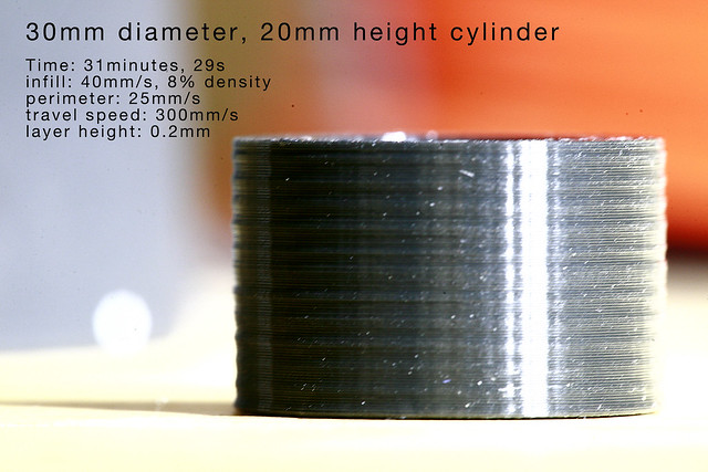
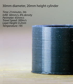
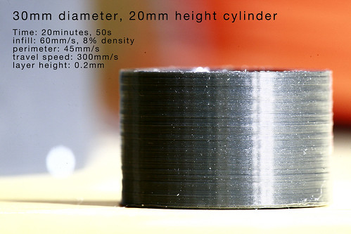
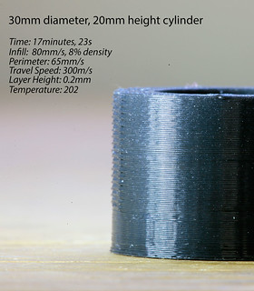
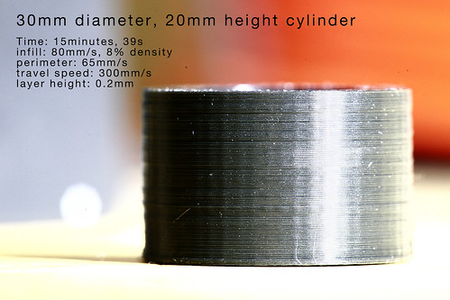
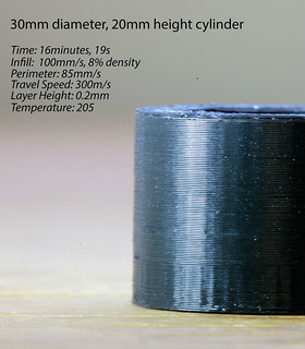
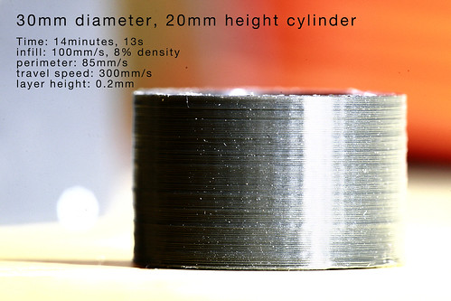
Here are the results of the same cylinder test that we used. New setup on the left, old on the right. The sets go 40mms/ 60mms/ 80mms/ 100mms

___________________________________________________
Kreativ-e
Tinkerine Studio
___________________________________________________
Kreativ-e
Tinkerine Studio
|
Re: Z Motor setup comparison August 20, 2012 04:00PM |
Registered: 12 years ago Posts: 108 |
|
Re: Z Motor setup comparison August 20, 2012 04:16PM |
Registered: 13 years ago Posts: 141 |
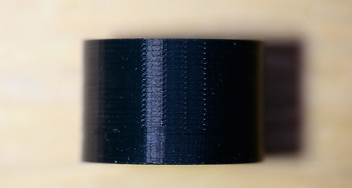
Thanks Mazaw, when you say jitters, are you referring to the ridges on the left? If so those are where the layers met and where the clip occurs in the print. Each of the prints have one of these points, When didnt notice the orientation of the photo when we took it. The below photo is what I am talking about
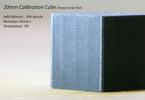
Heres another update of the print quality we did on a calibration cube. Who doesnt love some good looking squares?
___________________________________________________
Kreativ-e
Tinkerine Studio
Heres another update of the print quality we did on a calibration cube. Who doesnt love some good looking squares?
___________________________________________________
Kreativ-e
Tinkerine Studio
|
Re: Z Motor setup comparison August 21, 2012 05:58AM |
Registered: 13 years ago Posts: 7,616 |
Quote
Any idea what caused that jitter on the 17 minute (third) print?
Looks like the choosen feedrates hit some printer resonance.
Regarding these motors ... where is the stepper motor shaft? I'm aware of motors which have a nut inside instead of a shaft, but then the rod whould go below the table on low Z levels.
| Generation 7 Electronics | Teacup Firmware | RepRap DIY |
|
Re: Z Motor setup comparison August 21, 2012 01:27PM |
Registered: 13 years ago Posts: 141 |
the leadscrew is the motor shaft, an there is no extra length that protrudes the other side of the motor.
Edited 1 time(s). Last edit at 08/21/2012 01:27PM by ECSuyu.
___________________________________________________
Kreativ-e
Tinkerine Studio
Edited 1 time(s). Last edit at 08/21/2012 01:27PM by ECSuyu.
___________________________________________________
Kreativ-e
Tinkerine Studio
|
Re: Z Motor setup comparison August 22, 2012 03:31PM |
Registered: 13 years ago Posts: 141 |
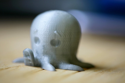
Heres a test we did at 100 microns layers (0.1mm)
___________________________________________________
Kreativ-e
Tinkerine Studio
___________________________________________________
Kreativ-e
Tinkerine Studio
|
Re: Z Motor setup comparison June 09, 2013 05:34AM |
Registered: 13 years ago Posts: 74 |
You need a better NUT than the bronze nut for a much better performance.
[www.robotdigg.com]
[www.robotdigg.com]
|
Re: Z Motor setup comparison June 09, 2013 05:54AM |
Registered: 11 years ago Posts: 248 |
question is if these acme setuup was done right..
for example, i use longer nuts, on my cnc mill(M16), and they will also be on my 3d printer(working in progres.)
and they are alot better than these normal ones...
on my mill tolerances on meassured cutted part are -/+0.2 mm
about coupler. when you use this coupler, acme screw must be axially fixed with bearing. becouse that cutted spiral plays, i know, i have them too.
for example, i use longer nuts, on my cnc mill(M16), and they will also be on my 3d printer(working in progres.)
and they are alot better than these normal ones...

on my mill tolerances on meassured cutted part are -/+0.2 mm
about coupler. when you use this coupler, acme screw must be axially fixed with bearing. becouse that cutted spiral plays, i know, i have them too.
Sorry, only registered users may post in this forum.