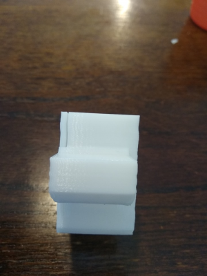
My print is so wavy
Posted by Keshan
My print is so wavy August 30, 2019 08:47PM |
Registered: 6 years ago Posts: 11 |
Just finish a print and it's just so wavy
I put back my sbase 1.3 on my D-bot with external TMC2208 on XYZ and DRV8825 for E
the current I set to 480mA for XY and 780mA for Z, after this print I increase the current on XY to 700mA but the wavy is still there.
I enabled linear advance with K value at 0.1
JUNCTION_DEVIATION_MM 0.022 or should I use Jerk?
enabled S_CURVE_ACCELERATION
Other parameters that I think might have an impact on print quality?
#define DEFAULT_MAX_FEEDRATE { 500, 500, 100, 50 }
#define DEFAULT_MAX_ACCELERATION { 2000, 2000, 100, 2000 }
#define DEFAULT_ACCELERATION 2000
#define DEFAULT_RETRACT_ACCELERATION 3000
#define DEFAULT_TRAVEL_ACCELERATION 2000
I am not sure where I should start to debug the problem, could it be the slicing software? or belt tension?
input is really appreciated, thanks.
Edited 1 time(s). Last edit at 08/30/2019 08:49PM by Keshan.
Re: My print is so wavy September 02, 2019 12:40AM |
Registered: 4 years ago Posts: 2 |
Re: My print is so wavy September 02, 2019 04:57AM |
Registered: 4 years ago Posts: 9 |
Also check the grub screws on pulleys are good as well as bearing of idlers.
[github.com] - #BearUpgrade
[github.com] - #BearUpgrade
Re: My print is so wavy September 06, 2019 07:14AM |
Registered: 8 years ago Posts: 413 |
Think we need some more clues.
What way up and directions for the printed part. I assume its wavy in the Z axis, is the error in both x and Y or just one direction.
Often its hardware related and particularly the z axis constraints. So look for off centre leadscrews, over constrained lead screws (the guid rods are the guides not the lead screws), dodgy bearings etc.
Re: My print is so wavy September 06, 2019 09:08AM |
Registered: 6 years ago Posts: 1,863 |
Quote
MCcarman
Think we need some more clues.
What way up and directions for the printed part. I assume its wavy in the Z axis, is the error in both x and Y or just one direction.
Often its hardware related and particularly the z axis constraints. So look for off centre leadscrews, over constrained lead screws (the guid rods are the guides not the lead screws), dodgy bearings etc.
I concur, though it is difficult to say for sure with a single image on such a dark background. Including more images plus an image of the STL model to see what the original looks like would help.
On my 3D Printer I wrapped the end of the lead-screw with electrician tape and then carefully press it into the coupler to assure a perfect circular path for the lead-screws,
leaving all fasteners loose and adjusted the Z axis up to tightening the top bolts and down to tighten the bottom bolts, all the time making sure the lead-screws were not binding.
Then finally the wavy lines on all my models were gone, However I still has infill overlap that was causing artifacting and finally adjusted the slicers infill overlap parameters to correct.
Finally setting up junction deviation and s curve acceleration came up with prints that are nearly perfect in every way. For my Hictop 3DP11/12 Cartesian Prusa i3 compatible - 3D Printers.
#define JUNCTION_DEVIATION_MM 0.06
#define S_CURVE_ACCELERATION
The latter also allowed me a higher rate of print speed without shacking this Hictop 3DP11/12 Cartesian Prusa i3 compatible - 3D Printer apart.
Edited 1 time(s). Last edit at 09/06/2019 09:11AM by Roberts_Clif.
Computer Programmer / Electronics Technician
Sorry, only registered users may post in this forum.
