New 3D Printer Design: Arm-based, able to make electronics full auto
Posted by daveycrocket
|
New 3D Printer Design: Arm-based, able to make electronics full auto September 28, 2012 08:25AM |
Registered: 11 years ago Posts: 10 |
So, I have this idea I want to share and get some feedback on. I've been doing some research on how to build low-cost industrial robotics for the last few months. In the process, I came up with this design for a 3D printer based on an arm design.
So, I have two reasons for posting.
1) I want to see if there is interest in a cheap, fully-automated electronic board maker + 3D printer and
2) I could use some advice on the design in case I'm making glaring mistakes. I've done the math, and assuming my tolerances are good and it doesn't bend a lot, I can achieve the same precision and better than a regular XYZ stage 3D printer.
Here is the design. (attached image)
So, why a circular/cylindrical design?
1) This allows a huge build area and work area. 3 feet in diameter if the arm is 1.5 feet long. 7 square feet! You could print statues
2) The robotic arm can use the extra work area to do other things, like:
A) pick up parts that finished printing and put them in a bin, then continue to make other parts.
 Use the build space to make electronics: etch in one section, clean water bath in another, a dirty container for adding liquid tin to the board, a toaster oven or something for solder reflow, etc. I've also figured out how to use steppers in a way that allows it to be both high-speed and high precision!
C) The arm could be used to automate other things besides the stuff mentioned above. Someday, I'd like to build low-cost industrial arms.
So, how would the fully-automatic electronic board building work?
I want to create a system where you can go online, download a BOM list of electronic components. Send it to a supplier and buy the components for an arduino mega board for $10 or $20, whatever it may be. Then, you get a $5 copper clad pcb with scratch-off resist for use with an etching scriber (also build into the arm) to make the etch pattern. When you get the parts, you lay them on the robot arm's work area. secure the board for putting the etch pattern on and lay all the components with their faces up. The arm will use an on-board camera to capture images of the board and components. It will have reference images from the internet, or you could teach it to recognize new components using a simple interface that comes with the arm. Then, it removes resist from the PCB to make the circuit pattern use a sharp tool to scratch off resist. It then moves the part to an automated etch bath, while monitoring its progress with a camera. Next, it causes the board to be moved to clean water to clean off the acid, now that the circuit pattern is complete. Once clean, it moves it to the next station: a tinning container (although not sure how necessary this is). Once tinned, it moves it back to the spot where the PCB can be securely in place. It applies solder paste using an attached syringe. Next, it uses a suction attachment to pick up and place electronic components. I have experience with computer vision and can probably write all of this code to do the matching of the electronic components and verifying that their placement on the board is correct. Once all the parts are placed, it lifts the board and places it in a reflow oven or modified toaster oven When the meal is done, it removes the board and puts it in the completed bin
I imagine that you could walk away and come back a couple hours later with a finished arduino mega for $20 worth of stuff. Imagine what it could do for making electronics that normally cost hundreds like a professional stepper motor controller. It would also be really great for prototyping electronics. At the moment, making PCBs is such a royal PITA, that its not worth doing to the vast majority of people.
This system could cost probably just $1000 to allow it to do all the above. What do you guys think? worth doing?
So, I have two reasons for posting.
1) I want to see if there is interest in a cheap, fully-automated electronic board maker + 3D printer and
2) I could use some advice on the design in case I'm making glaring mistakes. I've done the math, and assuming my tolerances are good and it doesn't bend a lot, I can achieve the same precision and better than a regular XYZ stage 3D printer.
Here is the design. (attached image)

So, why a circular/cylindrical design?
1) This allows a huge build area and work area. 3 feet in diameter if the arm is 1.5 feet long. 7 square feet! You could print statues
2) The robotic arm can use the extra work area to do other things, like:
A) pick up parts that finished printing and put them in a bin, then continue to make other parts.
Use the build space to make electronics: etch in one section, clean water bath in another, a dirty container for adding liquid tin to the board, a toaster oven or something for solder reflow, etc. I've also figured out how to use steppers in a way that allows it to be both high-speed and high precision!C) The arm could be used to automate other things besides the stuff mentioned above. Someday, I'd like to build low-cost industrial arms.
So, how would the fully-automatic electronic board building work?
I want to create a system where you can go online, download a BOM list of electronic components. Send it to a supplier and buy the components for an arduino mega board for $10 or $20, whatever it may be. Then, you get a $5 copper clad pcb with scratch-off resist for use with an etching scriber (also build into the arm) to make the etch pattern. When you get the parts, you lay them on the robot arm's work area. secure the board for putting the etch pattern on and lay all the components with their faces up. The arm will use an on-board camera to capture images of the board and components. It will have reference images from the internet, or you could teach it to recognize new components using a simple interface that comes with the arm. Then, it removes resist from the PCB to make the circuit pattern use a sharp tool to scratch off resist. It then moves the part to an automated etch bath, while monitoring its progress with a camera. Next, it causes the board to be moved to clean water to clean off the acid, now that the circuit pattern is complete. Once clean, it moves it to the next station: a tinning container (although not sure how necessary this is). Once tinned, it moves it back to the spot where the PCB can be securely in place. It applies solder paste using an attached syringe. Next, it uses a suction attachment to pick up and place electronic components. I have experience with computer vision and can probably write all of this code to do the matching of the electronic components and verifying that their placement on the board is correct. Once all the parts are placed, it lifts the board and places it in a reflow oven or modified toaster oven
When the meal is done, it removes the board and puts it in the completed bin I imagine that you could walk away and come back a couple hours later with a finished arduino mega for $20 worth of stuff. Imagine what it could do for making electronics that normally cost hundreds like a professional stepper motor controller. It would also be really great for prototyping electronics. At the moment, making PCBs is such a royal PITA, that its not worth doing to the vast majority of people.
This system could cost probably just $1000 to allow it to do all the above. What do you guys think? worth doing?
|
Re: New 3D Printer Design: Arm-based, able to make electronics full auto September 28, 2012 10:52AM |
Registered: 11 years ago Posts: 1,277 |
Man, with a printing surface that large it will have a ton of issues with lifting to speed (it better be fast or cooling will set in and the surface could be hard before it swings back around for another pass). I bet there would be even more issues just these two come quickly to mind for something that big that can print (I wish it would work though as I am an advocate of larger and faster printing to make it truly viable for at least my needs).
_______
I await Skynet and my last vision will be of a RepRap self replicating the robots that is destroying the human race.
_______
I await Skynet and my last vision will be of a RepRap self replicating the robots that is destroying the human race.
|
Re: New 3D Printer Design: Arm-based, able to make electronics full auto September 28, 2012 06:45PM |
It's a good idea, wither or not it will work *accurately* is another thing. I have a CNC Mill, I know there are more forces at work in a mill, but you wouldn't belive how much the end of YOUR arm WILL sag down, my guess is more than 1-3 layers when it's at the end of the arm, now you can build an angular brace ontop, but at what cost? you want strong material, but metal isn't lightweight....
Why not do a design similar to the recent Kick Starter I just seen.
[www.kickstarter.com]
Their arm is square tubeing which is stronger than your design.
Why not do a design similar to the recent Kick Starter I just seen.
[www.kickstarter.com]
Their arm is square tubeing which is stronger than your design.
|
Re: New 3D Printer Design: Arm-based, able to make electronics full auto September 29, 2012 04:05AM |
Registered: 13 years ago Posts: 1,352 |
I wouldnt dismiss the ideea just coz of the sag of the long arm. Thats not hard to model and should be fairly easy to implement firmware compensation, e.g. moves to the tip track a Z lift accordingly. The movements would be intricate to implement, but certainly not impossible.
The mechanical issue i would be more concerned with is the micro-monumental ratio for the incremental movement at the base to rotate the tip with the desired machine resolution. Besides limiting resolution a lot, mechanically feels quite hard to achieve and probably wont work with plastic parts either.
So i'd say the *one* circle movement has to change, and its replaceable with a linear type stage. At this point i guess we pretty much end up with a more or less cartesian type gantry which is only suspended to one side, something that does look like an "arm", something that is more spectacular than effective. Other than replacing one circle with a linear stage, it can be replaced by 2 circles, which i believe would be something like a scara type, and also would make the tip resolution more effective and/or practical.
|
Re: New 3D Printer Design: Arm-based, able to make electronics full auto September 29, 2012 04:34AM |
Registered: 12 years ago Posts: 539 |

|
Re: New 3D Printer Design: Arm-based, able to make electronics full auto September 29, 2012 04:46AM |
Registered: 12 years ago Posts: 1,236 |
daveycrocket Wrote:
-------------------------------------------------------
> 2) I could use some advice on the design in case
> I'm making glaring mistakes. I've done the math,
> and assuming my tolerances are good and it doesn't
> bend a lot, I can achieve the same precision and
> better than a regular XYZ stage 3D printer.
It's an ambitious project with some worthwhile goals, but are you sure you have done all the math? To get a resolution of 0.1mm at the outer reach of the arm, the arm length is limited to about 25mm. You would need at least a jointed arm.
I would split up the project into some sub-projects. Just getting the mechanics to work well is a project in itself, there is some good stuff here [www.heliumfrog.net63.net]
A pick and place attachment for a cartesion robot would also be a good project, it's on my back burner. A cheap and good video recognition system would be really useful!
|
Re: New 3D Printer Design: Arm-based, able to make electronics full auto September 29, 2012 06:12AM |
Registered: 11 years ago Posts: 1,277 |
NoobMan Wrote:
-------------------------------------------------------
> I wouldnt dismiss the ideea just coz of the sag of
> the long arm. Thats not hard to model and should
> be fairly easy to implement firmware compensation,
> e.g. moves to the tip track a Z lift accordingly.
> The movements would be intricate to implement, but
> certainly not impossible.
>
> The mechanical issue i would be more concerned
> with is the micro-monumental ratio for the
> incremental movement at the base to rotate the tip
> with the desired machine resolution. Besides
> limiting resolution a lot, mechanically feels
> quite hard to achieve and probably wont work with
> plastic parts either.
>
> So i'd say the *one* circle movement has to
> change, and its replaceable with a linear type
> stage. At this point i guess we pretty much end up
> with a more or less cartesian type gantry which is
> only suspended to one side, something that does
> look like an "arm", something that is more
> spectacular than effective. Other than replacing
> one circle with a linear stage, it can be replaced
> by 2 circles, which i believe would be something
> like a scara type, and also would make the tip
> resolution more effective and/or practical.
Isn't that saying that steppers could not be used and we would need servos that can tell us exactly where it is without guessing, and hoping, like we do with steppers?
_______
I await Skynet and my last vision will be of a RepRap self replicating the robots that is destroying the human race.
|
Re: New 3D Printer Design: Arm-based, able to make electronics full auto September 29, 2012 10:05AM |
Registered: 13 years ago Posts: 1,797 |
|
Re: New 3D Printer Design: Arm-based, able to make electronics full auto September 29, 2012 10:15AM |
Registered: 11 years ago Posts: 10 |
Yeah, you know what. I thought more carefully about it and realized its just not worth the trouble to use an arm design because you can achieve the exact same things with an XYZ stage that is shapeoko-style (where the tool/extruder moves and the base doesn't). There is so much uncertainty in the design, it would take too much of my time and energy to see if it would work. There's no reason you couldn't make a long xyz stage and achieve the same thing. So, here's what I'm thinking now, make one of the axes extra long and put the stuff for making PCBs (acid bath, clean water bath, toaster oven, etc) on a different section that is still within the xzy stage. \
I also have this idea of using two stepper motors per axis to achieve higher speeds. So, you could really achieve more than double the speed of the shapeoko style, while being able to slow down and get high accuracy when you want it.
I'm definitely going to work on the fully automated PCB fabrication + pick and place stuff. I know others have worked on it. So, I'll try to jump in where they left off. I think my key contribution will be the computer vision to be able to lay out components on the XYZ table, rather than using precisely positioned reels of components. Because no one is going to buy a whole reel if they are just making one board for themselves. It just doesn't make sense to use reels for short runs.
|
Re: New 3D Printer Design: Arm-based, able to make electronics full auto September 30, 2012 02:35AM |
Registered: 11 years ago Posts: 173 |
|
Re: New 3D Printer Design: Arm-based, able to make electronics full auto September 30, 2012 04:59AM |
Registered: 13 years ago Posts: 1,797 |
|
Re: New 3D Printer Design: Arm-based, able to make electronics full auto October 04, 2012 09:59AM |
Registered: 11 years ago Posts: 10 |
|
Re: New 3D Printer Design: Arm-based, able to make electronics full auto October 04, 2012 10:31AM |
Registered: 11 years ago Posts: 124 |
BAMCNC Wrote:
-------------------------------------------------------
> It's a good idea, wither or not it will work
> *accurately* is another thing. I have a CNC Mill,
> I know there are more forces at work in a mill,
> but you wouldn't belive how much the end of YOUR
> arm WILL sag down, my guess is more than 1-3
> layers when it's at the end of the arm,
I was thinking the same thing, easy to fix though. It doesnt have to use an "arm" why not a bar that goes all the way and is anchored on both sides of the enclosure? solves the problem.
The rotating print bed idea is pretty neat, I think it might be more stable than having a Y bed move back and forth all the time. It would have to stay perfectly perpendicular while rotating though. Interesting design I think you should try a small scale version.
|
Re: New 3D Printer Design: Arm-based, able to make electronics full auto October 08, 2012 11:42AM |
Registered: 11 years ago Posts: 10 |
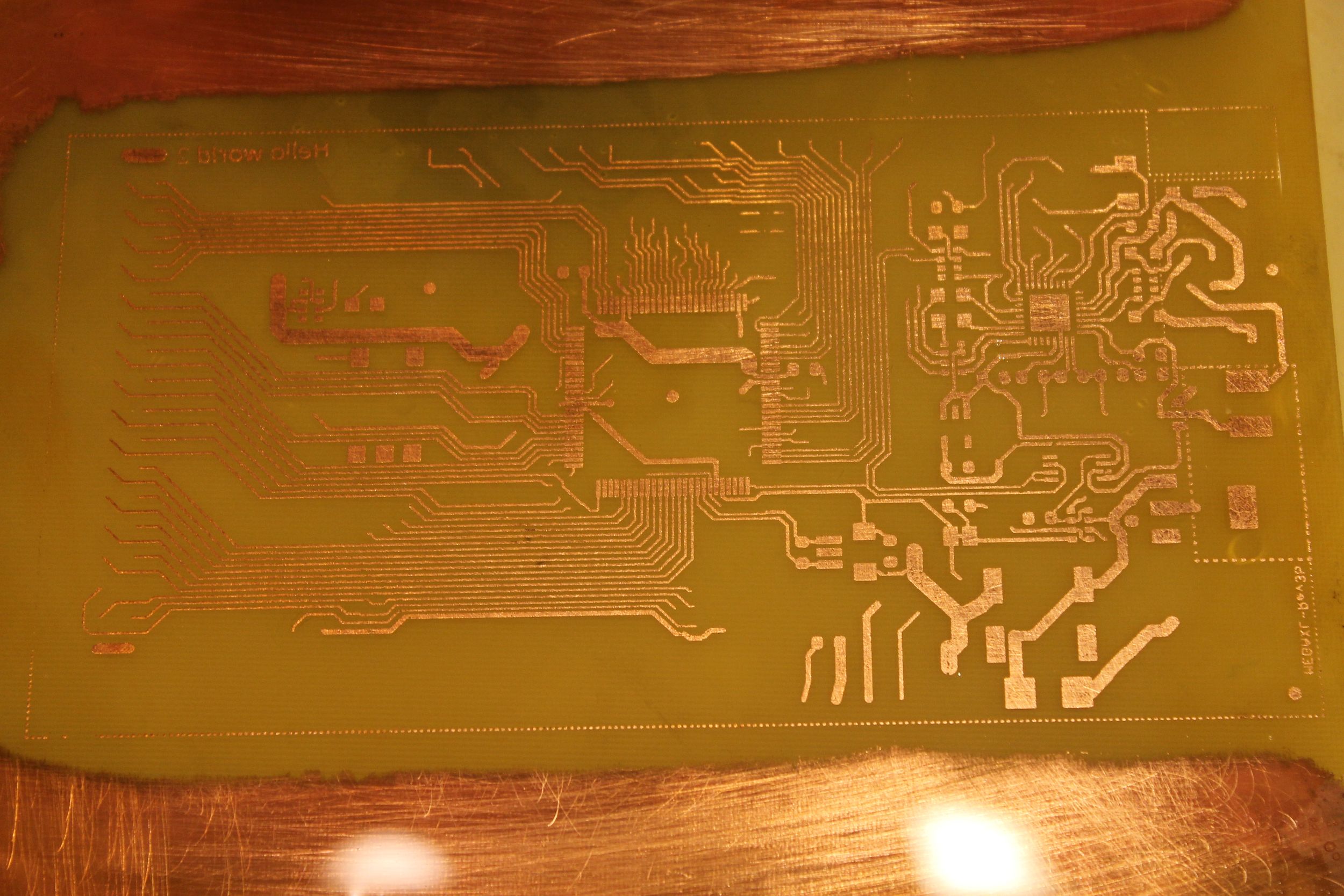
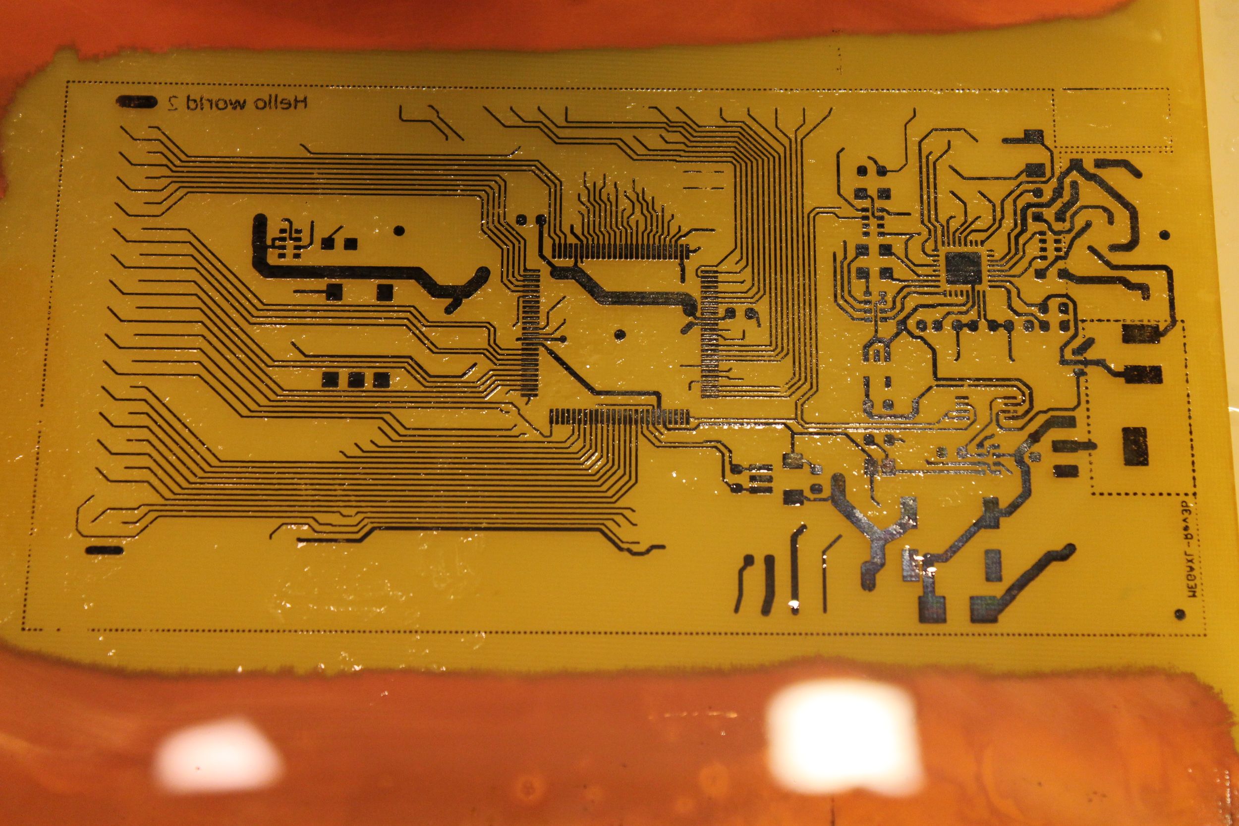
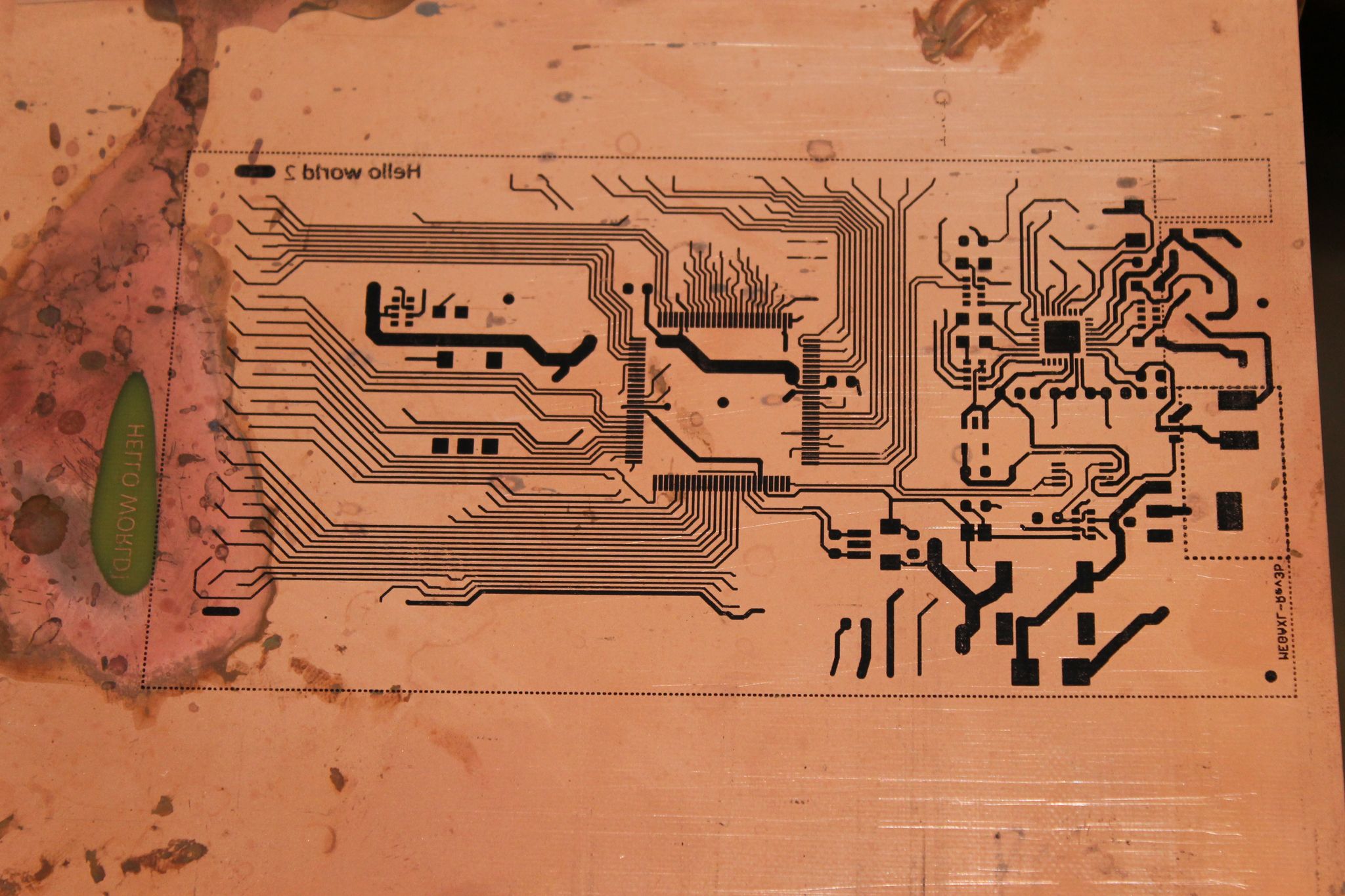
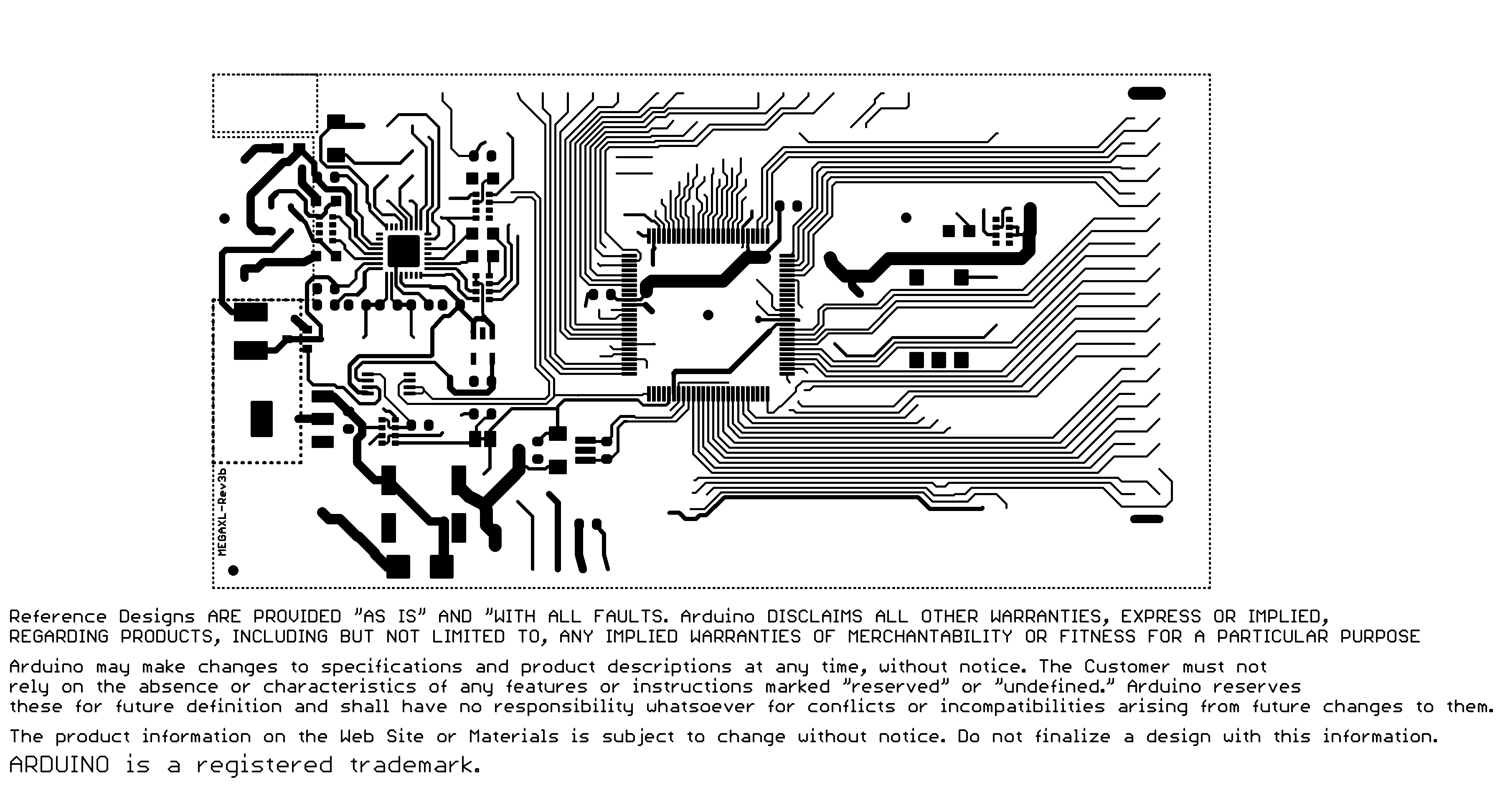
I successfully modified a laser printer to easily create patterns for PCBs. No ironing required!! I got it to print on transparencies without fusing it with heat. In other words, the ink is still "wet" (can smear). I also modified it so that the printer's rollers don't smear it as it comes out of the printer. This makes it easy to transfer to a PCB because it doesn't require ironing and crap. You just charge up the board with static and rub the transparency with your nail to get 100% transfer reliably. Sometimes you don't have to rub, but rubbing it is more reliable.
Attached are some images of the patterns I created. I'm going to be working on fully automating it. I'm considering to sell the modified printers to encourage me to keep making progress. The next step would be to automate the alignment and fixing of the toner to the PCB. From there it should be super simple to automate the etch process and I'd be well on my way to creating the first reprap to also make its own RAMPS board!
Edited 1 time(s). Last edit at 10/08/2012 11:44AM by daveycrocket.
|
Re: New 3D Printer Design: Arm-based, able to make electronics full auto October 08, 2012 12:01PM |
Registered: 11 years ago Posts: 1,277 |
|
Re: New 3D Printer Design: Arm-based, able to make electronics full auto October 08, 2012 12:33PM |
Registered: 13 years ago Posts: 1,797 |
can you show a board etched? i use to do laser toner transfer method, and even use to sell units that baked the toner onto copper boards. there are issues if you don't fuse the toner onto a board, it lifts off during etch. perhaps you have it bake dry, or what is the dry time before etch?
also some newer lasers that use different plastics powders do not work for this method.
also some newer lasers that use different plastics powders do not work for this method.
|
Re: New 3D Printer Design: Arm-based, able to make electronics full auto October 08, 2012 02:00PM |
Registered: 11 years ago Posts: 16 |
Good ideas floating around guys.
With regards to pick and place Patrick over at buildyourcnc.com has already put a lot of time and effort into this area. If you take a look atBuildyourcnc you'll see it all there. His gantry moves over a stationary bed and even takes the parts from the reels. He uses a skillet to reflow solder.
Worth having a look at his stuff as you can buy parts/plans/kits off him and your half way there!
Tom
|
Re: New 3D Printer Design: Arm-based, able to make electronics full auto October 08, 2012 06:20PM |
Admin Registered: 13 years ago Posts: 730 |
Nice work, davey. I really like to see the new methods people come up with on this forum.
How do you charge up the board with static? Do you think an electrostatic-based method could work with some type of simple powder depositing mechanism, simpler than a laser printer?
Not to discourage you in your quest, but repraps already can make their own RAMPS boards. If you check out Automated Circuitry Making there is a picture of a RAMPS board that was made on a Mendel and later used to control a Mendel.
Also of interest might be these direct-to-pcb projects using inkjet printers:
printing pcbs on a junked epson printer
direct to pcb etch resist printing
PS - Would you be able to add your system to the Automated Circuitry Making wiki page? I would like to know more about it (as would many others here, I expect).
|
Re: New 3D Printer Design: Arm-based, able to make electronics full auto October 08, 2012 06:30PM |
Registered: 11 years ago Posts: 1,277 |
I have a question about all of this. Couldn't a CNC do all of this without any etching needed? I etched a few boards in my day and it was cool but a PITA at the same time with the transfer using an iron (this was back with dot matrix printers) and the acid that needed to be slightly warm and agitated, etc...
I am sure that a CNC could etch the copper off (it is only a thin layer after all) and even drill the holes in the middle of the pads too.
_______
I await Skynet and my last vision will be of a RepRap self replicating the robots that is destroying the human race.
I am sure that a CNC could etch the copper off (it is only a thin layer after all) and even drill the holes in the middle of the pads too.
_______
I await Skynet and my last vision will be of a RepRap self replicating the robots that is destroying the human race.
|
Re: New 3D Printer Design: Arm-based, able to make electronics full auto October 08, 2012 06:41PM |
Admin Registered: 13 years ago Posts: 730 |
A CNC can certainly mill boards. A reprap can too, if it is fitted with a milling head.
Check out PCB Milling and Milling and Drilling Head
Check out PCB Milling and Milling and Drilling Head
|
Re: New 3D Printer Design: Arm-based, able to make electronics full auto October 08, 2012 07:04PM |
Registered: 11 years ago Posts: 1,277 |
|
Re: New 3D Printer Design: Arm-based, able to make electronics full auto October 08, 2012 11:13PM |
Registered: 11 years ago Posts: 10 |
Finally finished etching. See attached. So, a few notes... This is the second board I've ever made. So, I'm a newbie still experimenting. I used ferric chloride and a sponge. The arduino board is supposed to be smaller than I printed it. Not all of the toner transferred over. Probably because I didn't rub it on every single spot since I just did it kind of randomly.
Note, if the laser printer doesn't create a perfect image on the board or transparency, you can wipe the transparency with paper towel and print again! Just line everything up and you'll double the amount of toner and coverage you get! It may even be smart to put it in the oven to fix the toner first before trying to transfer a second layer. I suspect this would be even more effective.
Here are my steps:
1) Use hacked laser printer to print out unfused (unheated and smearable) toner onto a transparency.
2) tape the transparency to the board, but keep a little board uncovered so I can transfer static electricity to the copper.
3) Charge up the board with a negative static electric charge.
I read that toner is positive and is therefore attracted to an electric charge. The simplest way I found to do this is to take a wool sweather and a small pvc pipe. Wrap the PVC pipe with the sweater tightly with your hand. Push the pipe through the sweater back and forth with pressure several times until you hear some static electricity popping sounds. Now, roll the part of the PVC pipe that was charged up over the exposed portion of the copper board. Since the copper is conductive, the charge will travel all the way down the board and pull the toner down off the transparency. You can also take the part of the sweater that was positively charge and try to rub the charge onto the transparency above the toner. This might help, but I'm not 100% sure it matters. Do this a few times. The board will become very strongly attracted to the transparency because of the charges. Next, use your nail or maybe a spoon to put pressure on the transparency where the toner is to make sure it bonds to the PCB and comes off of the transparency. My physics class on charge and wave physics was useful after all
4) Pull the transparency back, starting at one corner and slowly lift it. The toner should transfer 99.9%. If it doesn't, you can lay it back down and repeat step 3. Try charging the board again also, in case while you were rubbing the charge wore off into the moisture in the air.
5) Now that the toner is on the board, you need to heat it to melt the plastic in the toner onto the board. I put the board in the toaster oven on broil. Once it heated up, it actually over heated in a heartbeat! I'm not sure what the right temperature is. Try 450 degrees F and watch it carefully. You don't have to heat it long. Maybe just 30 seconds when the heat is really hitting the board well. The toner melts at 200 C. So, 400 F may even be enough. Especially because the oven will overheat it at first. burning the toner is not good for you, although probably not that bad either. So, try not to burn it.
I did consider milling, but I think you can achieve better precision with higher reliability, less fuss and less time with this sort of method. Milling has so many issues, like breaking of bits and leveling. The laser printer prints in half a second, the etching just takes a minute with ferric chloride, transferring the toner to the board could also be fast with a roller technique; fusing the toner to the board takes just a few seconds of heat. So, having a nice board in 5 minutes its pretty damn awesome. Do the other side and you've got a two sided PCB in 10 minutes. Milling just can't compete with that. I'm also planing to allow multiple-side boards with this technique.
Edited 6 time(s). Last edit at 10/10/2012 02:18PM by daveycrocket.
|
Re: New 3D Printer Design: Arm-based, able to make electronics full auto October 09, 2012 12:15AM |
Registered: 11 years ago Posts: 1,277 |
|
Re: New 3D Printer Design: Arm-based, able to make electronics full auto October 09, 2012 10:48AM |
Registered: 12 years ago Posts: 313 |
daveycrocket Wrote:
-------------------------------------------------------
> 2) I could use some advice on the design in case
> I'm making glaring mistakes. I've done the math,
> and assuming my tolerances are good and it doesn't
> bend a lot, I can achieve the same precision and
> better than a regular XYZ stage 3D printer.
>
> Here is the design. (attached image)
The linear stages don't look that different from the common cartesian bot designs, except that they are only supported at one end, which is going to make the construction pretty challenging (to put it mildly). The common Mendel/Prusa design already vibrates quite a bit from the dynamic loads, and it's an enclosed frame with every axis supported at both ends. To achieve the same precision as XYZ printers, you can't just look at the steps-per-mm resolution, it also has to accelerate a 100-500 g load at 1000-2000 mm/s*s to 200-300 mm/s speed and then decelerate just as rapidly, while achieving the 0.1 mm repeatable accuracy.
Anyway, I'm working on an arm-based design right now too. Here's a simulation moving around the edge of a 200x120 mm build plate:
In actual use these arms would be mounted on a carriage which moves linearly in Z. The arm joints are free joints, the large round bases are the only rotation mechanism.
And here's the first prototype moving: Parallel SCARA prototype
One thing I don't see is the usefulness of trying to build a fully automated electronics production line. If you have the design and BOM for a thing and need a bunch of them, just get them done commercially. It's not like there isn't enough competition in electronics production to keep the margins reasonable. (In a lot of the expensive-seeming items the BOM cost is just that high, in small batches anyway.) If you need a one-off, just handcraft it. Making nice PCBs from printed transparencies and hand-soldering many SMD components is something almost every hobbyist can do if needed.
-------------------------------------------------------
> 2) I could use some advice on the design in case
> I'm making glaring mistakes. I've done the math,
> and assuming my tolerances are good and it doesn't
> bend a lot, I can achieve the same precision and
> better than a regular XYZ stage 3D printer.
>
> Here is the design. (attached image)
The linear stages don't look that different from the common cartesian bot designs, except that they are only supported at one end, which is going to make the construction pretty challenging (to put it mildly). The common Mendel/Prusa design already vibrates quite a bit from the dynamic loads, and it's an enclosed frame with every axis supported at both ends. To achieve the same precision as XYZ printers, you can't just look at the steps-per-mm resolution, it also has to accelerate a 100-500 g load at 1000-2000 mm/s*s to 200-300 mm/s speed and then decelerate just as rapidly, while achieving the 0.1 mm repeatable accuracy.
Anyway, I'm working on an arm-based design right now too. Here's a simulation moving around the edge of a 200x120 mm build plate:

In actual use these arms would be mounted on a carriage which moves linearly in Z. The arm joints are free joints, the large round bases are the only rotation mechanism.
And here's the first prototype moving: Parallel SCARA prototype
One thing I don't see is the usefulness of trying to build a fully automated electronics production line. If you have the design and BOM for a thing and need a bunch of them, just get them done commercially. It's not like there isn't enough competition in electronics production to keep the margins reasonable. (In a lot of the expensive-seeming items the BOM cost is just that high, in small batches anyway.) If you need a one-off, just handcraft it. Making nice PCBs from printed transparencies and hand-soldering many SMD components is something almost every hobbyist can do if needed.
Sorry, only registered users may post in this forum.