Working on the Ifactory
Posted by garyhlucas
|
Working on the Ifactory February 06, 2013 02:04PM |
Registered: 11 years ago Posts: 205 |
I've been reading in the RepRap forums for a couple of weeks now. My 9 year old grandson keeps talking about building a robot, not knowing how much that involves. We went a FIRST robotics competition and he was a lot more interested than I expected. I'm an automation guy, with mechanical and electrical backgrounds. I want to pass that on to my grandson if I can.
The problem I have with 3D printing and the whole reprap concept is that you are only able to make parts of low accuracy, from a couple of materials, and the piece price is actually quite high. The idea that one printer can produce another is really only in your mind, 5% of all the parts needed does not a baby make! So I decided that a good first step towards builing a robot would be to first build the factory needed to make it.
On Ebay I got four THK GL20N linear slides with 18" of travel. At a scrap yard I got a 205 lb hand scraped cast iron surface plate 24" x 24" x 5-1/2" high (webbed on the bottom). From an old customer I got enough metric 40 T-slot material to build a heavy duty base 28" square, plus the material to build a complete enclosure 5' x 3' x 3 feet high (remember the 9 year old). He also gave me a couple hundred feet of IGUS robot servo cable for the motor connections, and a small DL06 PLC, 4 air valves and an air regulator. Also off Ebay I got a transformer, caps and bridge diodes to build a multi-voltage power supply, two steel electrical enclosures, Leadshine 7 amp 80 volt drives, four 800 in/oz steppers, and a USB breakout board. Finally I got a complete Sherline lathe with the milling column attachment and quite a bit of tooling.
I also happen to own a full size clapped out Bridgeport, and a really really sweet 10" 1950s SouthBend lathe in mint condition.
So the Ifactory will have:
A complete Sherline manual lathe and mill.
3 Linear Axis of 18" each, One rotary positionable axis, and a DC spindle.
CNC Vertical mill, with the Sherline spindle, the work will be stationary on the cast iron table.
CNC Horizontal mill by simply rotating the Sherline head. Can mill and drill the ends of very long parts. Chips fall out of the cut too.
CNC Vertical inverted lathe, with a lathe chuck on the Sherline spindle, and tooling mounted to the table.
CNC Horizontal Lathe with the Sherline spindle turned to the side, short parts only of course.
CNC Horizontal lathe between centers, with the Sherline lathe bed bolted to the table holding the spindle and tailstock.
CNC Cutoff saw, using a hacksaw blade on the Y axis and holding the part in a vice on the table.
CNC shaper for cutting key ways, dovetails etc.
CNC Stencil cutter using a knife mounted in the 4th axis spindle.
4 axis cartesian robot using a pnuematic gripper.
Filament Extruder, using the Sherline spindle with a CNC machined screw, mounted in a barrel on the Sherline dovetail way.
3D printer with 18" x 18" x 18" build capability.
Rhino, AutoCad, and Solid Edge 3D software that I already own
Mach 3 CNC software
Meshcam?
I bought my grandson his first tool box and some basic hand tools. We also got safety glasses, googles and ear plugs. Construction started last week. I have all the T-slot extrusions cut, milled square and machined for fasteners, we started assembling the base on Saturday. I hope to have the base done with the surface plate and guard framing done this weekend. Then I'll be able the position the surface plate and linear slides. I have to make new motor mounts, the slides have the wrong ones right now. I also have to make a connector between the X axis slide and the Z axis slide, which is the highest precision work needed. I've been working on that stuff at night. I'll post some pictures next week if anyone is interested.
My brain has been rotting away lately. Feels good to have a real project going!
Gary H. Lucas
|
Re: Working on the Ifactory February 06, 2013 02:14PM |
Registered: 11 years ago Posts: 374 |
Cool stuff man. I envy you to do automation for a living, and to have that full factory at your disposal. Nice. I plan on (very slowly) getting enough tabletop machinery to be fully capable of prototyping and hopefully launch a small family business from it.
I look forward to pics of what you are building man. Thanks for sharing!
-Dave
I look forward to pics of what you are building man. Thanks for sharing!
-Dave
|
Re: Working on the Ifactory February 06, 2013 03:06PM |
Registered: 11 years ago Posts: 250 |
Grandpa?!?!
is that you!!
Sounds like a great shop to play in.
I'd be late for dinner every night!
Southbends are nice machines, I have a SB 10k myself.
No bridgeport though but a RF40 with DRO.
Have fun with the build, it is half the fun after all!
--------------------------------------------------------
Custom all metal CoreXY
- Duet 2 Wifi w/ PanelDue 7i
- 330mm x 360mm x 500mm
- 750w Silicon heater
Custom Mendel90
(Backup printer - Old reliable!) - Sold
is that you!!
Sounds like a great shop to play in.
I'd be late for dinner every night!
Southbends are nice machines, I have a SB 10k myself.
No bridgeport though
but a RF40 with DRO.Have fun with the build, it is half the fun after all!
--------------------------------------------------------
Custom all metal CoreXY
- Duet 2 Wifi w/ PanelDue 7i
- 330mm x 360mm x 500mm
- 750w Silicon heater
Custom Mendel90
(Backup printer - Old reliable!) - Sold
|
Re: Working on the Ifactory February 06, 2013 07:35PM |
Registered: 11 years ago Posts: 490 |
Well, it's true that most of us don't build their machines with many printed parts although it is theoretically possible (see Beiwagerl). There is a trend towards non-printed parts, even. It is rather strange, too, that only few implemented milling since software and electronic hardware is quite interchangeable between printer and mill (at least on our DIY level).
I would really love to see pictures of your Ifactory as I am also interested in micro fabrication systems. Maybe some ideas can also be ported to improve RepRap?
Also, although you might already know this, there is someone working on a printed robot. The progress so far is rather impressive.
Edited 2 time(s). Last edit at 02/06/2013 08:10PM by uGen.
|
Re: Working on the Ifactory February 06, 2013 08:00PM |
Registered: 11 years ago Posts: 305 |
|
Re: Working on the Ifactory February 06, 2013 10:38PM |
Registered: 11 years ago Posts: 205 |
xclusive585 Wrote:
-------------------------------------------------------
> Cool stuff man. I envy you to do automation for a
> living, and to have that full factory at your
> disposal. Nice. I plan on (very slowly) getting
> enough tabletop machinery to be fully capable of
> prototyping and hopefully launch a small family
> business from it.
>
> I look forward to pics of what you are building
> man. Thanks for sharing!
>
> -Dave
Dave,
At the moment I work for a company designing and building waste water treatment systems using membranes, Ultrafilters and Reverse Osmosis. Twenty years ago though I my own company and we built a line of robot watering and spraying machines for the commercial greenhouse industry. Back then displays were very expensive, so the machines had a $25 speech synthesizer chip so they could speak! They had a 256 word vocabulary and could give you a report of what all the settings were, and what had been today. I got forced out by a bad deal with a larger company, but the machines are still being sold.
|
Re: Working on the Ifactory February 06, 2013 10:41PM |
Registered: 11 years ago Posts: 205 |
uGen Wrote:
-------------------------------------------------------
> Well, it's true that most of us don't build their
> machines with many printed parts although it is
> theoretically possible (see Beiwagerl). There is a
> trend towards non-printed parts, even. It is
> rather strange, too, that only few implemented
> milling since software and electronic hardware is
> quite interchangeable between printer and mill (at
> least on our DIY level).
>
> I would really love to see pictures of your
> Ifactory as I am also interested in micro
> fabrication systems. Maybe some ideas can also be
> ported to improve RepRap?
>
> Also, although you might already know this, there
> is someone working on a printed robot. The
> progress so far is rather impressive.
Yes, that is an impressive piece of work. It also takes advantage of the strengths of 3D printing, freeform organic shapes very difficult to machine from the solid.
|
Re: Working on the Ifactory February 06, 2013 10:50PM |
Registered: 11 years ago Posts: 205 |
Mogal Wrote:
-------------------------------------------------------
> Grandpa?!?!
> is that you!!
>
> Sounds like a great shop to play in.
> I'd be late for dinner every night!
>
> Southbends are nice machines, I have a SB 10k
> myself.
> No bridgeport though but a RF40 with DRO.
>
> Have fun with the build, it is half the fun after
> all!
I forgot to mention my bench vise. I was working for a company and we needed a good vise. So I started watching the want ads and such. I saw an ad for a Starrett vise and called the guy. I asked him if it was the good model or the cheaper junk version. He said it weighed about 150 lbs so I drove a hundred miles to get it. It is a top of the line Starrett weighing 200 lbs, for $150. Sells new for about $950. It was still in the box with steel banding all around, we opened it so I could see what it looked like. The company he worked for was scrapping 3 of them!
A great vise is incredibly useful. I push bearings in with this baby all the time.
I also have a 14" SOCO cold saw coming. It'll cut metal parts to length with a milled finish, and repeat to 0.001" over a whole batch. It is what the T-slot extrusion companies use. I used to use a ton of that stuff.
God I love good tools!
-------------------------------------------------------
> Grandpa?!?!
> is that you!!
>
> Sounds like a great shop to play in.
> I'd be late for dinner every night!
>
> Southbends are nice machines, I have a SB 10k
> myself.
> No bridgeport though
but a RF40 with DRO.>
> Have fun with the build, it is half the fun after
> all!
I forgot to mention my bench vise. I was working for a company and we needed a good vise. So I started watching the want ads and such. I saw an ad for a Starrett vise and called the guy. I asked him if it was the good model or the cheaper junk version. He said it weighed about 150 lbs so I drove a hundred miles to get it. It is a top of the line Starrett weighing 200 lbs, for $150. Sells new for about $950. It was still in the box with steel banding all around, we opened it so I could see what it looked like. The company he worked for was scrapping 3 of them!
A great vise is incredibly useful. I push bearings in with this baby all the time.
I also have a 14" SOCO cold saw coming. It'll cut metal parts to length with a milled finish, and repeat to 0.001" over a whole batch. It is what the T-slot extrusion companies use. I used to use a ton of that stuff.
God I love good tools!
|
Re: Working on the Ifactory, The foundations February 11, 2013 10:20PM |
Registered: 11 years ago Posts: 205 |
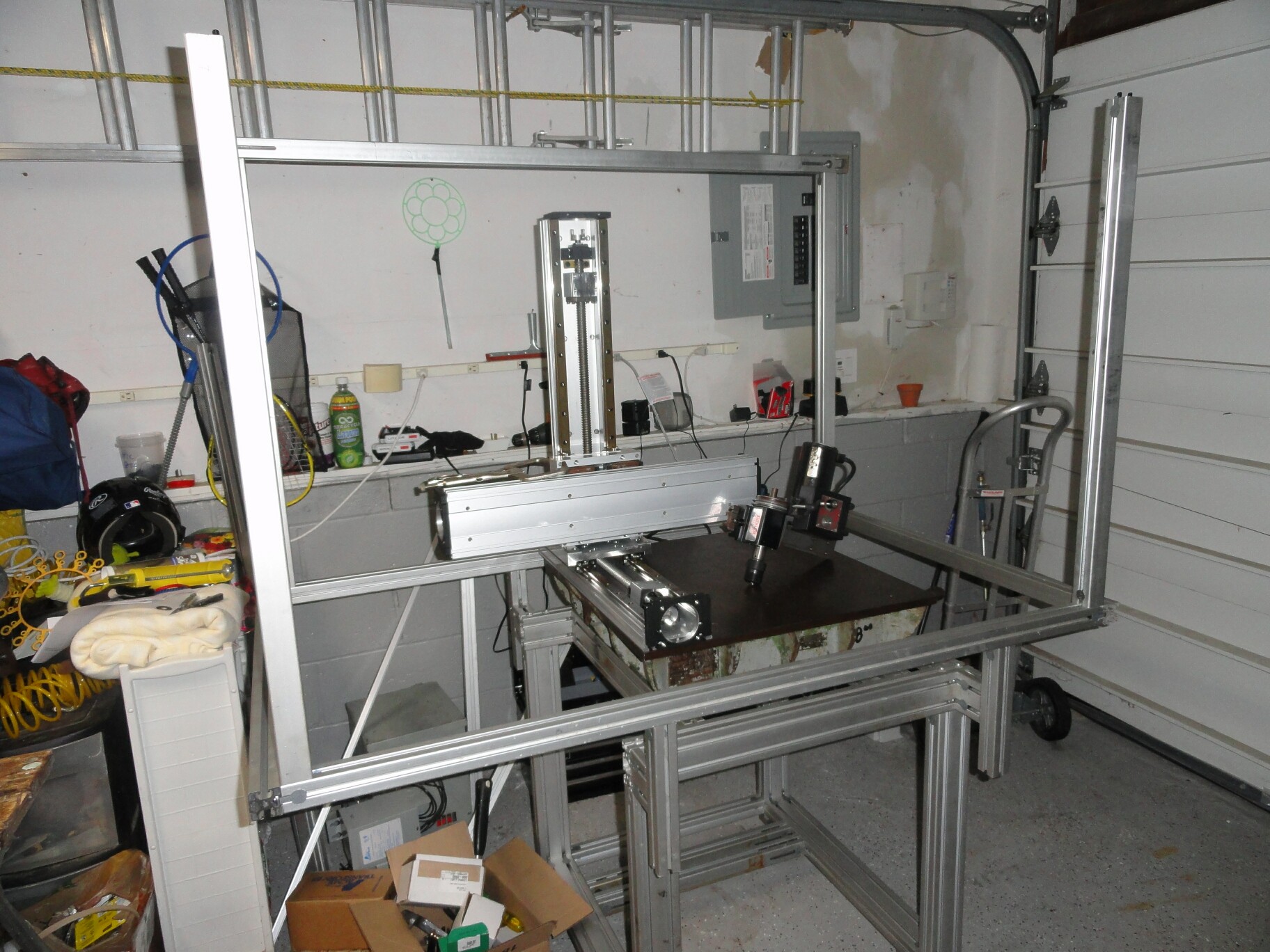
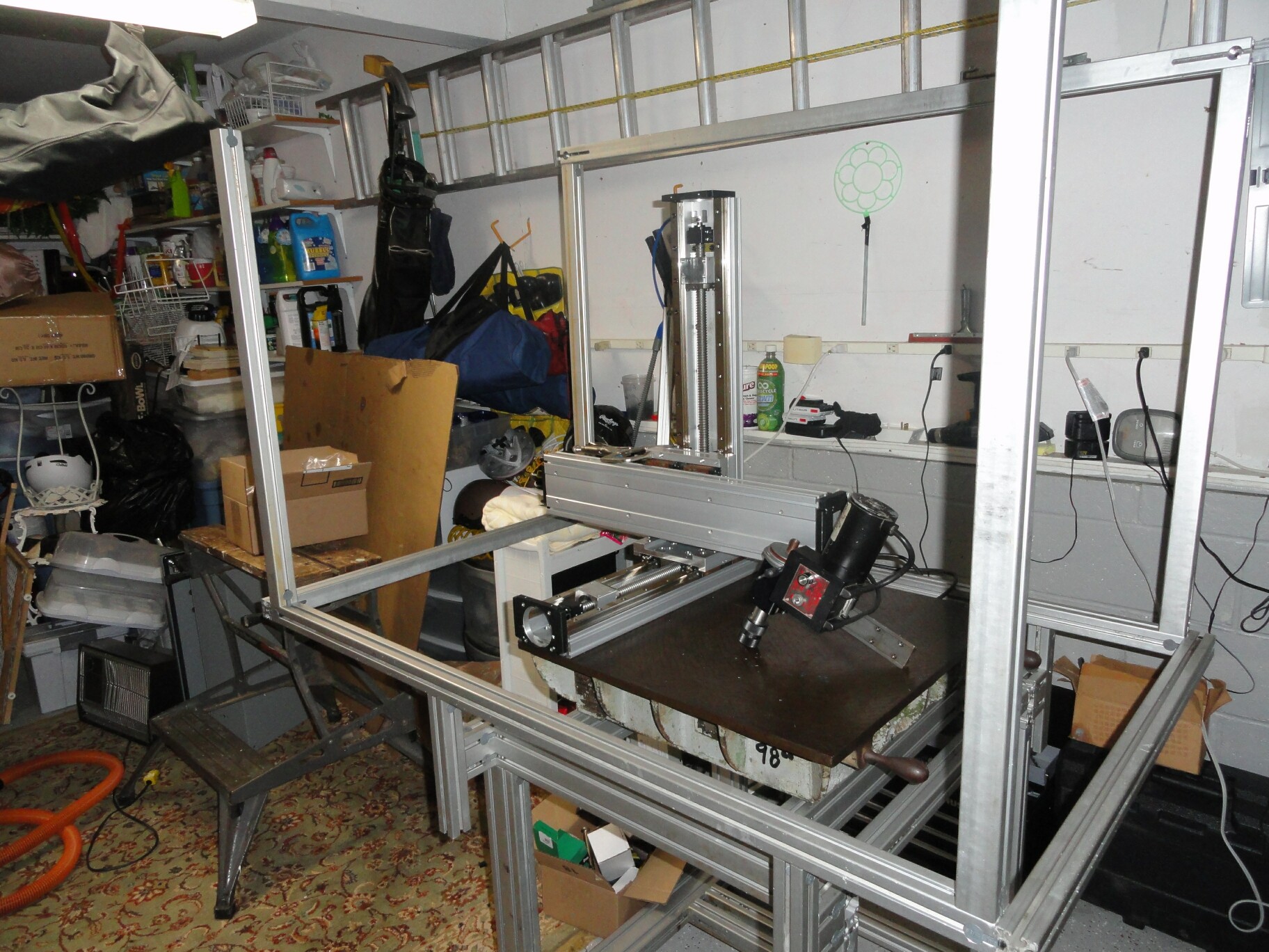
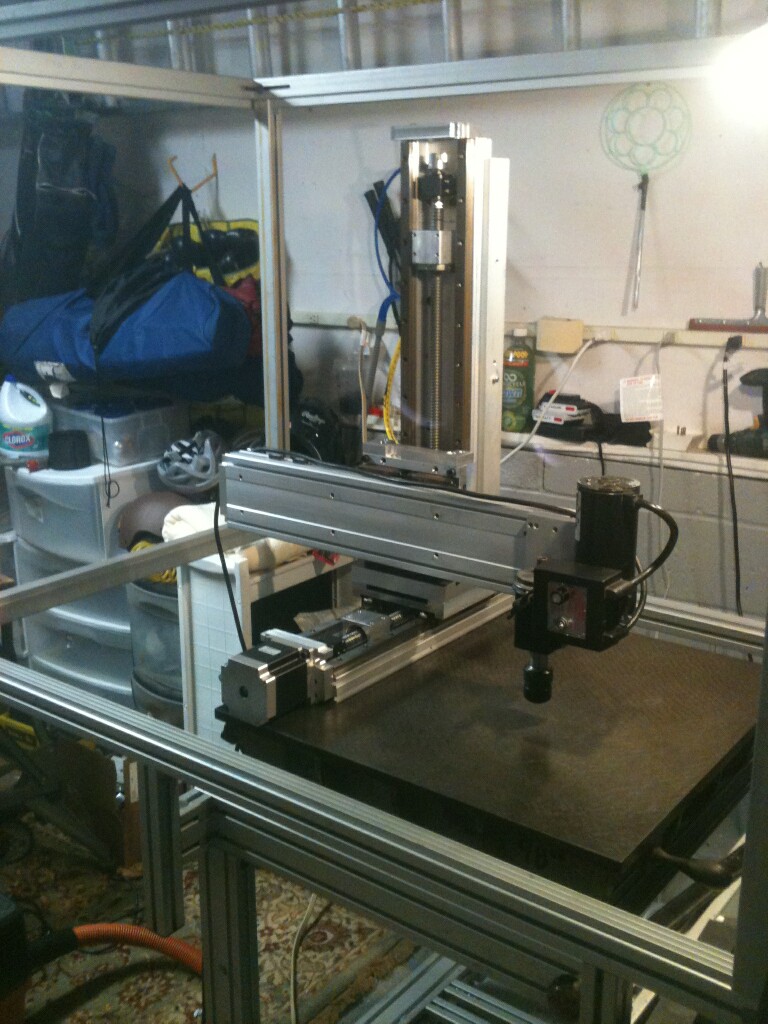
Well, I've finally gotten nearly every part for the factory and we've started construction. Over the weekend my grandson and I assembled the aluminum base, on Sunday I did most of the machining for the various adapters needed to assemble the slide. Tonight a friend came over and helped me set the table in place. Then I started on adding the enclosure framing. I roughly set the slides on the table in the appropriate locations and oriented them so you can see how the 3 axis are going to work. This is not a real space efficient system, however the work space is about 3' x 3' x 3' and machine travels are a true 18" x 18" x 18"
The aluminum framing was given to me, the table came from a scrap yard for $98, I got lots of other free parts. Bought lots of parts for way below cost, and I've still spent nearly 5K! Anxious to get it done.
The amazing thing is that since starting this project my brain has really been on fire, and I've had an amazing amount of energy. I'm going to be 60 soon, my current employers are idiots that have sucked all the joy out of my job, so this feels really good.
Gary H. Lucas
|
Re: Working on the Ifactory February 12, 2013 01:43AM |
Registered: 11 years ago Posts: 374 |
|
Re: Working on the Ifactory February 12, 2013 10:42PM |
Registered: 11 years ago Posts: 205 |
|
Re: Working on the Ifactory, The foundations February 17, 2013 04:42PM |
Registered: 11 years ago Posts: 3 |
|
Re: Working on the Ifactory February 18, 2013 11:41AM |
Registered: 12 years ago Posts: 539 |

|
Ifactory, progress report February 18, 2013 10:40PM |
Registered: 11 years ago Posts: 205 |
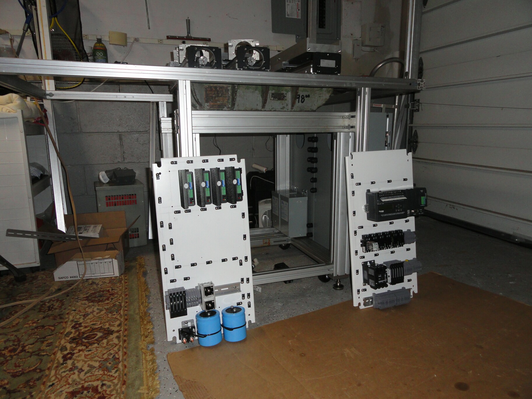
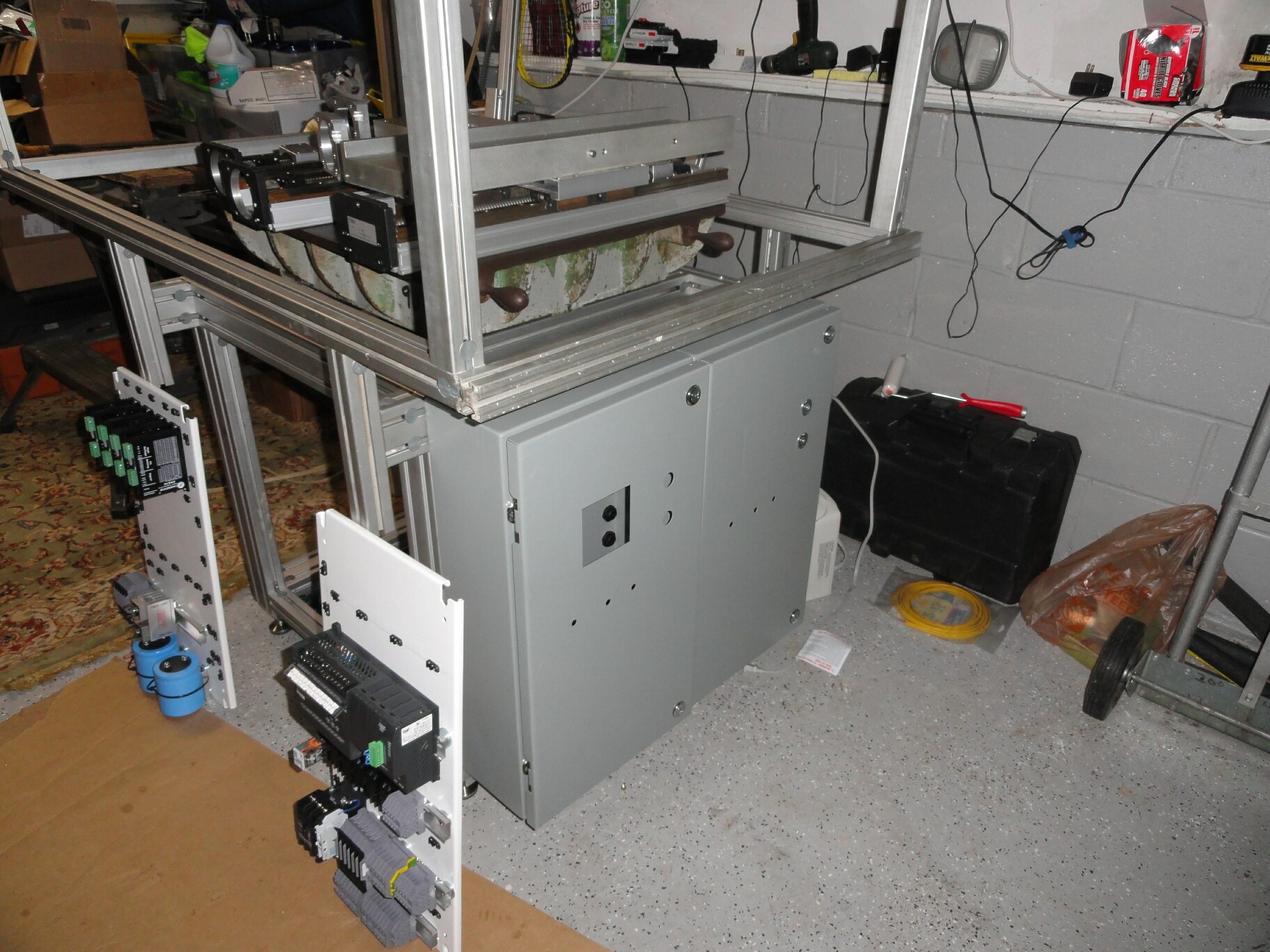
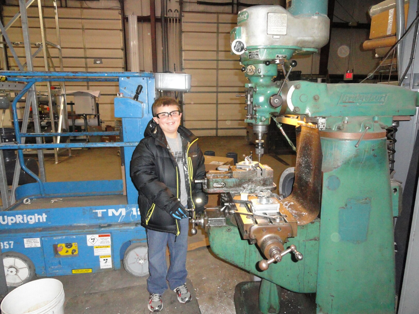
I've been pushing hard and the chief machinist Tyler seen here was a huge help on Saturday. We finished all the machined parts including the Z axis mounting plate and support plus three new motor mounts. Yesterday and today (took some vacation time) I worked on the electrical panels. Those two new surplus panels I paid $25 a piece for look like they were made for this machine! The front cutouts get plexiglas so you can see the display on the PLC and the temperature controller. As you can see I got nearly all the hardware mounted and wire tie bases installed. The guarding is problematic. I tried fiberglass panels for the back and one side, but they are way to flimsy. So now I'm going to use 1/4" MDF which is cheap, but needs to be painted. It's too cold to paint and have the smell in the garage so I'm going to have to wait on that.
I decided that I have a lot to learn about 3D printing and I want to get there fast, so I ordered an extruder with a hot end, a 12 vdc power supply, a temperature controller, silicone rubber bed heater and a 12" square base plate. So my printer will have a 12" x 12" x 18" tall workspace. I could put an 18" square bed on it in the future.
Every time I turn a round I find something else that costs a bundle. The servo cables I got for nothing were all defective. They had lots of use and when I started stripping them I found ruptured insulation in several places. So today I ordered some shielded cables for the motors. It tough getting small quantities of electrical parts at a good price. I am shocked at the cost of copper wire!
Not everything in the panels will be used. I don't know how everything will work so there is lots of redundancy and room for future. The PLC is currently unused, but I have ideas on using it in the future. I have circuits to power a pair of LED floods, a circuit for the cooling fan, one for the Sherline spindle motor, and one for an exhaust fan. There's also a filter regulator and valve manifold for air cylinders or a chip blowoff etc.
I have an unregulated DC power supply with two 750 va transformers that give me 17vdc, 34vdc, 51vdc, and 68vdc for the 80 volt rated stepper drivers. I may run different voltages for some axis. I have a 5vdc and 24vdc power supply for control power. Another 360watt 12vdc power supply runs the bed heater and the nozzle heater. I have it set up with two 15 amp 120 vac power cords to plug in to separate circuits, and can convert one to 240 power if I need to.
Safety is important here, so there is a master power contactor for the E-stop and all the various circuits are fused, including separate fuses for each drive. I have a young man working with me so the doors get switches so nothing can run unless they are closed.
Going out of town for a few days so no more will get done until next weekend.
|
Re: Working on the Ifactory February 19, 2013 09:31AM |
Registered: 11 years ago Posts: 477 |
|
Re: Working on the Ifactory February 19, 2013 12:59PM |
Registered: 11 years ago Posts: 205 |
|
Re: Working on the Ifactory February 19, 2013 02:21PM |
Registered: 11 years ago Posts: 477 |
Heh...yeah, they can balloon...Nice that you have facilities and machining tools though, which cuts costs considerably. Your grandson will have quite an educational tool and you an incomparable "toy" that will be the envy of many a homebrew techjock. (myself included  ) Very inspiring.
Edited 1 time(s). Last edit at 02/19/2013 02:22PM by xiando.
) Very inspiring.Edited 1 time(s). Last edit at 02/19/2013 02:22PM by xiando.
|
A sudden sense of scale February 25, 2013 09:53PM |
Registered: 11 years ago Posts: 205 |
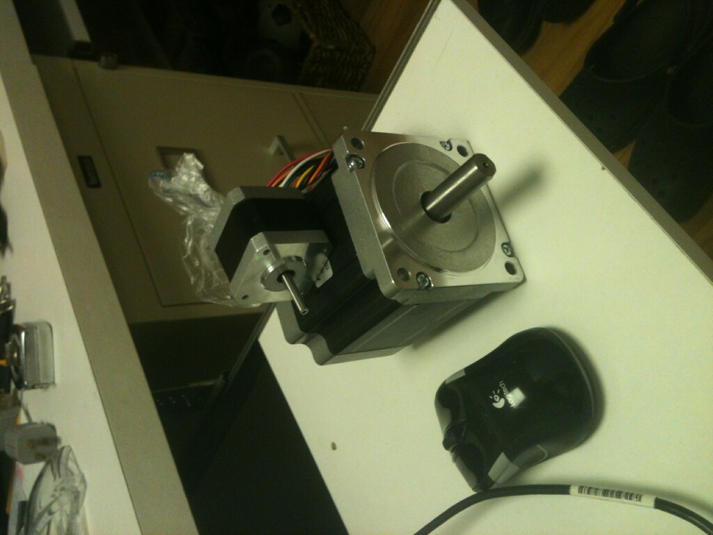
Yesterday I received the MBE extruder I bought. I took the motor out of the package. WOW I had no idea the printers I've been looking at on the forum were so tiny! The attached photo shows what I mean. The one on the bottom is an axis drive motor, the one on top from the extruder.
See what I mean? The Ifactory is only about 500 lbs. Compared to my Bridgeport mill at 2000 lbs, or the CNC knee mill I once owned at 5,000 lbs, or the Fadal 6030 that I used to run at maybe 12,000 lbs the Ifactory is really tiny.
I need to adjust my sense of scale!
Gary H. Lucas
See what I mean? The Ifactory is only about 500 lbs. Compared to my Bridgeport mill at 2000 lbs, or the CNC knee mill I once owned at 5,000 lbs, or the Fadal 6030 that I used to run at maybe 12,000 lbs the Ifactory is really tiny.
I need to adjust my sense of scale!
Gary H. Lucas
|
Some welcome progress February 27, 2013 10:52PM |
Registered: 11 years ago Posts: 205 |
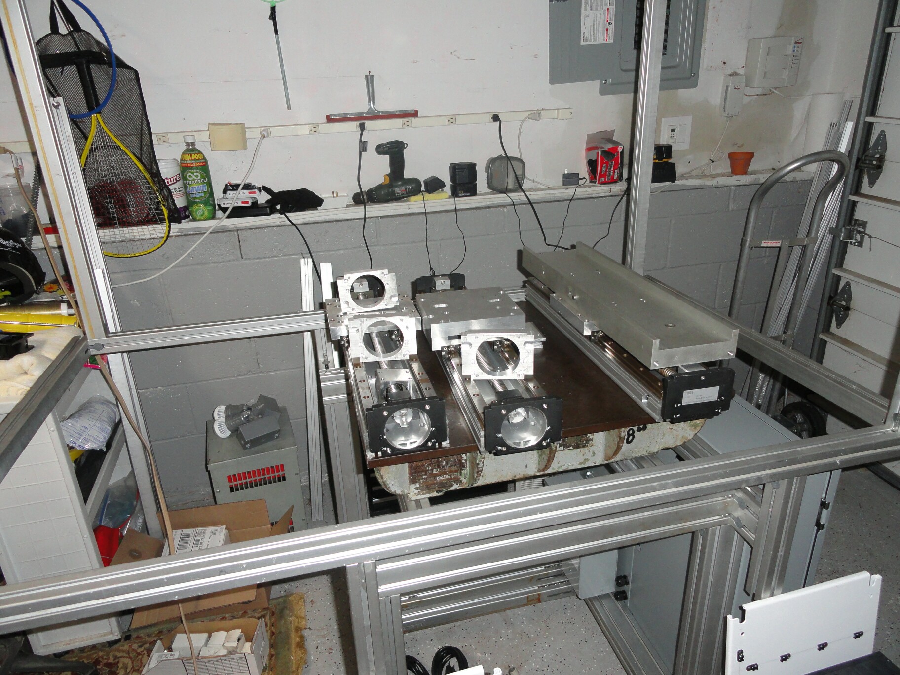
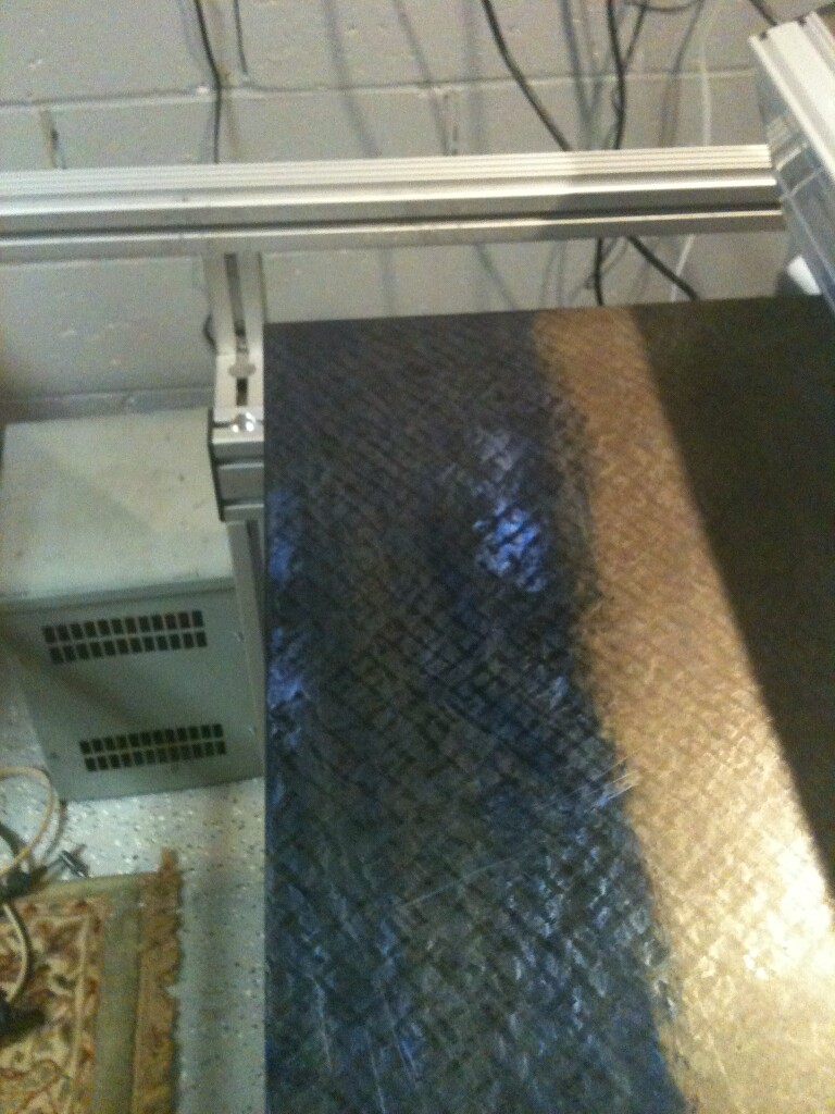
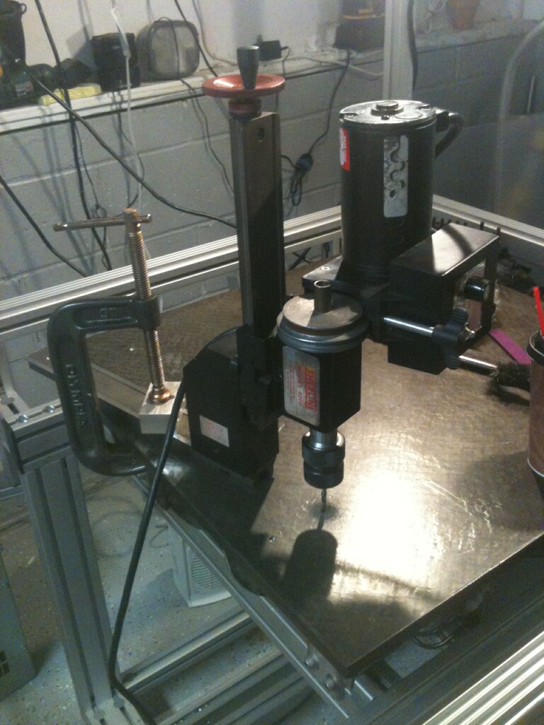
Today I finally bolted down one of the THK linear slides to the cast iron table. When I set it in place I could detect a very slight rocking, indicating the table or the slide was not flat. I took some high spot bluing and coated the table, then set the slide in place. Two tiny high spots showed up. I used a carbide machine tool scraper I've had for many years to scrape down those spots, by a couple of ten thousands of an inch. After about 10 trials the slide fit the table perfectly. So both part are extremely flat and accurate. Good news since the slides were purchased used and the cast iron table is probably fifty year old! I didn't want to warp the slide pulling it flat with the bolts.
I couldn't find or rent a mag drill to do the bolt holes. Then I realized I could us the Sherline mill attachment that I bought. I removed the Sherline lathe bed from it's base and mounted the mill column and spindle on it. then I C-clamped it to the table to drill the holes. It worked well. I also used it to start the tap in straight on each hole.
I also scraped in the adapter plate for the vertical axis, onto the horizontal axis. The adapter and the slide table were very easy to scrape in for a perfect fit. In fact with it lightly clamped in place my tenths dial indicator showed no motion no matter where or how I pushed on it. The top of the adapter is a different story. It has about 2 thousands tilt to one end. Amazing how much scraping it takes to remove that much, even on aluminum!
|
The blues March 04, 2013 08:18PM |
Registered: 11 years ago Posts: 205 |
I finally got to putting the big pieces together. I wanted to mount the X axis THK slide on the cast iron table. I set in location and noted that I could feel an almost imperceptable rocking motion, indicating that the slide didn't exactly match the table. So I got out some bluing and coated the table and slide. I could easily see two small high spots on the table. I have a carbide machine tool way scraper that I've had for years but never actually used for it's intended purpose. So scraped the high spots and tried again. It was clearly better, so I did it over and over again, each time seeing an improvement. It is truly amazing how you can feel the difference, and how slippery the surfaces become when they match perfectly!
So how much metal did I actually remove? Well I have another part where my dial indicator shows a high spot of nearly 0.002". After scraping carefully for about an hour, it is still 0.0005 high! So I suspect I only removed a tenth or two from the cast iron table. DANG that sucker is flat!
I also blued and scraped the interface between the X axis slide and the adapter plate for they Z axis. Again it is amazing how two shiny highly machined surfaces could be noticably improved with a little bluing and scraping! The goal here was to make sure that when I tighten the bolts down holding the adapter that the X slide and bearings don't warp.
The actual fit between the Z axis slide and the adapter plate is a real tough one. The adapter plate isn't flat on top, and my old clapped out Bridgeport would not have improved that surface. The dial indicator shows quite hill in the middle, up to about 0.003". Too make matters worse the vertical axis is in two pieces bolted together, making scraping them in more difficult. Also this connection isn't just two mating surfaces. The axis' actually have to be perfectly square to each other in three directions as well. Get this connection right and I have a nice accurate machine tool. If I don't I've spent a lot of money for a toy.
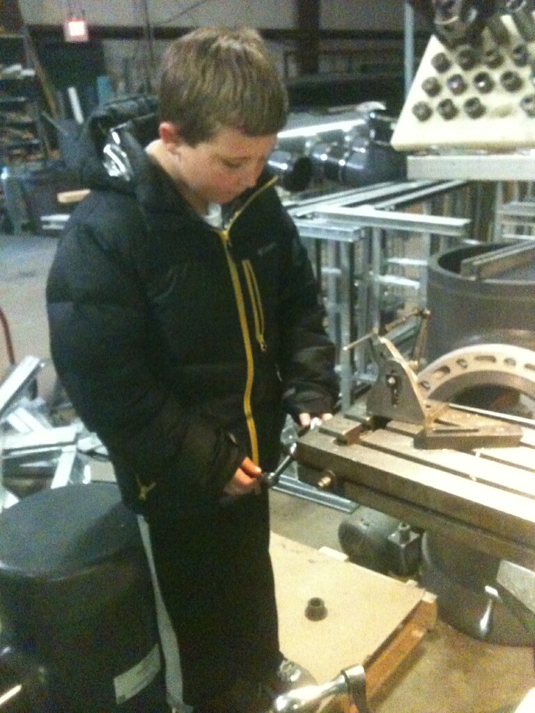
I've hung all the parts together to get some measurements and I took a few pictures of the progress. My grandson spent the day with me at my workplace on Saturday as I made a few more parts. He machined his first slot on the top of a bracket. He also cranked the dials to the locations for all the bolt holes we drilled. He seems to have picked up counting dial rotations and stopping at the right places in both directions just find. He also picked up the concept of the edge finder too. Important basics!
Gary H. Lucas
So how much metal did I actually remove? Well I have another part where my dial indicator shows a high spot of nearly 0.002". After scraping carefully for about an hour, it is still 0.0005 high! So I suspect I only removed a tenth or two from the cast iron table. DANG that sucker is flat!
I also blued and scraped the interface between the X axis slide and the adapter plate for they Z axis. Again it is amazing how two shiny highly machined surfaces could be noticably improved with a little bluing and scraping! The goal here was to make sure that when I tighten the bolts down holding the adapter that the X slide and bearings don't warp.
The actual fit between the Z axis slide and the adapter plate is a real tough one. The adapter plate isn't flat on top, and my old clapped out Bridgeport would not have improved that surface. The dial indicator shows quite hill in the middle, up to about 0.003". Too make matters worse the vertical axis is in two pieces bolted together, making scraping them in more difficult. Also this connection isn't just two mating surfaces. The axis' actually have to be perfectly square to each other in three directions as well. Get this connection right and I have a nice accurate machine tool. If I don't I've spent a lot of money for a toy.
I've hung all the parts together to get some measurements and I took a few pictures of the progress. My grandson spent the day with me at my workplace on Saturday as I made a few more parts. He machined his first slot on the top of a bracket. He also cranked the dials to the locations for all the bolt holes we drilled. He seems to have picked up counting dial rotations and stopping at the right places in both directions just find. He also picked up the concept of the edge finder too. Important basics!
Gary H. Lucas
|
It's ALIVE! May 15, 2013 10:47PM |
Registered: 11 years ago Posts: 205 |
I finally got the Ifactory running! The youtube link should show it cutting holes in a plastic wheel. The program is way less than optimum but it works. I need to do a hundred of these so I'll optimize it a bit.
The motors on all Axis are 800 in/oz running on a 69 volt power supply. Currently have the motors tuned for 4000mm/min. I had them at 6000mm/min and seemed to lose a few steps. Work envelope is 18" x 18" x 18"
[youtu.be]
Gary H. Lucas
The motors on all Axis are 800 in/oz running on a 69 volt power supply. Currently have the motors tuned for 4000mm/min. I had them at 6000mm/min and seemed to lose a few steps. Work envelope is 18" x 18" x 18"
[youtu.be]
Gary H. Lucas
Sorry, only registered users may post in this forum.