Confirming my construction, did I do this right?
Posted by Ohmarinus
|
Confirming my construction, did I do this right? March 30, 2013 02:29PM |
Admin Registered: 11 years ago Posts: 3,096 |
Hi everyone, I have finally put my RepRap Air 2 XL together.
I am totally new to 3D printing, the machine works, extruding works etc, but the endstops don't.
Also I am starting to doubt I might have put my X-axis the wrong way around, or doesn't it matter?
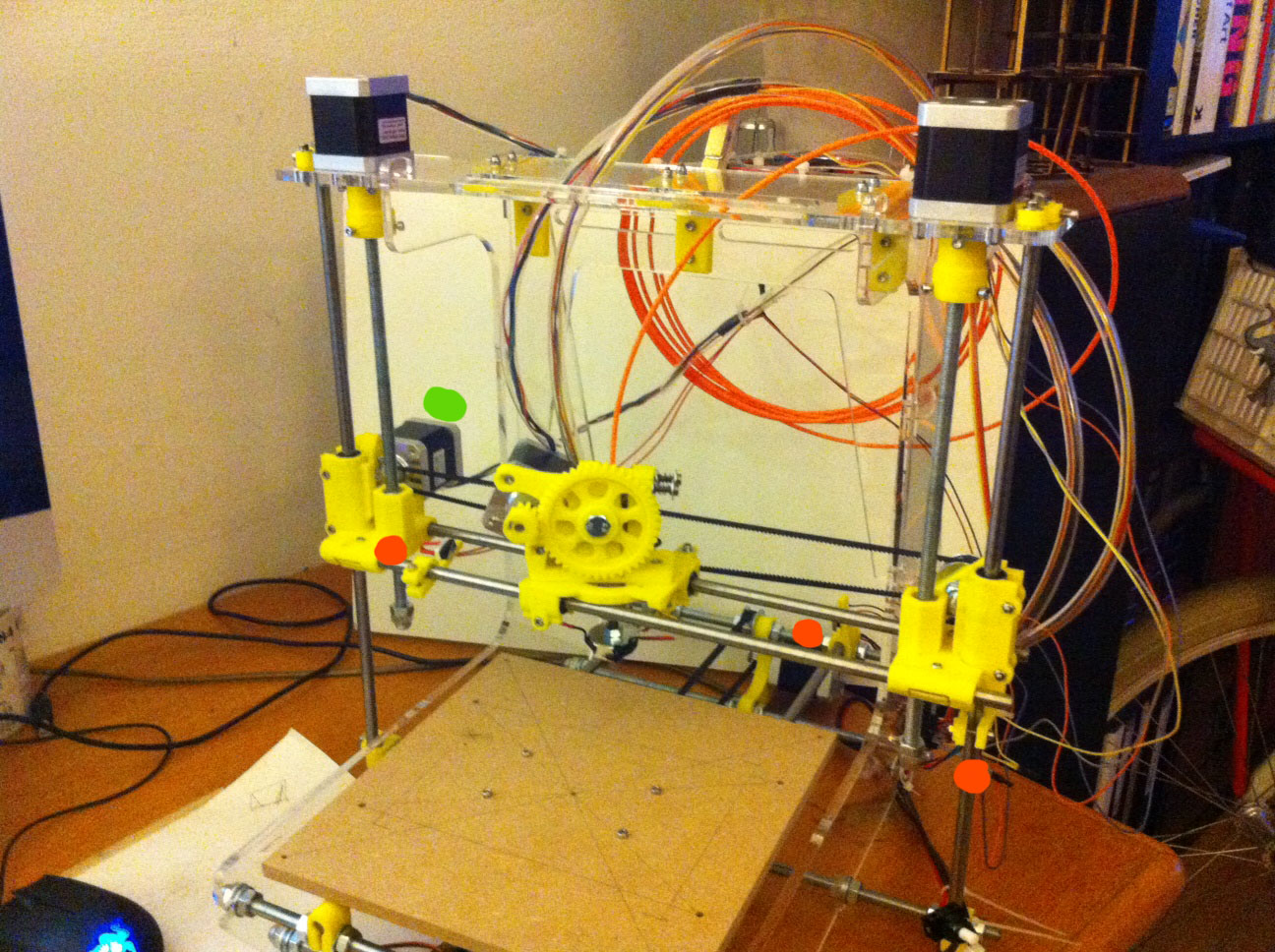
I have highlighted the placements of my endstops (orange) and X-axis stepper motor (green) in the attached picture.
Can it be that the X-axis stepper motor should be on the other side?
Can anyone tell if I did this correctly? And can it be possible I need to turn around polarity for the endstop switches? It is a switch with three pins, I have connected the two wires to the outermost pins of each switch and connected it to the outermost pins on each endstop connector.
Edited 2 time(s). Last edit at 03/30/2013 02:30PM by Ohmarinus.
I am totally new to 3D printing, the machine works, extruding works etc, but the endstops don't.
Also I am starting to doubt I might have put my X-axis the wrong way around, or doesn't it matter?
I have highlighted the placements of my endstops (orange) and X-axis stepper motor (green) in the attached picture.
Can it be that the X-axis stepper motor should be on the other side?
Can anyone tell if I did this correctly? And can it be possible I need to turn around polarity for the endstop switches? It is a switch with three pins, I have connected the two wires to the outermost pins of each switch and connected it to the outermost pins on each endstop connector.
Edited 2 time(s). Last edit at 03/30/2013 02:30PM by Ohmarinus.
|
Re: Confirming my construction, did I do this right? March 30, 2013 02:58PM |
Registered: 11 years ago Posts: 490 |
If you type "M119" into the input field under the text output of Pronterface, you can check your end stop status.
Try sending this without any of the end stops engaged first. Output should be "open" for all three axes (you will get a min. and a max. output for each axis).
Now try pressing one of the end stop switches and type in M119 again (while keeping the switch pressed).
If something has changed about the end stop status - it should read "triggered" now, you know that it is working.
In case nothing changes in the output, your firmware might be configured incorrectly.
Which firmware are you using, by the way?
Edited 1 time(s). Last edit at 03/30/2013 02:59PM by uGen.
|
Re: Confirming my construction, did I do this right? March 30, 2013 03:13PM |
Admin Registered: 11 years ago Posts: 3,096 |
That is a very good question. The seller is very unclear about answering my questions.
.
Since he preloaded it for me and told me it should be fine as it is now... I have no idea exactly.
But he did send me the firmware, but it's just an arduino installer and is also a windows exe, so I can't open that on my mac.
He told me something about: Kliment Sprinter does that ring a bell?
uGen Wrote:
-------------------------------------------------------
> If you type "M119" into the input field under the
> text output of Pronterface, you can check your end
> stop status.
> Try sending this without any of the end stops
> engaged first. Output should be "open" for all
> three axes (you will get a min. and a max. output
> for each axis).
> Now try pressing one of the end stop switches and
> type in M119 again (while keeping the switch
> pressed).
> If something has changed about the end stop status
> - it should read "triggered" now, you know that it
> is working.
> In case nothing changes in the output, your
> firmware might be configured incorrectly.
>
> Which firmware are you using, by the way?
Edited 4 time(s). Last edit at 03/30/2013 03:23PM by Ohmarinus.
|
Re: Confirming my construction, did I do this right? March 30, 2013 03:33PM |
Registered: 11 years ago Posts: 490 |
Argh. That sucks.
Alright, Sprinter sounds familiar, although I personally am using Marlin. After a quick googling, I have found out that the last update to Sprinter was 6 months ago while Marlin is quite up to date. Marlin will also give you better prints because of its look-ahead. Don't know why the vendor put Sprinter on your board...
You can get Arduino for Mac, too: Arduino Download Page
I would recommend installing the Marlin firmware and using the configuration file in order to set up your printer correctly. If your seller does not really answer your questions, you have no way to tell how your end stops are configured in the firmware. So instead of poking around, getting the full picture from seeing and altering the firmware would be more beneficial, I think.
|
Re: Confirming my construction, did I do this right? March 30, 2013 03:46PM |
Admin Registered: 11 years ago Posts: 3,096 |
True true, I already have the arduino program installed because I have an arduino board also, not using it for this printer, but just for playing around.
So, is it a lot of work to install new firmware on a Sanguino? What kind of data do I need to configure the firmware? Since the seller isn't giving out much info I don't have anything like hardware information.
uGen Wrote:
-------------------------------------------------------
> Argh. That sucks.
> Alright, Sprinter sounds familiar, although I
> personally am using Marlin. After a quick
> googling, I have found out that the last update to
> Sprinter was 6 months ago while Marlin is quite up
> to date. Marlin will also give you better prints
> because of its look-ahead. Don't know why the
> vendor put Sprinter on your board...
>
> You can get Arduino for Mac, too: Arduino Download
> Page
> I would recommend installing the Marlin firmware
> and using the configuration file in order to set
> up your printer correctly. If your seller does not
> really answer your questions, you have no way to
> tell how your end stops are configured in the
> firmware. So instead of poking around, getting the
> full picture from seeing and altering the firmware
> would be more beneficial, I think.
|
Re: Confirming my construction, did I do this right? March 30, 2013 03:57PM |
Registered: 11 years ago Posts: 490 |
I don't know the exact procedures of installing the firmware on a Sanguino since the ATMega is not one of the standard Arduino ones. You might have to install some extra bits for your Arduino IDE (which fortunately are in the same Repo as the Marlin firmware). Other than that, uploading the firmware should be the same as uploading an Arduino sketch.
What you need to configure is the steps per mm for all axes, the dimensions, endstop positions (max. or min) and whether to use pull-ups or not and some temperature settings.
All this can be found in the configuration.h file. Most of the stuff is more or less self-explanatory, but the temperature settings might require some experimentation depending on the hot end that you are using. I have found the default settings for the Ultimaker quite useful, though.
Edited 1 time(s). Last edit at 03/30/2013 03:59PM by uGen.
|
Re: Confirming my construction, did I do this right? March 30, 2013 04:32PM |
Admin Registered: 11 years ago Posts: 3,096 |
Great, thanks for your help so far! 
I'm currently wiring up the heatbed also, the seller told me there has to be a relais between the sanguino and the heatbed, or if I didn't use the relais, I would have to hook up the MOSFET with a heatsink. (damn, tested it, there is no way I can hook up the heatsink with the MOSFET)
So I am totally confused about wiring up with the relais, so I have decided to go for a heatsink on the mosfet and not use the relais.
Do I need to add cooling-paste in between the mosfet and the heatsink or can I just screw it on? I had to break off some cooling ribs because the cooler element was too big for the space around the mosfet. And can it be dangerous if the cooling element touches the head of the MOSFET next to it?
It's a Heatbed MKII btw. I will add some thicker gauge wire, like the ones I used on my hotend.
Nevermind, there is just no way of attaching a heatsink to the mosfet. I will start working on the solution by using a Relay.
Will also read some more about the firmware. I have no idea how I know how many steps per mm I want, or whats a normal number!
I also don't know the dimensions, because this machine has a slightly bigger printing area than the normal Reprap Air. Around 200x200x130mm, but I already noticed that the maximum printing area isn't as big as advertised.
- Marinus
uGen Wrote:
-------------------------------------------------------
> I don't know the exact procedures of installing
> the firmware on a Sanguino since the ATMega is not
> one of the standard Arduino ones. You might have
> to install some extra bits for your Arduino IDE
> (which fortunately are in the same Repo as the
> Marlin firmware). Other than that, uploading the
> firmware should be the same as uploading an
> Arduino sketch.
>
> What you need to configure is the steps per mm for
> all axes, the dimensions, endstop positions (max.
> or min) and whether to use pull-ups or not and
> some temperature settings.
> All this can be found in the configuration.h file.
> Most of the stuff is more or less
> self-explanatory, but the temperature settings
> might require some experimentation depending on
> the hot end that you are using. I have found the
> default settings for the Ultimaker quite useful,
> though.
Edited 2 time(s). Last edit at 03/30/2013 05:00PM by Ohmarinus.
|
Re: Confirming my construction, did I do this right? March 30, 2013 07:20PM |
Registered: 11 years ago Posts: 490 |
You are welcome!
Just refreshed my memory of the Sanguinololu. Wow, that space between the MOSFETs really IS tight! I am pretty sure that you can run the MOSFET without heatsink, though. Of the 14 or so RepRaps I have seen in person, none has any heatsink besides on the stepper drivers and they run totally reliably (heated bed wise anyway). Mine is the only one featuring a heatsink for the MOSFET of the heated bed, but it may well be unnecessary. All of these RepRaps use RAMPS boards by the way, but the Sanguinololu is also fine.
The steps per mm is actually pretty easy to calculate: you need the number of teeth on your pulleys and its pitch for X and Y. Assuming that you have T5 belts and a pulley with 12 teeth, that would make 60mm per complete revolution of the pulley (as T5 = 5mm pitch).
Then, you need the steps/revolution of your stepper motor times microstepping level. Let's assume that you have 16x microstepping activated (all 3 jumpers under the stepper drivers are set) and a 200 step/rev. motor, that would make 3200 steps/revolution.
Now divide the distance of travel per revolution with total steps per revolution: 60/3200=0.01875. This is the distance of one step in 16x microstepping.
In order to know how much steps are required for one single mm, divide 1 with the result: 1/0.01875=53.3334.
So you will have 53.3334 steps per mm on your X and Y axes.
Do the same with the Z axis, replacing the belt pitch with the leadscrew pitch. The most common M8 screws have 1.25mm pitch.
To sum it up in a nice equation: Steps/mm = 1mm / ((mm / revolution) / ((steps / revolution) * microstepping))
For example: 53.3334 steps/mm = 1mm / (60mm / (200 steps * 16))
You can derive the overall dimension by measuring where the travel of the axes stop. Better subtract some mm's for safety, though.
|
Re: Confirming my construction, did I do this right? March 30, 2013 09:25PM |
Admin Registered: 11 years ago Posts: 3,096 |
I have finally managed to get everything done
Not yet with all programming, but at least it's running now as it is. I will do the firmware upgrade tomorrow.
Question:
When I start a print, my hotend starts cooling down, and nothing comes out, but the extruder wheel is turning, and when I click extrude manually, that silky thread of ABS just comes out normally, but when I give my printer a print assignment the hotend starts cooling down, and it really has problems staying hot.
Can this be due to not thick-enough wire? In other words, can the wire thickness cause the hotend to malfunction? It really has a hard time going above 210 degrees celsius, it's a terrible wait and when I start extruding, the temperature either drops, or the hotend just shuts down and goes back to around 170~190 degrees celsius and starts heating back up after that.
Update:
After turning off the heatbed, I managed to print a cube, very ugly, and it let go of the print bed because the bottom had cooled down.
My guess is that the PSU doesn't allow enough power to be drawn, so I am thinking of asking the seller if I can get a refund on the shitty PSU he supplied. I will rip out the PSU of my old computer, and try and connect that one to the sanguinololu.
Would that be a good idea?
The PSU has the following ratings:
+5v - 16.4A
+12v - 24A
Can it be this isn't enough?
Edited 1 time(s). Last edit at 03/30/2013 10:18PM by Ohmarinus.
|
Re: Confirming my construction, did I do this right? March 31, 2013 06:45AM |
Registered: 11 years ago Posts: 490 |
24A on the 12V line should be plenty. That makes 12v*24A = 288W (my power supply has 320W and the 32W difference is negligible).
If you are unsure about how much power your hot end gets, you can use a multimeter to measure the current that goes through it. Multiply the value of the current with 12V and you get the power in Watts (like I did up there to get the power output of your PSU). About 20W should be normal for a hot end.
What hot end are you using? Could you post a close-up shot of it?
From what I see on your original photo, there is no fan blowing against the hot end, so it doesn't lose heat by excessive cooling. It should also get enough power from the board. Maybe, the temperature regulation is not set correctly for your hot end?
You can test that out with altering the PID settings: PID settings M-Code
The PID I found useful for my hot end were: P 22.2 I 1.08 D 114
Type the M301 command with these PID values into the console in pronterface and try to heat your hot end up. If anything changed in the way it heats up, the default values are most likely wrong. Caveat: after shutting the printer down, the new PID values will be lost, so you will have to store your new values with M500 in order to make them persistent.
If you have found that the new values do alter the behaviour of the hot end, but are not totally satisfied, SLIGHTLY alter the P value. The higher the P value is, the faster the hot end will attempt to reach the set temperature - if you alter it too much, the heater may overshoot. In the worst case, the overshoot will amplify to both sides (first, heating too much, then letting the hot end cool too much), resulting in wild temperature swings. Try increments of .5 first.
|
Re: Confirming my construction, did I do this right? March 31, 2013 08:20AM |
Admin Registered: 11 years ago Posts: 3,096 |
The voltage on the resistor reads:
9.26 Volt
I think my Multimeter only goes to max 10 Amps? It has a warning on the meter saying '10Amax - Unfused'
I can't find any multimeters that have more than 10 amps measuring capability? Am I doing something wrong?
I checked them all the way up to the 90 euros range, and didn't see any, I can't spend that much on a multimeter now, I already spend all my money on new tools I needed to put the machine together for now.. I guess there is no other way to measure the amperage?
This is the hotend I am using:
[www.printedparts.nl]
Edited 2 time(s). Last edit at 03/31/2013 08:49AM by Ohmarinus.
|
Re: Confirming my construction, did I do this right? March 31, 2013 08:50AM |
Registered: 12 years ago Posts: 46 |
Ohmarinus Wrote:
-------------------------------------------------------
> Hi everyone, I have finally put my RepRap Air 2 XL together
> I have connected the two wires to the
> outermost pins of each switch and connected it to
> the outermost pins on each endstop connector
All the microswitches I have used need to be connected between the centre pin
and one of the outer pins.
Centre and one end pin will be normally open circuit, the other end pin will be normally closed.
It is easy to check, just press the switch lever button and check the pins with a meter to find which is which!
TC
|
Re: Confirming my construction, did I do this right? March 31, 2013 09:12AM |
Admin Registered: 11 years ago Posts: 3,096 |
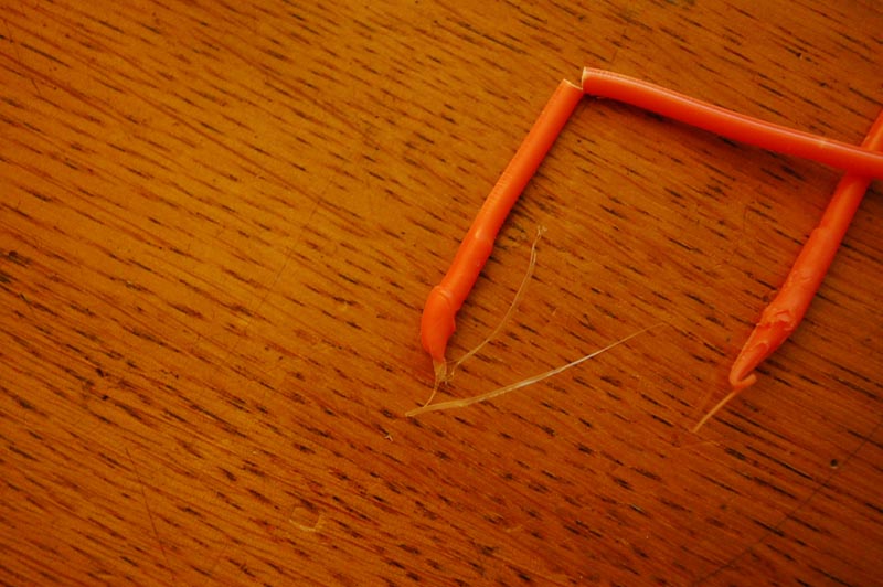
The endstops all work correctly now
I have a picture here of how the filament looks when the extruder jams and I cut off the 'weird' part
[img811.imageshack.us]
I'm really done with this machine now. I know it's not me that is messing it up, I feel like the guy I bought the parts from just tried to make money fast with shitty cheap components.
Also from my last reaction:
The voltage on the resistor reads:
9.26 Volt
I think my Multimeter only goes to max 10 Amps? It has a warning on the meter saying '10Amax - Unfused'
I can't find any multimeters that have more than 10 amps measuring capability? Am I doing something wrong?
I checked them all the way up to the 90 euros range, and didn't see any, I can't spend that much on a multimeter now, I already spend all my money on new tools I needed to put the machine together for now.. I guess there is no other way to measure the amperage?
This is the hotend I am using:
[www.printedparts.nl]
TCase Wrote:
-------------------------------------------------------
> Ohmarinus Wrote:
> --------------------------------------------------
> -----
> > Hi everyone, I have finally put my RepRap Air 2
> XL together
>
> > I have connected the two wires to the
> > outermost pins of each switch and connected it
> to
> > the outermost pins on each endstop connector
>
> All the microswitches I have used need to be
> connected between the centre pin
> and one of the outer pins.
> Centre and one end pin will be normally open
> circuit, the other end pin will be normally
> closed.
> It is easy to check, just press the switch lever
> button and check the pins with a meter to find
> which is which!
>
> TC
Edited 1 time(s). Last edit at 03/31/2013 09:16AM by Ohmarinus.
|
Re: Confirming my construction, did I do this right? March 31, 2013 09:24AM |
Registered: 11 years ago Posts: 490 |
Ah, don't worry. The link to your hot end already gave me the information needed to tell you the power rating for your hot end:
In the product images, the seller labelled the resistor as 6.7 Ohm.
So 12 V / 6.7 Ohm = 1.791 A (remember Ohm's law: E=I*R ?)
1.791 A * 12 V = 21.492 W. Your hot end should be more powerful than mine, heater-wise.
And if you measure < 1.791 A +/- a tolerance of 5% or so, the problem should not be in the wiring.
Normally, the hot ends should not draw more than 3.5 Amps of current max, so you are totally safe with your Multimeter. I wouldn't use it on the heated bed, though as the current may exceed the Multimeter's rating.
|
Re: Confirming my construction, did I do this right? March 31, 2013 09:51AM |
Admin Registered: 11 years ago Posts: 3,096 |
Did you also see the image?
Even when the hotend is well up to temperature, the ABS just gets lodged in the tube before the nozzle.
I will measure again
My readings:
10.5 volts
17/18 amps
After measuring again I get 11 volts, it keeps going up and down.
So I probably just didn't ruin my multimeter it's 17 amps instead of 1.79
I would say 10.5 V * 17 A = 178,5 W
Considering the fact that the filament keeps jamming when it's has been stationary for more than 10 seconds, I am already expecting that to still be a problem when I actually do get the hotend heating up properly..
I am very worried that what you see on the picture, will continue to keep happening.
Wish I had never bought this kit from this seller. Everything has been broken/malfunctioning/poorly printed..
I emailed the seller that I am worried about the filament getting stuck in the nozzle, wish I had bought a Mendel or something, but the seller told me the Air was so much easier for a beginner to assemble. I wonder what his reply will be.
When I have uploaded the new firmware, I hope it is going to work, and will also try a different power supply if it still isn't solved with the new firmware, but I really think that the hotend is not functioning properly, mechanically speaking.
uGen Wrote:
-------------------------------------------------------
> Ah, don't worry. The link to your hot end already
> gave me the information needed to tell you the
> power rating for your hot end:
> In the product images, the seller labelled the
> resistor as 6.7 Ohm.
> So 12 V / 6.7 Ohm = 1.791 A (remember Ohm's law:
> E=I*R ?)
> 1.791 A * 12 V = 21.492 W. Your hot end should be
> more powerful than mine, heater-wise.
> And if you measure < 1.791 A +/- a tolerance of 5%
> or so, the problem should not be in the wiring.
> Normally, the hot ends should not draw more than
> 3.5 Amps of current max, so you are totally safe
> with your Multimeter. I wouldn't use it on the
> heated bed, though as the current may exceed the
> Multimeter's rating.
Edited 1 time(s). Last edit at 03/31/2013 10:02AM by Ohmarinus.
Even when the hotend is well up to temperature, the ABS just gets lodged in the tube before the nozzle.
I will measure again
My readings:
10.5 volts
17/18 amps
After measuring again I get 11 volts, it keeps going up and down.
So I probably just didn't ruin my multimeter
it's 17 amps instead of 1.79I would say 10.5 V * 17 A = 178,5 W
Considering the fact that the filament keeps jamming when it's has been stationary for more than 10 seconds, I am already expecting that to still be a problem when I actually do get the hotend heating up properly..
I am very worried that what you see on the picture, will continue to keep happening.
Wish I had never bought this kit from this seller. Everything has been broken/malfunctioning/poorly printed..
I emailed the seller that I am worried about the filament getting stuck in the nozzle, wish I had bought a Mendel or something, but the seller told me the Air was so much easier for a beginner to assemble. I wonder what his reply will be.
When I have uploaded the new firmware, I hope it is going to work, and will also try a different power supply if it still isn't solved with the new firmware, but I really think that the hotend is not functioning properly, mechanically speaking.
uGen Wrote:
-------------------------------------------------------
> Ah, don't worry. The link to your hot end already
> gave me the information needed to tell you the
> power rating for your hot end:
> In the product images, the seller labelled the
> resistor as 6.7 Ohm.
> So 12 V / 6.7 Ohm = 1.791 A (remember Ohm's law:
> E=I*R ?)
> 1.791 A * 12 V = 21.492 W. Your hot end should be
> more powerful than mine, heater-wise.
> And if you measure < 1.791 A +/- a tolerance of 5%
> or so, the problem should not be in the wiring.
> Normally, the hot ends should not draw more than
> 3.5 Amps of current max, so you are totally safe
> with your Multimeter. I wouldn't use it on the
> heated bed, though as the current may exceed the
> Multimeter's rating.
Edited 1 time(s). Last edit at 03/31/2013 10:02AM by Ohmarinus.
|
Re: Confirming my construction, did I do this right? March 31, 2013 10:14AM |
Registered: 11 years ago Posts: 490 |
Wait a minute, there is no way that the hot end is drawing 17 amps unless it is shorted out!
Please measure the resistance between the leads of the resistor just to make sure this isn't the case, but it is rather strange that you measured the current to be quite precisely 10 times more than it should be...
Didn't see the image before...sorry, I cannot tell what may be causing the jams. I simply did not have many jams at all to be able to exactly analyse this. But if you are having jams constantly, it might be better to switch the hot end.
|
Re: Confirming my construction, did I do this right? March 31, 2013 10:23AM |
Admin Registered: 11 years ago Posts: 3,096 |
The resistance on the resistor is 7.1 or 7.2 Ohms.
To be honest I don't know what to do anymore.
I will ask the seller for a new hotend, this is getting out of hand.
I also have a backup resistor btw, that measures: 7.2 Ohms.
uGen Wrote:
-------------------------------------------------------
> Wait a minute, there is no way that the hot end is
> drawing 17 amps unless it is shorted out!
> Please measure the resistance between the leads of
> the resistor just to make sure this isn't the
> case, but it is rather strange that you measured
> the current to be quite precisely 10 times more
> than it should be...
>
> Didn't see the image before...sorry, I cannot tell
> what may be causing the jams. I simply did not
> have many jams at all to be able to exactly
> analyse this. But if you are having jams
> constantly, it might be better to switch the hot
> end.
|
Re: Confirming my construction, did I do this right? March 31, 2013 10:38AM |
Registered: 11 years ago Posts: 490 |
|
Re: Confirming my construction, did I do this right? March 31, 2013 10:39AM |
Admin Registered: 11 years ago Posts: 3,096 |
I set up my Multimeter to measure on the left and right side of the resistor..
Did my multimeter short it out?
I connected it parallel I guess.
Should it be in serial?
Hey good you asked, it is 1.6 amps!
Damn.. How could I be so wrong...
uGen Wrote:
-------------------------------------------------------
> That is strange. With 7.1 - 7.2 Ohms there is just
> no way to get 17 Amps at 10-12 Volts. The max.
> possible amperage would be 12V / 7.1Ohms = 1.69
> Amps.
> Electrically, your hot end should be correct.
> Where did you put the probes to measure this high
> current?
Edited 2 time(s). Last edit at 03/31/2013 10:45AM by Ohmarinus.
|
Re: Confirming my construction, did I do this right? March 31, 2013 10:44AM |
Registered: 11 years ago Posts: 490 |
|
Re: Confirming my construction, did I do this right? March 31, 2013 10:47AM |
Admin Registered: 11 years ago Posts: 3,096 |
1.6 amps
Damn... My bad.
You see, this really is the first time I'm working with things like this. However I did do this a lot as a kid, but I forgot almost everything. But I still kept my multimeter and soldering iron and all my other equipment, for which I am very lucky since I need it all here.
10.5 V * 1.6 A = 16,8 W? (out of my head)
uGen Wrote:
-------------------------------------------------------
> Ah, yes, that is the problem: To measure voltages,
> connecting in parallel is the right way. But to
> measure current, you have to connect your
> multimeter in serial.
Edited 1 time(s). Last edit at 03/31/2013 11:11AM by Ohmarinus.
|
Re: Confirming my construction, did I do this right? March 31, 2013 11:36AM |
Registered: 11 years ago Posts: 490 |
Good, at least your hot end will not cause fires or so.
Still, jamming all the time should not happen with a good hot end. Sometimes, it is the construction that is wrong and the only thing you can do is to use another hot end. So maybe it is better to ask for a refund and order a hot end from another manufacturer?
I learned all this more or less in the past two years...but my memory also glitches from time to time, making me screw up
|
Re: Confirming my construction, did I do this right? March 31, 2013 11:41AM |
Admin Registered: 11 years ago Posts: 3,096 |
Thing is that I bought a complete kit, so refund will not work.
What I can do is ask him to send a new hot end. I will also just open up my hotend to see if I can find out if there is something wrong on the inside, or is a hotend very special?..
Tomorrow I have planned to do firmware again, for I am almost sure the problem cannot be in the hardware for the slow heating. It takes half an hour to go from 190 celsius to 230.
For the jamming hotend.. I will see if I can open it up and discover any kind of weird construction error.
Also, I will take better pictures of the machine.
Thanks for all your replies, without you I would've thought it was all my own fault!
uGen Wrote:
-------------------------------------------------------
> Good, at least your hot end will not cause fires
> or so.
> Still, jamming all the time should not happen with
> a good hot end. Sometimes, it is the construction
> that is wrong and the only thing you can do is to
> use another hot end. So maybe it is better to ask
> for a refund and order a hot end from another
> manufacturer?
>
> I learned all this more or less in the past two
> years...but my memory also glitches from time to
> time, making me screw up
|
Re: Confirming my construction, did I do this right? March 31, 2013 03:33PM |
Registered: 14 years ago Posts: 142 |
uGen Wrote:
-------------------------------------------------------
> Just refreshed my memory of the Sanguinololu. Wow,
> that space between the MOSFETs really IS tight! I
> am pretty sure that you can run the MOSFET without
> heatsink, though. Of the 14 or so RepRaps I have
> seen in person, none has any heatsink besides on
> the stepper drivers and they run totally reliably
> (heated bed wise anyway). Mine is the only one
> featuring a heatsink for the MOSFET of the heated
> bed, but it may well be unnecessary. All of these
> RepRaps use RAMPS boards by the way, but the
> Sanguinololu is also fine.
Hey guys, uGen, great work on helping this guy out. Just anote about the Mosfet and Sanguinololu. I use a Sanguinololu which works just fine, but did have trouble with the wiring overheating. The issue isn't the Mosfet so much as the poor choice of connectors and small traces on the board. See my blog for pictures of how I sorted this based on advise from nophead. (http://blogger.kritzinger.net/2012/04/hot-bed-heat-up-resolution.html)
Basically, run the positive lead direct from your PSU to the heated bed and then run the earth from the tab of the mosfet. This bypasses the small traces and also helps with the heat conductivity as you have a crimp terminal and decent (13A) wire running from the tab.
Good luck.
Craig
|
Re: Confirming my construction, did I do this right? March 31, 2013 04:52PM |
Registered: 11 years ago Posts: 490 |
You are welcome!
The construction of a hot end is pretty basic. It more or less consists of a simple tube (most often lined with PTFE) and ends in the brass nozzle. The only thing you have to be careful about is the small bore of the nozzle. Banging it against a hard surface might damage the nozzle.
Here is a cross-section of a hot end.
What environment are you printing in? Drafts have an enormous effect on the heating capabilities. Even if you are not feeling any wind, there might be a slight draft. You can try to shield the printer with large sheets of paper first and see whether the nozzle heats up faster.
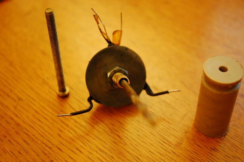
There is also the possibility that thermal conduction between the resistor and the rest of the heat block is bad, but that is hard to see on the product images of your seller because one really has to see how the resistor fits into the hole of the heat block. One thing striking me as odd, though, is the washer sitting atop of the heat block. I can imagine it acting as a massive heat sink, sapping away energy from the nozzle.
Also, I remembered a feature that might help you: M303 (PID autotune). It should be available on Sprinter and lets the machine set the correct PID values. I cannot help you with that, though because I have never used this feature myself.
The construction of a hot end is pretty basic. It more or less consists of a simple tube (most often lined with PTFE) and ends in the brass nozzle. The only thing you have to be careful about is the small bore of the nozzle. Banging it against a hard surface might damage the nozzle.
Here is a cross-section of a hot end.
What environment are you printing in? Drafts have an enormous effect on the heating capabilities. Even if you are not feeling any wind, there might be a slight draft. You can try to shield the printer with large sheets of paper first and see whether the nozzle heats up faster.
There is also the possibility that thermal conduction between the resistor and the rest of the heat block is bad, but that is hard to see on the product images of your seller because one really has to see how the resistor fits into the hole of the heat block. One thing striking me as odd, though, is the washer sitting atop of the heat block. I can imagine it acting as a massive heat sink, sapping away energy from the nozzle.
Also, I remembered a feature that might help you: M303 (PID autotune). It should be available on Sprinter and lets the machine set the correct PID values. I cannot help you with that, though because I have never used this feature myself.
|
Re: Confirming my construction, did I do this right? March 31, 2013 09:05PM |
Admin Registered: 11 years ago Posts: 3,096 |
Since I can't print with this shitty hotend anyway I will open it up and try to see if I can find something wrong with it.
Also, the resistor is very loose inside the aluminium block, I will add a piece of aluminium foil around the resistor to make is a tighter fit if it is possible and I will also try to fabricate an insulation 'housing' around the hotend that first of all protects my extruder from the heat it expels, but also encases the hotend in such a way that the heat is contained around the hotend.
I expect this might help also in case of draft. There is indeed a little bit of draft, I am just in the middle of the livingroom, and will try to add something that keeps the draft contained if possible
Thanks for that tip.
Oh and by the way I think M303 is only a Marlin command, and nog a Kliment Sprinter command. So I will have to look into it tomorrow
Now time for bed!
Happy Easter guys!
- Marinus
Ps. Is it normal that ABS comes out of the hotend when it's heating up? Because wires of ABS come out while it gets around 200 degrees celsius, and I have the idea that it is part of the problem.
uGen Wrote:
-------------------------------------------------------
> You are welcome!
>
> The construction of a hot end is pretty basic. It
> more or less consists of a simple tube (most often
> lined with PTFE) and ends in the brass nozzle. The
> only thing you have to be careful about is the
> small bore of the nozzle. Banging it against a
> hard surface might damage the nozzle.
> Here is a cross-section of a hot end.
>
> What environment are you printing in? Drafts have
> an enormous effect on the heating capabilities.
> Even if you are not feeling any wind, there might
> be a slight draft. You can try to shield the
> printer with large sheets of paper first and see
> whether the nozzle heats up faster.
> There is also the possibility that thermal
> conduction between the resistor and the rest of
> the heat block is bad, but that is hard to see on
> the product images of your seller because one
> really has to see how the resistor fits into the
> hole of the heat block. One thing striking me as
> odd, though, is the washer sitting atop of the
> heat block. I can imagine it acting as a massive
> heat sink, sapping away energy from the nozzle.
>
> Also, I remembered a feature that might help you:
> M303 (PID autotune). It should be available on
> Sprinter and lets the machine set the correct PID
> values. I cannot help you with that, though
> because I have never used this feature myself.
Edited 3 time(s). Last edit at 04/01/2013 06:08PM by Ohmarinus.
|
Re: Confirming my construction, did I do this right? April 01, 2013 07:20AM |
Registered: 11 years ago Posts: 490 |
Strands of ABS coming out is normal. The plastic expands when heated like other materials and thus pushes out a little bit. And if you have a certain feature (I think its name was "Extruder Runout Prevention" or something) enabled, the printer will automatically extrude a little bit every few minutes to prevent the ABS in the nozzle from being overheated and cooked off.
I searched a bit whether the M303 command is available in Sprinter and this commit seems to confirm its availability.
Ok, no wonder you are not getting up to temperature if the resistor doesn't have nice contact with the heat block. Adding aluminium foil is a good idea.
I searched a bit whether the M303 command is available in Sprinter and this commit seems to confirm its availability.
Ok, no wonder you are not getting up to temperature if the resistor doesn't have nice contact with the heat block. Adding aluminium foil is a good idea.
|
Re: Confirming my construction, did I do this right? April 01, 2013 08:14AM |
Admin Registered: 11 years ago Posts: 3,096 |
Okay, thanks for your reply, I have found my old computer in a closet and it has a nice ATX power supply.
Would it be hard to convert my Sanguino to have another connector so I can use my ATX power supply?
Right now it uses this one:
[www.ebay.co.uk]
I don't know why, but it feels better to use an ATX PSU. Also because in the Marlin config I -HAVE- to choose either:
// 1 = ATX
// 2 = X-Box 360 203Watts (the blue wire connected to PS_ON and the red wire to VCC)
What does ABS cook-off mean? Does that mean the ABS gets hard in the tube because the solvents in the ABS vaporize?
I will try to make it really a tight fit, the resistor can be wiggled a bit, but is held in place by a thick layer of some kind of black goo as you can see on the picture of the hotend posted earlier.
And a next topic question:
If I would film anything about this machine, what kind of film footage would you like to see?
- Marinus
uGen Wrote:
-------------------------------------------------------
> Strands of ABS coming out is normal. The plastic
> expands when heated like other materials and thus
> pushes out a little bit. And if you have a certain
> feature (I think its name was "Extruder Runout
> Prevention" or something) enabled, the printer
> will automatically extrude a little bit every few
> minutes to prevent the ABS in the nozzle from
> being overheated and cooked off.
>
> I searched a bit whether the M303 command is
> available in Sprinter and this commit seems to
> confirm its availability.
>
> Ok, no wonder you are not getting up to
> temperature if the resistor doesn't have nice
> contact with the heat block. Adding aluminium foil
> is a good idea.
Edited 1 time(s). Last edit at 04/01/2013 08:19AM by Ohmarinus.
|
Re: Confirming my construction, did I do this right? April 01, 2013 05:49PM |
Registered: 11 years ago Posts: 490 |
Theoretically, it should be possible to de-solder the connector and put a Molex one into its place. Reference the always helpful RepRap Wiki for this.
I am using an industrial power supply and have set Marlin for ATX. This setting is only useful if you want to switch your power supply on and off via G-Code. As I have a switch on my printer, I ignored this setting.
It should not matter what kind of power supply you are using as long as its power output is sufficient and stable. These kinds of industrial power supplies (actual model I am using) are also popular in the community and come with the added benefit of not having too many wires flying around.
ABS cook-off is when the plastic gets heated for too long and degrades. Natural ABS turns yellow-ish and eventually gets charred (the black crud on a lot of hot ends is most likely charred ABS that did not get removed quick enough). This might lead to nasty fumes, jams and bad extrusion quality.
To be honest, one thing about RepRap videos that I am quite tired of seeing is just the hot end printing stuff for like 2 minutes, without any comments. Good videos should be more informative and less monotonous.
Giving an overview over the topic, then cutting to a segment of the printer printing (or whatever you want to show in the particular video), maybe with added explanations and comments and tying it up at the end with a conclusion would be an enjoyable and entertaining format for example.
Oh, and a tripod or camera stand is a nice addition. There are just too many shaky videos with bad sound quality (fingers covering the microphone, constant rustling from moving the camera around in the hand).
I am a little bit discerning and fussy about this topic, I guess...
|
Re: Confirming my construction, did I do this right? April 01, 2013 06:13PM |
Admin Registered: 11 years ago Posts: 3,096 |
Okay I did the autotune for now, I will stick with my current PSU, all I need to know whether I have to set my power supply type in Marlin to 1 or 2 with my current PSU. I guess it should also be 1, so I will try that.
The results of the autotune (shortened it a bit):
Results of the autotune:
Compared to my old PID settings:
So I guess I should set
P = 2860
I = 21
D = 31311
Is this a correct interpretation?
Oh and by the way, the nozzle is screwed SO hard onto the filament tube that I can't unscrew it.. Crap hotend. And hotends are expensive. I will look for guides of making your own hotend.
Anyway, doesn't matter, I have removed the PTFE tube from the hotend and I found what I expected. The diameter of the metal tube that screws into the PTFE is much wider, this is causing expansion of the molten ABS and forms a place where molten ABS collects into a wider part. You can see this as a tiny reservoir, now I have a theory about the ABS clogging up there, here it comes:
- Reservoir fills with molten ABS
- Top of reservoir touches the PTFE tube on the end where the metal tube ends
- Top layer of reservoir cools down too much and the expanded filament wedges itself in the metal tube
Also, the metal tube that screws into the PTFE tube wasn't screwed in all the way, so a little ABS collected on the top edge of the metal tube and this might have adhered to the filament when it was inserted. I will make a schematic drawing of the situation.
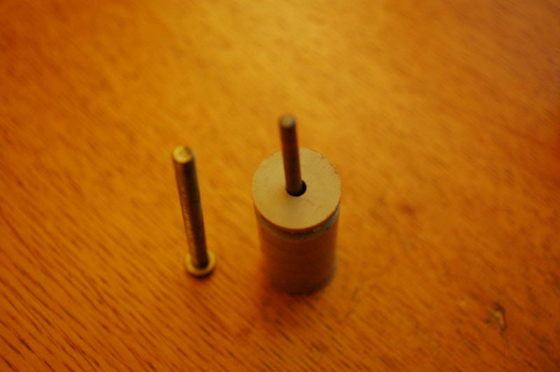
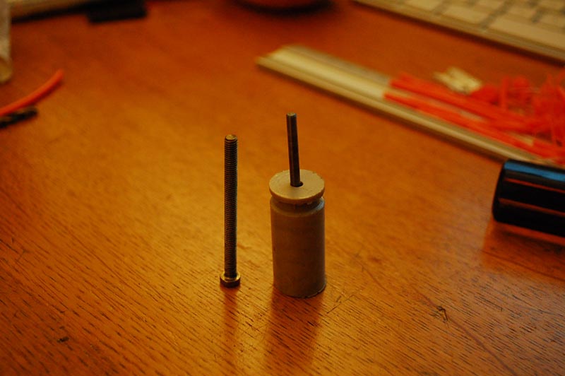
Pictures attached.
What you see on the pictures is the PTFE tube with a 3mm drill bit inserted so you can see the oversize. Next to that is the metal tube, where you can clearly see it's even wider and finally 4th picture, the effect it has on the molten ABS. The ABS is pulled out when the hotend was still hot, so it has been thinned by pulling it through the less-wide PTFE tube.
I have emailed the seller about the bad quality of the hotend and asked if he ever received complaints, and that I will try to make my own hotend. We have a metal workplace in my Art Academy where I study so I might be able to make my own hotend there. We have all kinds of machinery there with which I can turn my own metal parts, add thread to pipes, etcetera. All I have to get is an aluminium block from where I can cut and drill my own hotend design.
The first hotend will be a freestyle, kind of 'guess-O-matic' way of working, just by looking at other hotends. I might even make my own nozzle. I have noticed the nozzle that I got on this hotend doesn't even have the hole in the middle of the nozzle. What a piece of shoosh...
- Marinus
Edited 8 time(s). Last edit at 04/01/2013 08:16PM by Ohmarinus.
The results of the autotune (shortened it a bit):
Results of the autotune:
Connecting...

Sprinter
1.3.22T / 20.08.2012
start
Printer is now online.
SD Start
SD init fail
Soft PWM Init
Planner Init
Stepper Timer init
Free Ram: 455
Plan Buffer Size:1152 / 16
>>>M303
SENDING:M303
PID Autotune start
ok T:21.10 @:255
ok T:22.00 @:255
ok T:23.00 @:255
-
ok T:148.00 @:254
ok T:148.00 @:254
ok T:149.00 @:254
-
ok T:152.00 @:0
ok T:152.00 @:0
ok T:152.00 @:0
ok T:151.00 @:0
 bias: 137 d: 117 min: 147.00 max: 152.10
ok T:149.50 @:254
ok T:148.00 @:254
-
ok T:151.00 @:20
ok T:150.00 @:20
 bias: 138 d: 116 min: 147.00 max: 153.00
ok T:148.70 @:254
ok T:148.00 @:254
ok T:148.00 @:254
ok T:148.00 @:254
-
ok T:151.50 @:22
ok T:151.00 @:22
ok T:150.00 @:22
 bias: 138 d: 116 min: 148.00 max: 152.00
 Ku: 36.92 Tu: 72.76
 Clasic PID
 CFG Kp: 5671
 CFG Ki: 77
 CFG Kd: 25790
 Some overshoot
 CFG Kp: 2835
 CFG Ki: 19
 CFG Kd: 34387
ok T:149.00 @:254
ok T:148.00 @:254
ok T:148.00 @:254
-
ok T:152.00 @:22
ok T:152.00 @:22
ok T:150.40 @:22
 bias: 132 d: 122 min: 148.00 max: 152.30
 Ku: 36.12 Tu: 72.76
 Clasic PID
 CFG Kp: 5548
 CFG Ki: 76
 CFG Kd: 25232
 Some overshoot
 CFG Kp: 2774
 CFG Ki: 19
 CFG Kd: 33642
ok T:149.00 @:254
ok T:148.00 @:254
ok T:148.00 @:254
-
ok T:152.00 @:10
ok T:151.90 @:10
ok T:150.00 @:10
 bias: 137 d: 117 min: 148.00 max: 152.00
 Ku: 37.24 Tu: 65.68
 Clasic PID
 CFG Kp: 5720
 CFG Ki: 87
 CFG Kd: 23483
 Some overshoot
 CFG Kp: 2860
 CFG Ki: 21
 CFG Kd: 31311
PID Autotune finished ! Place the Kp, Ki and Kd constants in the configuration.h
Compared to my old PID settings:
//PID Controler Settings
#define PID_INTEGRAL_DRIVE_MAX 80 // too big, and heater will lag after changing temperature, too small and it might not compensate enough for long-term errors
#define PID_PGAIN 2560 //256 is 1.0  // value of X means that error of 1 degree is changing PWM duty by X, probably no need to go over 25
#define PID_IGAIN 64 //256 is 1.0  // value of X (e.g 0.25) means that each degree error over 1 sec (2 measurements) changes duty cycle by 2X (=0.5) units (verify?)
#define PID_DGAIN 4096 //256 is 1.0  // value of X means that around reached setpoint, each degree change over one measurement (half second) adjusts PWM by X units to compensate
So I guess I should set
P = 2860
I = 21
D = 31311
Is this a correct interpretation?
Oh and by the way, the nozzle is screwed SO hard onto the filament tube that I can't unscrew it.. Crap hotend. And hotends are expensive. I will look for guides of making your own hotend.
Anyway, doesn't matter, I have removed the PTFE tube from the hotend and I found what I expected. The diameter of the metal tube that screws into the PTFE is much wider, this is causing expansion of the molten ABS and forms a place where molten ABS collects into a wider part. You can see this as a tiny reservoir, now I have a theory about the ABS clogging up there, here it comes:
- Reservoir fills with molten ABS
- Top of reservoir touches the PTFE tube on the end where the metal tube ends
- Top layer of reservoir cools down too much and the expanded filament wedges itself in the metal tube
Also, the metal tube that screws into the PTFE tube wasn't screwed in all the way, so a little ABS collected on the top edge of the metal tube and this might have adhered to the filament when it was inserted. I will make a schematic drawing of the situation.
Pictures attached.
What you see on the pictures is the PTFE tube with a 3mm drill bit inserted so you can see the oversize. Next to that is the metal tube, where you can clearly see it's even wider and finally 4th picture, the effect it has on the molten ABS. The ABS is pulled out when the hotend was still hot, so it has been thinned by pulling it through the less-wide PTFE tube.
I have emailed the seller about the bad quality of the hotend and asked if he ever received complaints, and that I will try to make my own hotend. We have a metal workplace in my Art Academy where I study so I might be able to make my own hotend there. We have all kinds of machinery there with which I can turn my own metal parts, add thread to pipes, etcetera. All I have to get is an aluminium block from where I can cut and drill my own hotend design.
The first hotend will be a freestyle, kind of 'guess-O-matic' way of working, just by looking at other hotends. I might even make my own nozzle. I have noticed the nozzle that I got on this hotend doesn't even have the hole in the middle of the nozzle. What a piece of shoosh...
- Marinus
Edited 8 time(s). Last edit at 04/01/2013 08:16PM by Ohmarinus.

Sorry, only registered users may post in this forum.