Nozzle internal geometry
Posted by leadinglights
|
Nozzle internal geometry October 31, 2013 08:34AM |
Registered: 12 years ago Posts: 1,450 |
Is there any data available on the optimum internal geometry for a nozzle? I am particularly interested in getting a small nozzle size at the moment, although any other effects of geometry would also be interesting.
Further info. I have found that my own nozzles are erratic, sometimes giving really good results, sometimes unacceptably bad, so I am trying to tease out the problems with my basic design. So far I have found a likely improvement by using graphite loaded PEEK to line the upper part of the nozzle and to define an inverted taper entry to the melt chamber. (discussion in [forums.reprap.org] ) This looks good but I get unexpected results - two identical nozzles with very different percieved filament feed pressure, or 0.45 and 0.35mm nozzles having similar back pressure. One suspect is in the internal geometry of the entry to the orifice. As my nozzles are drilled in a solid 50mm long 6mm dia stainless steel bar there is a degree of unrepeatability at the output end.
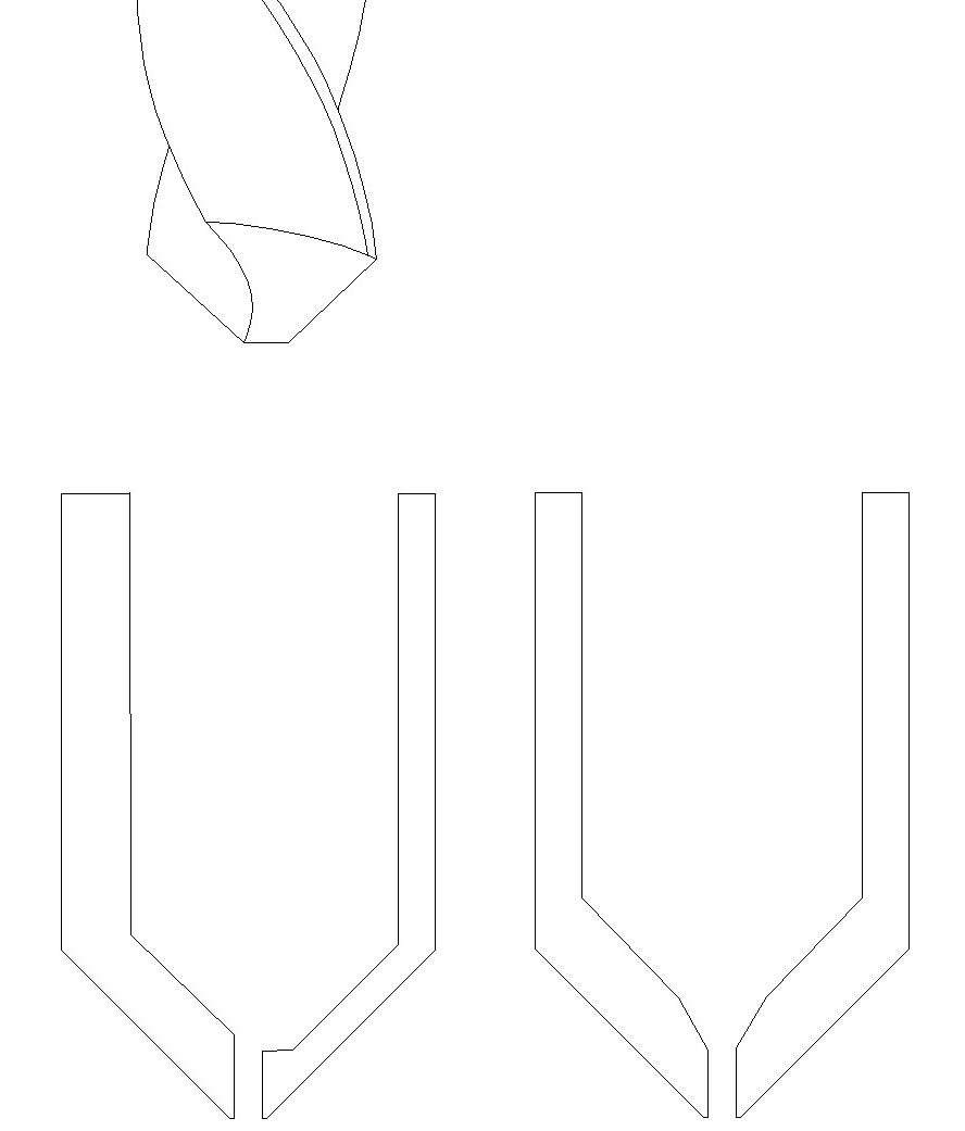
If you look at picture you will see that, if the bottom of the drill wanders off (which it typically does to the tune of about 0.5mm) then drilling either from the outside or the inside will create a lip around the entry to the orifice. Drawing of a drill bit shows the chizel end which gives rise to a flat at the tip of the larger hole. Drawing at the right to show what I expect to be be optimum.
The need for data is because it is proving difficult to drill the final small hole from the inside - 3 0.35mm drill bits silver soldered to 2mm drill stock and 3 failures - a lot of work. Drilling from the outside is easy and doesn't break drills.
Mike
Edited 1 time(s). Last edit at 10/31/2013 11:39AM by leadinglights.
|
Re: Nozzle internal geometry October 31, 2013 12:48PM |
Registered: 10 years ago Posts: 95 |
Perhaps you could get a second similar drill bit and grind the tip to a point for finishing the hole?
Would it be practical to make a screw-on tip that was shallow enough to be able to control the drilling more carefully. Would a softer material such as brass or mild steel be practical?
I assume the attraction of stainless steel is its lower heat conductivity.
...R
Would it be practical to make a screw-on tip that was shallow enough to be able to control the drilling more carefully. Would a softer material such as brass or mild steel be practical?
I assume the attraction of stainless steel is its lower heat conductivity.
...R
|
Re: Nozzle internal geometry October 31, 2013 01:34PM |
Registered: 10 years ago Posts: 1,381 |
Grind the ridge/step out.
Use a silicon carbide grinding bit with a spire shaped tip.
You will need to find one with an extra long shaft.
Or hammer into small pieces a grinding wheel, toss it into the hole, add oil, and use a brass dowel to grind the ridge/step down.
The shape of the brass rod end dictates the form that you will be grinding into the barrel.
Starting point: The length of the orifice land is equal to the hole diameter.
Example: Dia 0.5 mm = 0.5 mm land length.
It's fairly short for the home shop to make the land accurately.
Just a guess, but I doubt any hot end sold comes close.
I was reading about this the other day for extrusion dies, and here is a patent mentioning the same thing.
" land defining orifice 2 may be present between the die face and the converging surface in order to minimize orifice wear. As this land is increased, so does back pressure. Consequently, as small a land as possible should be used in carrying out the process of this invention. Exemplary of the amount of land that can be used is land up to 20 mils wide (distance between die face at orifice and converging surface at orifice) which gives an orifice of corresponding length. "
[www.google.com]
I'm going to guess that most don't have a means of controlling or measuring the land length.
I would grind it by eye until it looked really thin
... and don't drop it.
A2
Edited 2 time(s). Last edit at 10/31/2013 03:51PM by A2.
|
Re: Nozzle internal geometry October 31, 2013 02:59PM |
Registered: 11 years ago Posts: 265 |
How small of a hole can a laser cutter achieve?
Can you give it a single blast to create a .35 mm hole?
Edited 1 time(s). Last edit at 10/31/2013 03:02PM by ShadowRam.
Can you give it a single blast to create a .35 mm hole?
Quote
The laser burns away a portion of material when it cuts through. This is known as the laser kerf and ranges from 0.08mm – 0.45mm depending on the material type and other conditional factors
Edited 1 time(s). Last edit at 10/31/2013 03:02PM by ShadowRam.
|
Re: Nozzle internal geometry October 31, 2013 04:50PM |
Registered: 12 years ago Posts: 1,450 |
@Robin2
I decided to give your suggestion of the 2nd drill bit shaped for the lead up to the small hole. I was able to modify a drill - including cutting the web between the flutes to almost nothing. It doesn't drill very well, but it only has to finish off the hole and looks O.K. when used on a bit of mild steel.
@A2
My best guess is the word "land" applies to how long the orifice hole is. There was some discussion a year or so ago (nophead?) about the effect of the length of this but there seem as many saying that it should be long as short. I have recently seen 2.5 times the hole diameter mentioned. From my own observations, I think that it is only one of several moderately important factors - I am leaning towards shorter being better.
From years of practical, rather than theroretical experiance, I would expect that features in the flow of the same order of size as the hole size would have quite an effect. So the step shown in the first diagram would have a considerable effect, while things like the angle of lead in two hole diameters away would be trivial.
My biggest problem now is how to drill a 0.35mm (or 0.45 mm) hole from the inside without the drills breaking.
Mike
|
Re: Nozzle internal geometry October 31, 2013 05:38PM |
Registered: 10 years ago Posts: 1,381 |
@ leadinglights
"My best guess is the word "land" applies to how long the orifice hole is."
Correct.
The longer the land, the greater the pressure required to extrude.
The shorter the land, the less pressure required to extrude.
A zero land length in theory provides higher performance, as it would be more responsive to the on and off pressures.
I suspect that printing surface irregularities might be reduced,
and a more uniform lay of the filament is achieved with a zero land length?
Maybe home 3D printers are too crude to notice the difference?
|
Re: Nozzle internal geometry October 31, 2013 07:54PM |
Admin Registered: 11 years ago Posts: 1,063 |
A2 Wrote:
-------------------------------------------------------
> @ leadinglights
> "My best guess is the word "land" applies to how
> long the orifice hole is."
> Correct.
>
> The longer the land, the greater the pressure
> required to extrude.
> The shorter the land, the less pressure required
> to extrude.
the term used most often is "orifice length",
in practice in a hotend nozzle:
the shorter the orifice the less force required to push the filament through however things like oozing become more and more of a problem,
the longer you go the more force you need behind the filament, however oozing is less of a problem,
most hotends use a 0.5mm orifice length as it seems to be the happy medium between performance and machinability,
the actual tip of the nozzle also makes a huge difference typically you want a flat areas around the orifice an easy way to remove the burrs that you'll get with the small hole is the chamfer it from the outside eg : [www.flickr.com]
for the inside geometry [reprap.org] is what i use for mine internally, although more recently i've been making the 3.5mm part 4mm so the ptfeliner can go further down and reduce the meltzone a bit more than before
to get the kind of internal geometry you want the easiest way would be to machine the shape in stainless steel on a lathe and grind it in half vertically then simply use it like you would a drillbit down a small pilot hole,
-=( blog )=- -=( thingiverse )=- -=( 3Dindustries )=- -=( Aluhotend - mostly metal hotend)=--=( Facebook )=-
|
Re: Nozzle internal geometry October 31, 2013 11:14PM |
Registered: 10 years ago Posts: 564 |
I read some paper recently (I can't seem to find it now) that looked at how the back pressure varies with the ratio of the orifice length to the orifice diameter for very viscous fluids. If I recall, a length to diameter ratio of less than 2 or so didn't decrease the back pressure much, but the back pressure would start increasing rapidly with higher ratios. I ended up using a length of 0.6mm for my 0.4mm dia nozzle.
|
Re: Nozzle internal geometry November 01, 2013 03:57AM |
Registered: 10 years ago Posts: 95 |
|
Re: Nozzle internal geometry November 01, 2013 06:04AM |
Registered: 12 years ago Posts: 1,450 |
@A2
Looking again at the text of the patent, I think I have to agree with Robin2 that "Land" is the flat area at the exit of the orifice.
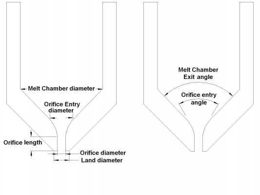
I have put together a drawing to show my present thoughts on terminology.
My present view of my own results to date and my best judgement of what I am being told is
Now all I have to do is get my technique right for drilling the orifice from inside the nozzle. Having broken all 4 of my 0.35mm drill bits I am having to try to sharpen the best of them.
Mike
Looking again at the text of the patent, I think I have to agree with Robin2 that "Land" is the flat area at the exit of the orifice.
I have put together a drawing to show my present thoughts on terminology.

My present view of my own results to date and my best judgement of what I am being told is
- The Orifice Entry diameter should be at least 3 times the Orifice diameter.
- The angle of the entry to the Orifice should be small and ideally smoothly curved.
- The angle of the Melt Chamber Exit does not significantly effect back pressure, but if too blunt will retain material between filament changes.
- The length of the Orifice should be between one and three times the Orifice diameter.
- The diameter of the Land should be less than or equal to two times the Orifice diameter.
Now all I have to do is get my technique right for drilling the orifice from inside the nozzle. Having broken all 4 of my 0.35mm drill bits I am having to try to sharpen the best of them.
Mike
|
Re: Nozzle internal geometry November 01, 2013 06:15AM |
Registered: 10 years ago Posts: 1,381 |
@ Robin2
Read the patent snippet that I posted, and look at the patent drawing, they use the term "land".
I'm accustomed to using the term land for a feature that is located between two different geometries.
Orifice length sounds like the same thing.
@ thejollygrimreaper has pointed out a very important nozzle feature, that of being flat, and no burrs.
The face of the orifice must be flat and perpendicular to the orifice axis, and free of internal burrs.
If the surface is rounded, or at an angle the extrudate will exit either randomly, spiral, or skew to one side.
This will cause the surface of the object to undulate, which will throw off dimensions and tolerances, and produce a poor finish.
|
Re: Nozzle internal geometry November 01, 2013 06:18AM |
Registered: 10 years ago Posts: 1,381 |
|
Re: Nozzle internal geometry November 01, 2013 06:49AM |
Registered: 10 years ago Posts: 1,381 |
@ leadinglights
"Now all I have to do is get my technique right for drilling the orifice from inside the nozzle. Having broken all 4 of my 0.35mm drill bits I am having to try to sharpen the best of them. "
Make a doorbell EDM machine to burn small holes into the nozzle.
You could even burn the ID profile! Use a dielectric fluid, and a plastic guide for the electrode.
Use a sewing needle as the electrode.
[www.youtube.com]
Jeri Ellsworth is also on KickStarter selling AR goggles!
[www.kickstarter.com]
|
Re: Nozzle internal geometry November 01, 2013 08:18AM |
Registered: 12 years ago Posts: 1,450 |
@A2
A project that I put on hold when I started building 3D printers is an EDM machine. For the moment though, I will keep to my old lathe.
I think I have come up with a way to do the holes:
1) Drill the inner holes, allowing the deep holes to go where they will. Include the inner profile but not the orifice.
2) Make up a plug in the lathe which accurately fits the inside of the workpiece at both ends (waisted between the ends)
3) Fit the workpiece over the plug and clamp in place somehow
4) Use a center drill to drill the end, but not through. If all has gone well this should be in line with the inner holes
5) Support the center drilled hole in a live center and turn the outside of the nozzle
6) Put in CNC mill and drill orifice hole from the outside - crossing fingers that nothing has gone wrong.
It will be a few days before I can get back to this though as I have run out of 303 stainless steel - and in any case will need larger diameter now to allow for external turning.
Mike
Edit: I just rereread the patent in conjunction with the drawing and I got a bit of a headache
The sentance
I do take your point though, there is no straight parallell portion to the orifice in that patent and that is an option that I hadn't considered.
Edited 1 time(s). Last edit at 11/01/2013 08:41AM by leadinglights.
A project that I put on hold when I started building 3D printers is an EDM machine. For the moment though, I will keep to my old lathe.
I think I have come up with a way to do the holes:
1) Drill the inner holes, allowing the deep holes to go where they will. Include the inner profile but not the orifice.
2) Make up a plug in the lathe which accurately fits the inside of the workpiece at both ends (waisted between the ends)
3) Fit the workpiece over the plug and clamp in place somehow
4) Use a center drill to drill the end, but not through. If all has gone well this should be in line with the inner holes
5) Support the center drilled hole in a live center and turn the outside of the nozzle
6) Put in CNC mill and drill orifice hole from the outside - crossing fingers that nothing has gone wrong.
It will be a few days before I can get back to this though as I have run out of 303 stainless steel - and in any case will need larger diameter now to allow for external turning.
Mike
Edit: I just rereread the patent in conjunction with the drawing and I got a bit of a headache
The sentance
followed byQuote
said orifice having a land of from to 20 mils,
I stopped reading before I got to the claims as I didnt want my brains to meltQuote
diameter. Preferabl Y is between and 28%.
I do take your point though, there is no straight parallell portion to the orifice in that patent and that is an option that I hadn't considered.
Edited 1 time(s). Last edit at 11/01/2013 08:41AM by leadinglights.
|
Re: Nozzle internal geometry November 01, 2013 08:43AM |
Registered: 11 years ago Posts: 374 |
|
Re: Nozzle internal geometry November 01, 2013 03:53PM |
Registered: 10 years ago Posts: 95 |
Having looked at the patent and its drawings I think it's important to note that it involves two nozzles - one for the optical fibres and one for the optical fibres covered with plastic. The fibre nozzle can be screwed in and out to vary its distance from the extrusion nozzle. I think the word "land" is used to refer to this distance and it may be ued in the sense that that is the space in which the goo "lands" on the optical fibres.
Also, I presume the moving optical fibre draws the "goo" through the nozzle - which might explain why a longer "land" is a bad thing.
None of this seems relevant to RepRap.
However the outer extrusion nozzle shows no depth at all. I wonder is there is lesson in that for RepRap nozzles. On the other hand, I doubt if the coated optical fibre is as thin as what RepRap people try to achieve.
...R
|
Re: Nozzle internal geometry November 01, 2013 05:43PM |
Registered: 12 years ago Posts: 1,450 |
|
Re: Nozzle internal geometry November 01, 2013 09:21PM |
Registered: 10 years ago Posts: 1,381 |
Land length:
(3) The surface of an extrusion die parallel to the direction of melt flow.
[www.brenntagspecialties.com]
Land. A term used to describe the area in which the gate, or vent, resides. It can also be thought of as the ``length'' dimension in the ``l, w, h'' terminology used for describing the dimensions of the gate or vent.
[www.plastictroubleshooter.com]
Land (Gate Area): Gate dimension parallel to the direction of melt flow.
[www.apisolution.com]
|
Re: Nozzle internal geometry November 02, 2013 06:14AM |
Registered: 10 years ago Posts: 95 |
Thanks for that @A2. You have been busy.
While it was only by accident, I think my inference from the patent application is consistent with your definitions.
Maybe this is one of those cases where I heard the word used in the past and assumed it meant something different from what the author intended - but I can't remember any examples now.
...R
|
Re: Nozzle internal geometry November 04, 2013 04:43AM |
Registered: 12 years ago Posts: 1,450 |
|
Re: Nozzle internal geometry November 04, 2013 06:20AM |
Admin Registered: 17 years ago Posts: 7,879 |
"Land" might have a specific meaning for extruders but I think in mechanics it means any flat area on an object designed to accommodate something meeting it.
[www.hydraraptor.blogspot.com]
[www.hydraraptor.blogspot.com]
|
Re: Nozzle internal geometry November 04, 2013 07:22AM |
Registered: 12 years ago Posts: 1,450 |
Hmm, so we are still in the area of terminology: While I may define the extruder as "The bit with the gears or whatnot that pushes the filament along", another may use the term for that and the hot end, or just the hot end - from which that which is extruded comes.
So still, what to call the feature that I previously knew as Land?
Face may work, but I particularly like the word Podex.
So still, what to call the feature that I previously knew as Land?
Face may work, but I particularly like the word Podex.

|
Re: Nozzle internal geometry November 04, 2013 08:22AM |
Registered: 10 years ago Posts: 1,381 |
Hot end = Die.
Die face = planar end surface = end wall = The surface adjacent the orifice.
Die angle = An internal taper which is located ahead of the land (e.g. the 118 degree drill angle).
Barrel = The region before the die angle.
If the external profile of the die (hot end) is tapered, then the geometry of "die face" is called a frustum.
Orifice entry dia = Throat (i.e. the radius feature connecting the land to the "die angle", this is the start of the compression zone).
The material exiting the orifice is called the "extrudate".
Melt swell = Swelling of the extrudate occurs at the die face (i.e. die exit), (i.e. relaxation of the internal stresses generated in the throat, and land regions).
Draw down = When you pull on the extrudate, and it's diameter is reduced (e.g. the rate of travel stretches the extrudate).
|
Re: Nozzle internal geometry November 04, 2013 09:00AM |
Registered: 12 years ago Posts: 1,450 |
Somewhere in the depths of time I had come across the word Die for something like the hot end. Most of the other words you used also echo from the depths of time whe I used to read tomes like "Machinery's Handbook" or "Metals Handbook Volume 5 Part B Melting and Casting". I further agree that we should be able to talk in the same language with people from similar fields. Perhaps there ought (maybe is??) a section on correct terminology in the Wiki.
Having said that, there is something refreshing about using words most likely to be understood by the initiate - even if this is quite often ambiguous.
Mike
Having said that, there is something refreshing about using words most likely to be understood by the initiate - even if this is quite often ambiguous.
Mike
|
Re: Nozzle internal geometry November 04, 2013 09:05AM |
Registered: 10 years ago Posts: 1,381 |
@ nophead
Agree, an example based on your definition: on a screw, the flat of the flight is called the "flight lands",
and it has a close relationship with the I.D. of the barrel.
Land (Gate Area): Gate dimension parallel to the direction of melt flow.
Land. A term used to describe the area in which the gate, or vent, resides.
Land Area: The area of surfaces of a mold which contact each other when the mold is closed.
Shutoff land. A raised area of the mold surface surrounding the cavity image.
This area is usually between 0.002 and 0.003 inch high, approximately 1/2 inch wide and is used to focus clamping pressure on the mold.
The use of a shutoff land reduces the amount of tonnage required to keep a mold closed against injection pressure.
Edited 1 time(s). Last edit at 11/04/2013 09:06AM by A2.
|
Re: Nozzle internal geometry November 04, 2013 09:25AM |
Registered: 10 years ago Posts: 1,381 |
@ leadinglights
"Having said that, there is something refreshing about using words most likely to be understood by the initiate - even if this is quite often ambiguous."
In some fields, or at a low level, I guess that would be OK.
But in the case of statistics, it's very upsetting, even maddening.
In my studies I found a PhD professor complaining about this in a paper.
He provided an example of one word with numerous renditions.
This word had about 20 different other words that meant the same thing taken from various disciplines.
Not being consistent with terms makes it massively difficult to research a topic when the words are not consistent, discoveries are lost, man kind is held back.
People naming functions after them selves, or based on the topic in which the innovation was discovered is typically how some things are named.
Statisticians really need to create a standard or cross reference between disciplines.
Edited 1 time(s). Last edit at 11/04/2013 09:35AM by A2.
|
Re: Nozzle internal geometry November 04, 2013 10:31AM |
Registered: 12 years ago Posts: 1,450 |
@A2
Far be it from me to keep back mankind. I sympathise with the PhD professor as I am perplexed by Information theorists and thermodynamasists both using the word Entropy for different things; annoyed by surveillance operatives stealing and miss-using the word Metadata and maddened by the perversion of the old computer-geek word Hacker by journalists. So I humbly suggest the following terminology for the bits of a hot end:
Die and Die face are good and have analogies with other dice such as used to put a thread on a rod or make a coin by applying force.
Barrel is un-necessary as it is not separate from the melt chamber in (as far as I know) in any existing hot end.
Land is both ambiguous and unintuitive for the earlier mentioned initiate.
Throat is excellent.
Extrudate serves to distinguish the output filament from the input filament.
Mike
Edited 1 time(s). Last edit at 11/04/2013 10:38AM by leadinglights.
|
Re: Nozzle internal geometry November 04, 2013 02:19PM |
Registered: 10 years ago Posts: 95 |
|
Re: Nozzle internal geometry November 05, 2013 03:50AM |
Registered: 12 years ago Posts: 1,450 |
|
Re: Nozzle internal geometry November 05, 2013 04:32AM |
Registered: 10 years ago Posts: 95 |
Sorry, only registered users may post in this forum.