My DIY 3D Printer approach
Posted by anthonyejones
|
My DIY 3D Printer approach January 25, 2014 08:38AM |
Registered: 10 years ago Posts: 18 |
I started getting totally interested in 3D printers just before Christmas, at the Model Engineer exhibition. Over Christmas, I decided to get a Reprap Pro Mono in the new year. When the wife asked what I needed it for, I could not answer. I realised that I really just want to build one .This takes me back to the 1980’s when I built a 3 colour plotter for my BBC computer , using scrap , meccano , an old typewriter roller and 2 steppers.
So I read and thought about it for a few weeks and have now started to build one as described below. I am sure that if it works, many uses will be found and will probably require a greater print size than Reprap.
I also envisaged using the machine as a plotter , X-Y drilling machine, light 3d router and even laser cutter??? in the future. I am not claiming that any of it is original. If it is, perhaps I am doing something wrong.
I have a milling machine , lathe and too many tools so am putting these to use where applicable. I did not see the need for the machine to be able to build itself.
The base is an offcut of 20mm MDF, 600mm X 480mm which will be sealed and painted. The Y slides are 16mm supported rail ( SBR16 with 4 linear bearing blocks ) , 600mm long. I have just received these from Hong Kong ( 11 days) ( UK prices would be too prohibitive). Attached to a 200 x 230 mm square plate, this gives a Y travel of about 410mm. The Nema 17 fits under the plate to allow full travel. I might fit 2 pulleys to the motor and use 2 belts.
The 2 vertical columns are made from 15mm acrylic which I already had. To buy this would be about £50. Could be MDF. The Z and X slides are going to be 12mm silver steel. I am planning to use a belt for the Z motion, which goes around both sides. Option 2 would be to use 2 steppers either assisting or working indepentantly. The top cross piece and X will probably also be 15mm acrylic based.
The final plate on the Z axis will be 400 X 350 mm aluminium, heated with surface mount power resistors.
The X and Z travels will be about 350 mm.
The total cost is expected to be about £300 with 1 print head.
I have attached some photos and will add more as the project progesses.
I hope that this is of interest and in the correct section and welcome any questions or comments, especially if I am going in the wrong direction.
|
Re: My DIY 3D Printer approach January 25, 2014 09:09AM |
Registered: 12 years ago Posts: 1,236 |
Looks good so far 
Given the likely mass and future uses, I would definitely consider using Nema 23 sized motors, or at least double motors on Y and Z.
What is Open Source?
What is Open Source Hardware?
Open Source in a nutshell: the Four Freedoms
CC BY-NC is not an Open Source license
Given the likely mass and future uses, I would definitely consider using Nema 23 sized motors, or at least double motors on Y and Z.
What is Open Source?
What is Open Source Hardware?
Open Source in a nutshell: the Four Freedoms
CC BY-NC is not an Open Source license
|
Re: My DIY 3D Printer approach January 25, 2014 09:22AM |
Registered: 10 years ago Posts: 18 |
|
Re: My DIY 3D Printer approach January 25, 2014 09:46AM |
Registered: 13 years ago Posts: 1,780 |
|
Re: My DIY 3D Printer approach January 25, 2014 11:07AM |
Registered: 10 years ago Posts: 18 |
Thank you. I am beginning to realise that bed weight is going to be a problem. I don't envisage using all the available volume for 3D printing. It would in any case take forever to print. I am seeing a need for long thin parts ( model aeroplane, boat parts). Perhaps I should start with a standard Reprap size bed and make specials for long shapes as required.
For the Y plane I am now considering a Nema 17 at each end operating pull pull.
For the Y plane I am now considering a Nema 17 at each end operating pull pull.
|
Re: My DIY 3D Printer approach January 26, 2014 05:43AM |
Registered: 10 years ago Posts: 95 |
I'm hoping to use my small lathe as a the "mechanics" of a small 3D printer so that the same machine can be used for CNC work and 3D printing. I got some Nema17 steppers which seem to be sufficient (it won't have fast motion) and in the last couple of months I have been sidetracked by a model railway project.
In my concept the extruder will be stationary and the work-base will move in three dimensions below it.
...R
In my concept the extruder will be stationary and the work-base will move in three dimensions below it.
...R
|
Re: My DIY 3D Printer approach January 26, 2014 12:44PM |
Registered: 10 years ago Posts: 18 |
Thank you. I have been thinking about speed. If I have to slow down the Y motion due to mass, presumably the other 2 planes need to be slowed down by equal amounts to match. I have not looked but is there a parameter to set this?
Edited 1 time(s). Last edit at 01/27/2014 04:12PM by anthonyejones.
Edited 1 time(s). Last edit at 01/27/2014 04:12PM by anthonyejones.
|
Re: My DIY 3D Printer approach January 26, 2014 02:10PM |
Registered: 13 years ago Posts: 1,780 |
For 3D printing with FDM, the z axis can be a lot slower than the other 2 axes. Usually, it's only changed when the printer steps into the next z layer although the autoleveling method in use nowadays does change z during x-y moves to compensate for the angle of the bed. There are separate settings for maximum speed, acceleration and jerk for each axis in the firmware, including the extruder.
|
Re: My DIY 3D Printer approach January 27, 2014 04:37AM |
Registered: 10 years ago Posts: 18 |
|
Re: My DIY 3D Printer approach January 28, 2014 07:33AM |
Registered: 10 years ago Posts: 18 |
Just received the Z and X 12mm rod supports and linear bearings ( China again ). Shown in photo laid out on what will be the vertical column. Also shows fabricated aluminium bracket for columns. If you have ever seen the Swedish aluminium welding man at exhibitions, yes it does work.
Edited 1 time(s). Last edit at 01/28/2014 07:34AM by anthonyejones.
Edited 1 time(s). Last edit at 01/28/2014 07:34AM by anthonyejones.
|
Re: My DIY 3D Printer approach January 29, 2014 07:18AM |
Registered: 10 years ago Posts: 95 |
|
Re: My DIY 3D Printer approach January 29, 2014 02:01PM |
Registered: 10 years ago Posts: 18 |
Hello, Yes , about 5 feet. I have been watching him for years at Model Engineer exhibitions in London area. I finally purchased some last December ( £30 ). I really does work. I have repaired castings and now welding the corners of ali angle. It seems expensive but to repair a casting with a 1 1/2" weld used less than 1/2" of wire. ( 30p)
|
Re: My DIY 3D Printer approach January 30, 2014 07:00AM |
Registered: 10 years ago Posts: 18 |
The attached photos show a Z axis. The rod is 12mm silver steel ( £12.50 per metre). This has a ground finish, not as good as the SBR16 Y slides so will polish with Brasso and cardboard. The block is machined out of 20mm acrylic and shows the X motor and X slide blocks. This arrangement sets the X slides vertically above each other. This gives maximum travel for X. Not sure of the pros and cons of having the X slides in the horizontal or vertical plane.
With the block shown, the Z travel is about 30 cm. The effective range will be reduced by the thickness of a heated bed. I planned to use a belt for the Z travel but have just realised that the leadscrew gives a fine resolution of 0.8mm travel per motor rev ( assuming that is the pitch ). To use a belt I will need a reduction of about 40:1. Good old Meccano gears come immediately to mind and in the absence of anything else may be used initially (with proper shafts and bearings). The worm gear will also act as a brake and hopefully the weight of the X mechanism will keep the gears meshed in one direction and overcome the backlash. Still not keen on the leadscrew method.
With the block shown, the Z travel is about 30 cm. The effective range will be reduced by the thickness of a heated bed. I planned to use a belt for the Z travel but have just realised that the leadscrew gives a fine resolution of 0.8mm travel per motor rev ( assuming that is the pitch ). To use a belt I will need a reduction of about 40:1. Good old Meccano gears come immediately to mind and in the absence of anything else may be used initially (with proper shafts and bearings). The worm gear will also act as a brake and hopefully the weight of the X mechanism will keep the gears meshed in one direction and overcome the backlash. Still not keen on the leadscrew method.
|
Re: My DIY 3D Printer approach February 03, 2014 12:34PM |
Registered: 10 years ago Posts: 18 |
This photo shows a scrap aluminium block which had a stepper motor bracket / gearbox housing hiding inside for the last 20 years. This uses 2 meccano gears drilled out to 5mm bore with silver steel shaft and ball bearings. This gives a 38:1 ratio for the Z axis belt drive. There seems very little backlash and hopefully the constant downward force will overcome this. Also the other one will be working in reverse direction which might help. I have tested it running. It is amazingly powerful at the belt pulley output.
Got to make a second housing now. Wish I had a 3d printer for these !. Seems an ideal candidate. Which leads me to a question :
What are the stages / software are required to get from my sketch of the housing through to a printed part ??
Edited 1 time(s). Last edit at 02/04/2014 04:25PM by anthonyejones.
|
Re: My DIY 3D Printer approach February 28, 2014 02:38PM |
Registered: 10 years ago Posts: 18 |
These photos show the completed mechanics. As it might sit on the dining room table for extended periods, I have added some matching edging. The bed plate has been changed to save weight for the benefit of 3D and now uses only 3 linear bearings. It is 27cm X 25 cm
The end stops will be slotted Opto switches. These allow the actuator blade to pass through and for Y and X there may 2 selectable switches to cater for alternative bed sizes and travel. I was surprised to see that end stops are only fitted to one end of REPRAP etc. but RAMPS and the software caters for end stops at both ends.
I am now concentrating on the electronics. This will be Arduino / RAMPS . For the Y and Z dual motors, I will use a driver for each motor on a separate board which connects to a RAMPS single socket. I think it will be useful in the future to be able to control the Z motors independently for leveling. I am using Marlin firmware as this seems to be the most talked about and looks modifiable. It also compiles OK although having said that, I have 2 Marlin downloads V1 and another which both compile but the other one has Marlin_main.cpp missing. I also fly drones, using Arduino based autopilots, the configuration control for this software is also a problem. For the host I have currently got ReplicatorG , again because it seems to run OK.
The aim now is to get the machine running through the motions of printing something but I am also thinking about the hot end and extruder. I like the look of the E3D hot end . The people there are also helpful.They say that direct systems give better results than bowden but I am concerned with the weight of up to 3 of these with extruders on the X head in the future. Also deciding on whether to use 1.75 or 3mm filament . I am not sure of the pros and cons of each.
It would be nice to fit a pen and have the machine write ‘HELLO’ . Can anyone suggest some software to enable this and in the future, 2D cutting.
|
Re: My DIY 3D Printer approach March 01, 2014 12:16AM |
Registered: 10 years ago Posts: 1,381 |
Nice looking printer.
If I'm interpreting your design correctly is should be working like this:
The stepper pulley on the left should be rotating clockwise, and the stepper pulley on the right should be rotating counter clockwise.
The lower stepper driven pulley should be applying a downward tension to the belt that is furthest from the bearing shaft (i.e. between the Z axis).
The top pulley located on the gantry will be pulling up on the belt nearest the bearing.
So the steppers should be running in opposite directions as you have them laid out.
With this layout here is no reducing the backlash, other than adding more weight to the X axis carriage.
If you plan to use it as a light 3d router, threaded Z axis rods should be used, but I guess it depends on your definition of light, (i.e. foam).
Use GT2 belts, with an appropriately sized pulley.
15 mm acrylic can also be solvent welded, large fish tanks are constructed this way.
This would spread the stress, and vibrations out over a larger area than what a bolt can do, reduce the weight, and component count.
You should also add a large washer under the head of the bolt, and radius/chamfer the holes to reduce stress crazing around the holes.
I like the worm drive Z axis.
Quote
anthonyejones
There seems very little backlash and hopefully the constant downward force will overcome this.
Also the other one will be working in reverse direction which might help.
If I'm interpreting your design correctly is should be working like this:
The stepper pulley on the left should be rotating clockwise, and the stepper pulley on the right should be rotating counter clockwise.
The lower stepper driven pulley should be applying a downward tension to the belt that is furthest from the bearing shaft (i.e. between the Z axis).
The top pulley located on the gantry will be pulling up on the belt nearest the bearing.
So the steppers should be running in opposite directions as you have them laid out.
With this layout here is no reducing the backlash, other than adding more weight to the X axis carriage.
If you plan to use it as a light 3d router, threaded Z axis rods should be used, but I guess it depends on your definition of light, (i.e. foam).
Use GT2 belts, with an appropriately sized pulley.
15 mm acrylic can also be solvent welded, large fish tanks are constructed this way.
This would spread the stress, and vibrations out over a larger area than what a bolt can do, reduce the weight, and component count.
You should also add a large washer under the head of the bolt, and radius/chamfer the holes to reduce stress crazing around the holes.
I like the worm drive Z axis.
|
Re: My DIY 3D Printer approach March 27, 2014 11:35AM |
Registered: 10 years ago Posts: 18 |
Thank you A2 for your comments.
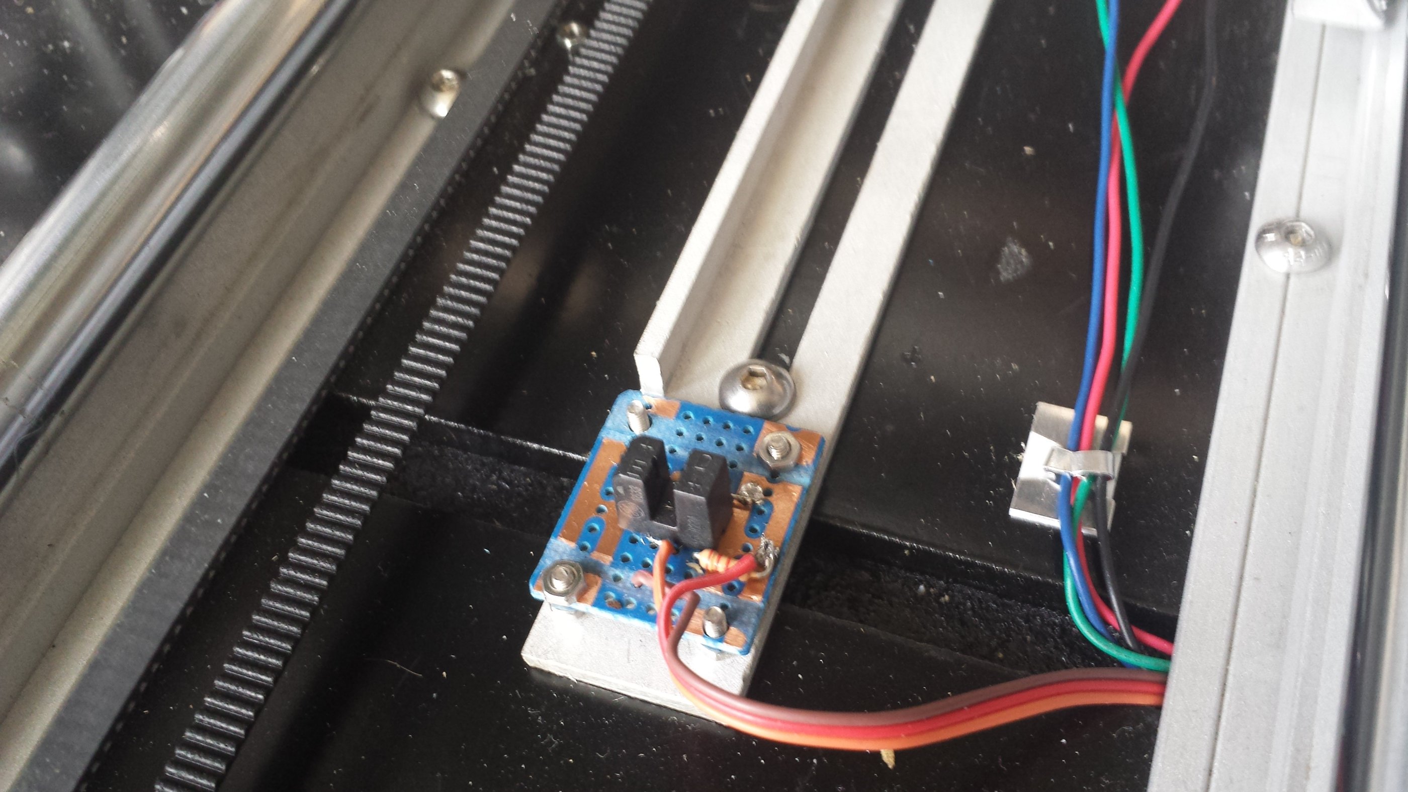
The next 3 photos show the end stops. These are opto slotted type on the 3 MIN ends. The X and Y are moveable to allow for other bed sizes. The Z has a small range to cater for TBD tooling and has a fine adjustment also. The Z motors have a driver each. These being piggybacked with the motor pins bent out.This saved the serial /parallel decision and also allows one to be disabled to allow for levelling.
All 3 axes now moving OK. The Z gearboxes are performing well. These give 950 steps per mm but using only x4 microstepping. I have done a dummy run using snake.stl. I commented out the temperature commands in the Gcode and forced the temp to 235 using a suitable resistor in place of the thermistor in the absence of a hotend. Not sure if this was necessary. I fitted a pen to the X head and disabled Z. The next photos show the result which I am very pleased with. The 4 plots are layers .35 to 2.75mm , to 4.75 mm , to 6.75 mm and to finish.
I have set the calibration to the theoretical values but have not verified them yet. The snake perimeter on the plot is 122mm long.
Now eager to get a hotend and extruder. Have been looking at the E3D hotend and kVr direct drive extruder. Not sure whether to get 1.75 or 3mm, direct or bowden but do intend fitting 1 or 2 more.
I am using Pronterface / slic3r and Marlin. Thank you to those who made these available. I have tried ReplicatorG but it seems to get stuck on estimating the print time.
|
Re: My DIY 3D Printer approach May 10, 2014 05:34PM |
Registered: 10 years ago Posts: 18 |
It works!!!
The next 3 photos show the extruder. Again milled from a block of acrylic. It uses a MK7 pulley and 2.4 : 1 gearing ( Meccano again ). Works very well. The extruder is fitted with an E3D 1.75 hotend with a 0.4 nozzle.
The next photo shows the completed machine. I am currently using a standard heated bed ( MK2a) @ 12 volts with a 20cm x 20cm glass kitchen worktop protector. I will look at other bed sizes as and when required. I suspect that this will be a longer , narrower one.
Eager to test the machine , I ran the snake gcode that I had been using previously for preliminary testing.. Using PLA, the result is in the next photo , on the left. Whilst amazed that it actually produced something, the final result did not look right. I then realised that the gcode was set for 3mm filament and a 0.5 nozzle so I suppose that it produced a ‘draft’ version , using only half the material.
After correcting the parameters , the next snake in the photo was produced which looked much better. I then made a 40 tooth ‘Lego’ gear which looked ok. The next object was supposed to be a ball in a box but was aborted after a few mm. The ball moved about and the outer looked a complete mess.
Disheartened by this, I thought that I would print some test / calibration objects ( see next photo ). These came out much better that expected. The 0.5mm thin wall was 0.59mm. The 20mm box was 20mm with the top successfully bridged. The 50mm tower also worked ok, without any cooling fan. For all of the these, I used ABS at 225 deg with a bed at 110. Based on these, the settings look fairly ok, so I am not sure what is wrong with the ball in box but there does seem very little to hold the ball in place on the bed. I have however, subsequently produced a good ball in box after reducing the filament flow slightly and changing the infill method.
I have become familiar with Openscad basics after a few days playing. Having no initial knowledge , I found the examples off putting but setting out to create something that I actually needed and learning what is required to achieve it, seems a good approach. It helped me to think in terms of milling machine operations, starting with a block or cylinder and removing sections and drilling holes. I am now producing my own Openscad parts for my other expensive arduino controlled toy … auto piloted flying drones ( see last photo ). As an exercise, I have also produced an Openscad model for the Z gearboxes. This introduced the ‘for loop’ to produce the slotted motor mounting holes ( milling analogy again ). Using just cylinder , cube , sphere , difference , translate and rotate, most mechanical parts can be produced.
The machine has run for a total of about 48 hours now. Very pleased with the E3d nozzle and the machine in general. Infilling of small areas sometimes causes some violent movements so need to look at acceleration. The bed heating time needs to be improved and one of the Z motors does not like fast movements so may require replacing although I may change the firmware to only allow slow Z movements. I currently edit each Gcode as the first Z movement seems to be too fast. I have found the fine control on the Z end stop is very useful. Leveling is achieved by turning one of the worm gears. I don't see the need for auto leveling.
When I started this project back in January, I envisaged a multi use machine. Now having used it, and with a queue of jobs for it, the machine will remain a 3D printer although I might investigate a laser cutting head sometime.
Thank you to everyone who have read these message postings . Also thank you to all who made the concepts, software ( Marlin , pronterface , slic3r and openscad ) and .stl examples available.
Edited 3 time(s). Last edit at 05/12/2014 09:58AM by anthonyejones.
|
Re: My DIY 3D Printer approach May 11, 2014 06:04PM |
Registered: 13 years ago Posts: 248 |
Hi Anthony,
Congratulations! Well done and thanks for sharing your work. Always interesting to see how others get on with building from scratch. You can learn so much by doing it this way, and have many hours of enjoyment. It's not the way for everyone but looks like you are doing well and getting great satisfaction from the project.
Regards,
NumberSix
|
Re: My DIY 3D Printer approach May 12, 2014 02:27AM |
Registered: 11 years ago Posts: 1,592 |
|
Re: My DIY 3D Printer approach May 12, 2014 04:28AM |
Registered: 10 years ago Posts: 86 |

|
Re: My DIY 3D Printer approach May 12, 2014 04:39AM |
Registered: 10 years ago Posts: 32 |
|
Re: My DIY 3D Printer approach May 12, 2014 05:37AM |
Registered: 10 years ago Posts: 18 |
Hello All, Thank you for all your replies. My milling machine is an old Elliott U0. Probably large by home standards. Literally weighs 1 ton and has a 36" bed. A smaller mill will be ok, except for the long uprights but you could use a hand held router for these instead. The cutters were ordinary slot drills and end mills, not running particularly fast
After 1 1/2 weeks use , I am already wondering how I managed without one and already producing and using the parts. For my next extruder and any other parts, I already think of using Openscad and the printer.
I have thoroughly enjoyed the experience of the project. As a retired software engineer and hobby machinist , it is good to combine the two. I know that I have 're invented the wheel' l in several places but it is good the share the thought processes with the originators.
The resultant printer is quite heavy, but I think that weight and rigidity is important. Even the milling machine sometimes complains about producing a part, 1/4000 of it's weight!! The extra long Y travel of the printer will be useful in the future. There is also some extra X and Z travel but I cannot imagine using all three extremes at once!
Edited 2 time(s). Last edit at 05/12/2014 11:07AM by anthonyejones.
|
Re: My DIY 3D Printer approach March 07, 2015 04:44AM |
Registered: 9 years ago Posts: 11 |
|
Re: My DIY 3D Printer approach June 06, 2015 07:43AM |
Registered: 10 years ago Posts: 18 |
.
Thank you for your posting and good luck with your project.
One year on, I thought that I would post an update. The printer has now just passed 400 hours of use, with the E3d V5 hotend and 1 new nozzle.
In collaboration with 3dFilaprint / GlobalFsd I have just produced 2 openscad designs attached. A MkII version of the marble machine and a third major design will follow shortly. All require the new bed size , having parts 340 mm long.
I have added a 350 x 300 mm bed. This is only however heated all over up to PLA bed temperatures . I have slightly modified the extruder with a tube to allow the use of NInjaflex. I have added a thermocouple hotend sensor . The benefit of this is mainly avoiding fitting the thermistor.
The features that I have built in and now appreciate are:
Rigidity
large bed size
opto endstops
micro adjust z end stop
flat and level bed.
Sorry, only registered users may post in this forum.