LM8UU ball groove orientation
Posted by Dirty Steve
|
LM8UU ball groove orientation February 14, 2014 09:42AM |
Registered: 11 years ago Posts: 560 |
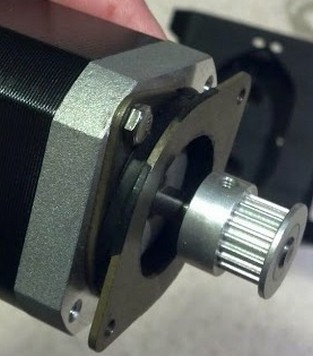
I just upgraded my steppers and I am getting a lot of chatter from my x-carriage bearings, which has always been there, but more so with the motor upgrade.
What is the best way to have the bearings rotationally oriented? I have the LM8UU riding on the rods so that the ball grooves in the bearing are at 45 degrees to vertical/horizontal. Is this the correct orientation for the bearings or should they be perpendicular to vertical/horizontal? I can't find any reference to this online. I have the bearings in press fit holders and they will be a little work to rotate.
Edited 2 time(s). Last edit at 02/14/2014 10:02AM by Dirty Steve.
|
Re: LM8UU ball groove orientation February 14, 2014 10:53AM |
Registered: 10 years ago Posts: 1,381 |
Are you using a harden precision ground steel shaft?
Small diameter bearings are sensitive to slight variation of the shaft diameter.
Orientated at 45 deg is good.
[www.heason.com]
Edited 1 time(s). Last edit at 02/14/2014 07:20PM by A2.
Small diameter bearings are sensitive to slight variation of the shaft diameter.

Orientated at 45 deg is good.
[www.heason.com]
Edited 1 time(s). Last edit at 02/14/2014 07:20PM by A2.
|
Re: LM8UU ball groove orientation February 14, 2014 01:37PM |
Registered: 10 years ago Posts: 20 |
Have you tried setting your motor currents? I had a really noisy printer when I first built it and later when I calibrated (lowered) the motor currents (not too low) the noise reduced greatly. I don't know if the vibration from the motor runs through the bearings, but now you only hear the buzzing of the motor. I have the same bearings as you as well. Just a suggestion.
|
Re: LM8UU ball groove orientation February 14, 2014 05:07PM |
Registered: 11 years ago Posts: 560 |
|
Re: LM8UU ball groove orientation February 14, 2014 07:26PM |
Registered: 10 years ago Posts: 1,381 |
|
Re: LM8UU ball groove orientation February 14, 2014 07:46PM |
Registered: 10 years ago Posts: 553 |
did you try changing out the bearings? Might be a dud bearing.
greghoge.com
HUGE 3D PRINTER PARTS SALE!!!
greghoge.com
HUGE 3D PRINTER PARTS SALE!!!
|
Re: LM8UU ball groove orientation February 14, 2014 07:55PM |
Registered: 11 years ago Posts: 560 |
|
Re: LM8UU ball groove orientation February 14, 2014 08:04PM |
Admin Registered: 13 years ago Posts: 730 |
Dirty Steve, you have a reputation for getting fantastic quality prints. I have a feeling that what is "a lot of chatter" for you would be "pretty damn good" for the rest of us.  Can you post a picture of the print surface where you see the effects?
Here is my wild guess: Your upgraded stepper motors have a higher (or perhaps lower) stiffness. By stiffness in this context I mean "the amount the output shaft would rotate in response to an applied torque while the motor is holding". I guess another term one might use is the "mechanical impedance" of the stepper motor.
This change in stiffness has brought the resonant frequency of your system closer to the frequencies that you commonly operate at, hence the amplitude of the unwanted vibrations is higher. You could test or possibly mitigate this by adding damping (on or around the motors?), by changing the mass of the carriage, or by operating at a different speed... Just some ideas, nothing more.
Can you post a picture of the print surface where you see the effects?Here is my wild guess: Your upgraded stepper motors have a higher (or perhaps lower) stiffness. By stiffness in this context I mean "the amount the output shaft would rotate in response to an applied torque while the motor is holding". I guess another term one might use is the "mechanical impedance" of the stepper motor.
This change in stiffness has brought the resonant frequency of your system closer to the frequencies that you commonly operate at, hence the amplitude of the unwanted vibrations is higher. You could test or possibly mitigate this by adding damping (on or around the motors?), by changing the mass of the carriage, or by operating at a different speed... Just some ideas, nothing more.
|
Re: LM8UU ball groove orientation February 15, 2014 11:21AM |
Registered: 10 years ago Posts: 1,381 |
Quote
Dirty Steve
I am getting a lot of chatter from my x-carriage bearings
It's a chatter in my X-carriage, it shows up in my print surfaces
I've designed fixtures with miniature linear bearings, and they can be a PITA.
It's easy to generate "jittering" with little ball bearings, and it can be quite the mystery to solve.
Best you can do is keep changing things until it works.
Things to consider:
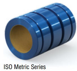
Switch to sintered bronze bushings, or the plastic coated aluminum bushings.
Adjust the bearing pre-load.
Bearing is worn out.
Rotate bearing orientation.
Bearing is rotating (loose).
Bearing quality-grade is too low.
Over-press: shaft is too big for the bore or the housing is too small for the OD of the bearing.
Remove the grease, could be contaminated, and can cause balls to slide and not roll.
Use oil instead of grease.
Don't use mineral oil, i.e. WD40 as it attracts dirt.
Failing belt.
Belt tension too high.
Belt not parallel to shaft.
Shaft is bend or flexing.
Shaft material is not what you think it is.
Wipers have folded under bearing.
Wipers are too stiff, remove the wipers, use felt.
Not enough mass, or too much mass.
Pulley is off center.
Pulley axis is flexing.
Pulley out of round.
Pulley is vibrating due to frame, or panel harmonics.
Toothed pulley vs. smooth pulley surface.
Bearings over constrained: Floating bearing set is performing like a fixed bearing set, (four-bearing, two-rail system).
Parallel shafts are misaligned causing binding, (floating bearings compensates for angular rail misalignment).
Binding Ratio: Drive force is not offset more than ~twice the bearing separation length, (binding or chattering of the system can occur).
@MattMoses:
Paraphrasing your comment:
The stepper motor should have some slip, to smooth out discrete movement.
By adding a dampening component you can also smooth out the discrete movement.
Motor settling time (harmonics): Video
[www.linengineering.com]

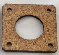
Cork dampener, (natural, rubberized):
[www.sciencedaily.com]
[www.ebay.ch]
[www.makerbot.com]
[www.thingiverse.com]

Harmonic dampener:
[www.youtube.com]
[www.linengineering.com]

Astrosyn dampers:
[astrosyn.com]
[www.youtube.com]
[www.youtube.com]
[3d.grabercars.com]
Rippling, Vibration and Resonance
[wiki.arcol.hu]
Consider also:
Nylon bolts to isolate harmonics.
Through holes use a rubber bushing to isolate the frame, or panel from the bolt, POP® Well-Nut® Threaded Inserts.
Fly wheel, extra mass added to a double shaft stepper.
Preload, moment, bearing life:
[www.ozak.com.sg]
[www.ozak.com.sg]
Demystifying the 2:1 Ratio and the Stick-Slip Phenomenon
[www.pbclinear.com]
Edited 2 time(s). Last edit at 02/15/2014 01:21PM by A2.
|
Re: LM8UU ball groove orientation February 15, 2014 11:31AM |
Registered: 11 years ago Posts: 560 |
|
Re: LM8UU ball groove orientation February 15, 2014 11:38AM |
Admin Registered: 11 years ago Posts: 3,096 |
Quote
A2
Are you using a harden precision ground steel shaft?
Small diameter bearings are sensitive to slight variation of the shaft diameter.
Orientated at 45 deg is good.
[www.heason.com]
Great to see this, I already felt like this was the way it 'should' be done but I could never find anything about it so just figured this should be the way to go
Using hardchromed rods btw. Those babies roll like never before!And what A2 says:
Quote
Switch to sintered bronze bushings, or the plastic coated aluminum bushings
I switched back from those PTFE-lined bushings to LM8UU because they were hard to install correctly. Especially my X-carriage would have either wobble or banding since those bushings are push-fit and these bushings are very sensitive to alignment. I would then recommend the Bronze self-aligning bushings because they have a play of 5º both ways which is more than enough to make up for any incorrect alignment in other parts. If I hadn't had those 12 LM8UU bearings laying around I would've gotten myself a bunch of those self-aligning bronze bushings
Edited 1 time(s). Last edit at 02/15/2014 11:43AM by Ohmarinus.
|
Re: LM8UU ball groove orientation February 15, 2014 11:52AM |
Registered: 10 years ago Posts: 1,381 |
|
Re: LM8UU ball groove orientation February 15, 2014 12:40PM |
Registered: 10 years ago Posts: 1,381 |
@Ohmarinus:
I like Simplicity Frelon bearings, expensive.
They also sell coated shafts, and the combination is silky smooth.
They have competitors, shop around.
Should be used only in a loaded orientation.
Vertical Z axis is not recommended.
.0005" per side clearance average.
Vibration damping.
[www.pbclinear.com]
[www.mcmaster.com]
Edited 1 time(s). Last edit at 02/15/2014 12:41PM by A2.
|
Re: LM8UU ball groove orientation February 15, 2014 01:03PM |
Admin Registered: 11 years ago Posts: 1,063 |
yeah these lm8uu's are fun , i'm finding myself that they develop a bit of chatter after a while, i generally replace the lm8uu's every 3 to 6 months, but this is on printers that are running 24/7, if you push them long enough they can fail spectacularly and make heaps of noise or refuse to run on one direction
I'm waiting on some PTFE rod which i'm going to put and 8mm hole through and turn down to a lm8uu sized slug and use those, if you put those on brand new smooth rod and spray the rod occasionally with a bit of dry lube or a drop or two of oil, i'm told they practically last forever,
depending on how much printing you are doing it might also be worth looking into some printed nylon lm8uu's, there's a trick to those as well, print them slightly undersized and put a 8mm drill bit through them, I've had those last a while
-=( blog )=- -=( thingiverse )=- -=( 3Dindustries )=- -=( Aluhotend - mostly metal hotend)=--=( Facebook )=-
|
Re: LM8UU ball groove orientation February 15, 2014 02:07PM |
Registered: 10 years ago Posts: 1,381 |
@thejollygrimreaper:
Make a fixture to hold the Teflon.
Teflon deform very easily in a vice or 4 jaw chuck.
You might be able to get away with a ridged PVC pipe fit to the O.D..
I've found a parabolic drill works best with plastic.
Center drill, then pilot hole drill the diameter of the drill webbing, before going to size.
When boring Teflon, the plastic tends to push away from the cutter.
To prevent cutting a linear grove after you bore or drill through, stop the cutter, remove the part from the fixture,
and then push the drill through in the direction that you started drilling.
You might have to take multiple passes, or trial different size drills to get the diameter you desire.
Don't let the tool spin idly in the bored hole, the plastic will heat up and expand creating a barrel shaped bore.
MACHINING PLASTICS
[doc.nit.ac.ir]
Edited 1 time(s). Last edit at 02/15/2014 02:07PM by A2.
Make a fixture to hold the Teflon.
Teflon deform very easily in a vice or 4 jaw chuck.
You might be able to get away with a ridged PVC pipe fit to the O.D..

I've found a parabolic drill works best with plastic.
Center drill, then pilot hole drill the diameter of the drill webbing, before going to size.
When boring Teflon, the plastic tends to push away from the cutter.
To prevent cutting a linear grove after you bore or drill through, stop the cutter, remove the part from the fixture,
and then push the drill through in the direction that you started drilling.
You might have to take multiple passes, or trial different size drills to get the diameter you desire.
Don't let the tool spin idly in the bored hole, the plastic will heat up and expand creating a barrel shaped bore.
MACHINING PLASTICS
[doc.nit.ac.ir]
Edited 1 time(s). Last edit at 02/15/2014 02:07PM by A2.
|
Re: LM8UU ball groove orientation February 15, 2014 04:48PM |
Admin Registered: 11 years ago Posts: 1,063 |
Quote
A2
@thejollygrimreaper:
Make a fixture to hold the Teflon.
Teflon deform very easily in a vice or 4 jaw chuck.
You might be able to get away with a ridged PVC pipe fit to the O.D..
I've found a parabolic drill works best with plastic.
Center drill, then pilot hole drill the diameter of the drill webbing, before going to size.
When boring Teflon, the plastic tends to push away from the cutter.
To prevent cutting a linear grove after you bore or drill through, stop the cutter, remove the part from the fixture,
and then push the drill through in the direction that you started drilling.
You might have to take multiple passes, or trial different size drills to get the diameter you desire.
Don't let the tool spin idly in the bored hole, the plastic will heat up and expand creating a barrel shaped bore.
MACHINING PLASTICS
[doc.nit.ac.ir]
i just use a collet and wrap sandpaper around the outside of the teflon rod , for putting holes in i normally just use a brand new nice and sharp drillbit and start from 3mm and work my way up from there,
-=( blog )=- -=( thingiverse )=- -=( 3Dindustries )=- -=( Aluhotend - mostly metal hotend)=--=( Facebook )=-
|
Re: LM8UU ball groove orientation February 16, 2014 05:27PM |
Admin Registered: 11 years ago Posts: 1,063 |
Quote
Dirty Steve
I just upgraded my steppers and I am getting a lot of chatter from my x-carriage bearings, which has always been there, but more so with the motor upgrade.
What is the best way to have the bearings rotationally oriented? I have the LM8UU riding on the rods so that the ball grooves in the bearing are at 45 degrees to vertical/horizontal. Is this the correct orientation for the bearings or should they be perpendicular to vertical/horizontal? I can't find any reference to this online. I have the bearings in press fit holders and they will be a little work to rotate.
how much printing are you doing anyway?
a very recent conversation i had with a friend of mine , has yielded a gcode odometer counter program which has really opened my eyes in terms of how much the lm8uu's get subjected to, a classic example on my machine:
if i print 4 plates totalling 1.6km worth of movement on the x axis (i3 rework) at a rate of 1set/day i'm looking at 48kms /month or 144km / 3months or 288km/6 months
this is actually one hell of a distance for these bearings considering the cost of them and that some of us are running them on smooth stainless rod instead of the hardened ground rod , personally i'm not going to be complaining about bearing failures in the future.......
-=( blog )=- -=( thingiverse )=- -=( 3Dindustries )=- -=( Aluhotend - mostly metal hotend)=--=( Facebook )=-
|
Re: LM8UU ball groove orientation February 16, 2014 06:27PM |
Registered: 10 years ago Posts: 1,381 |
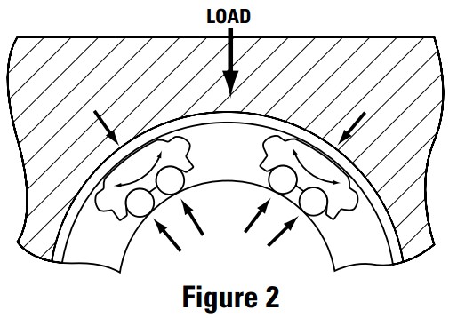
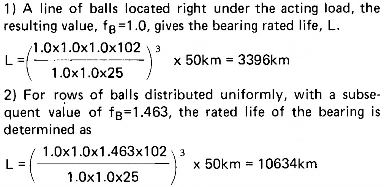
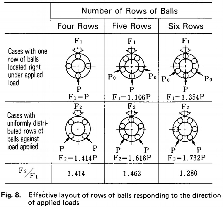
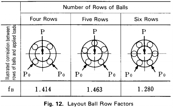
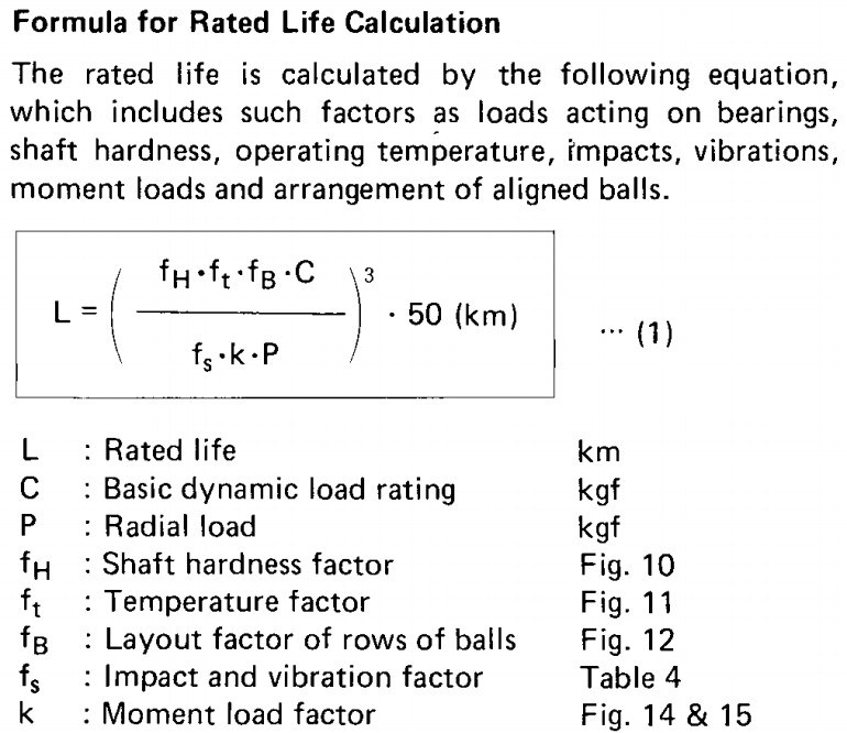
Ball orientation vs. life of the bearing
[www.ozak.com.sg]
With a single row of balls aligned under the load bearing life is less when compared to a distributed ball orientation under the load.
Edited 1 time(s). Last edit at 02/16/2014 06:28PM by A2.
[www.ozak.com.sg]
With a single row of balls aligned under the load bearing life is less when compared to a distributed ball orientation under the load.


Edited 1 time(s). Last edit at 02/16/2014 06:28PM by A2.
|
Re: LM8UU ball groove orientation February 16, 2014 07:30PM |
Admin Registered: 11 years ago Posts: 1,063 |
thats for a high-ish quality japanese bearing, not the 50cent stuff we tend to get
-=( blog )=- -=( thingiverse )=- -=( 3Dindustries )=- -=( Aluhotend - mostly metal hotend)=--=( Facebook )=-
|
Re: LM8UU ball groove orientation February 16, 2014 08:04PM |
Registered: 10 years ago Posts: 1,381 |
Quote
thejollygrimreaper
thats for a high-ish quality japanese bearing, not the 50cent stuff we tend to get
That is incorrect, the formula accounts for many things such as the hardness of the shaft, take a look at the variable inputs.

Edited 1 time(s). Last edit at 02/16/2014 08:04PM by A2.
Sorry, only registered users may post in this forum.