Wallace Questions
Posted by Matidas
|
Wallace Questions March 17, 2014 12:21AM |
Registered: 10 years ago Posts: 5 |
Sorry if this is in the wrong place, I'm just not sure where to put it  I had a few questions about the Wallace type 3D Printer. I was wondering if it would be possible to make one with a print area of 100x50x50, and if using M8 treaded rods would be better than M6 rods. Also, I'm not sure where to get the parts that need to be 3D printed, since I don't have a 3D printer yet. The last question I'd like to ask is whether or not it would be possible to use dual extruders so I could print in two types of plastics. These are probably some really easy questions, but I thought it'd be better to ask rather than assuming and messing up
  Any help would be appreciated
 I had a few questions about the Wallace type 3D Printer. I was wondering if it would be possible to make one with a print area of 100x50x50, and if using M8 treaded rods would be better than M6 rods. Also, I'm not sure where to get the parts that need to be 3D printed, since I don't have a 3D printer yet. The last question I'd like to ask is whether or not it would be possible to use dual extruders so I could print in two types of plastics. These are probably some really easy questions, but I thought it'd be better to ask rather than assuming and messing up
  Any help would be appreciated
|
Re: Wallace Questions March 17, 2014 10:13AM |
Registered: 12 years ago Posts: 258 |
Yes, you can make a 100x50x50 print area Wallace. The printed parts are all the same no matter the working area, but the threaded rods would be different. Running the v1 branch of the code through OpenSCAD would calculate the rod lengths you'd need for different build areas. You could make it with longer rods in the Y and Z directions and let them stick out until you decided to cut them off. In X, the X-ends wrap around the end of the smooth rods, so you'd need to replace the X smooth rods with differently sized rods if you wanted to change that length.
M8 would be stiffer, and maybe better for a larger machine. The M8 printed parts would be different than the M6 printed parts.
I had my parts printed by fabbr: [www.fabbr.com]
You can use dual extruders, but the pair of extruders could be wider than a single, and could eat into the X travel, which you could fix by replacing the X-axis rods.
|
Re: Wallace Questions March 17, 2014 11:18AM |
Registered: 10 years ago Posts: 5 |
|
Re: Wallace Questions March 17, 2014 01:30PM |
Registered: 12 years ago Posts: 35 |
Try here!
[forum.conceptforge.org]
*Edit*
Sorry got confused with Wallace with Wally.
Edited 1 time(s). Last edit at 03/18/2014 10:51AM by gyronictonic.
[forum.conceptforge.org]
*Edit*
Sorry got confused with Wallace with Wally.
Edited 1 time(s). Last edit at 03/18/2014 10:51AM by gyronictonic.
|
Re: Wallace Questions March 17, 2014 09:34PM |
Registered: 10 years ago Posts: 5 |
|
Re: Wallace Questions March 18, 2014 12:10AM |
Registered: 12 years ago Posts: 258 |
Quote
Matidas
I'm not well versed in Openscad, so I'm not sure how to run the code.
I downloaded the code from [github.com] ,
switched to the v1 branch with 'git checkout v1'
changed the [x,y,z] build volume in 'wallace.scad' from [200,200,95] to [100,50,50]
and opened with Openscad and compiled it.
The compilation computes these rod lengths:
ECHO: "X rod length: ", 250.5
ECHO: "Y rod length: ", 132
ECHO: "Z rod length: ", 230.1694173824159
ECHO: "foot rod length: ", 99
ECHO: "leadscrew length: ", 130.1694173824159
ECHO: "base rod length: ", 234.5
ECHO: "top rod length: ", 218.5
Almost nothing depends on the Y rod length, so you could leave it long and cut it later. Or replace it after the fact with a longer rod. Z is similar, though any changes to the length of the Z-rods should be applied to the leadscrews as well.
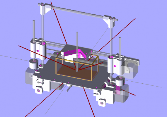
Attached is an OpenSCAD rendering of an [100,50,50] build volume.
With the smaller-than [200x200x95] volume, I think you'd be fine with the 6mm and M6 rods.
|
Re: Wallace Questions March 18, 2014 09:20PM |
Registered: 10 years ago Posts: 5 |
|
Re: Wallace Questions March 19, 2014 02:11AM |
Registered: 12 years ago Posts: 258 |
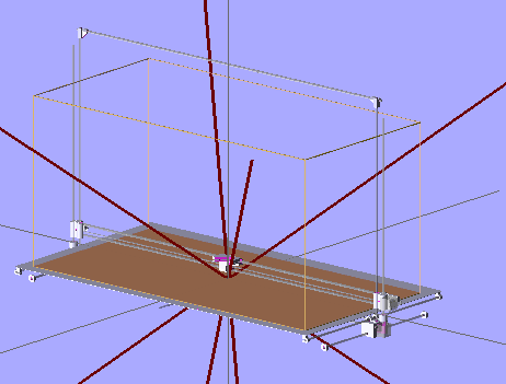
Re-running it with [1000,500,500] would get you these values:
Compiling design (CSG Tree generation)...
ECHO: "X rod length: ", 1150.5
ECHO: "Y rod length: ", 582
ECHO: "Z rod length: ", 680.169417382416
ECHO: "foot rod length: ", 436.5
ECHO: "leadscrew length: ", 580.169417382416
ECHO: "base rod length: ", 1134.5
ECHO: "top rod length: ", 1118.5
Compilation finished.
You could build it, but don't think this design would perform well at that scale--you'd be asking relatively small printed pieces to control relatively large forces, moments and motions. This is all made out of cantilevered beams and the deflections for the same amount of loading would increase by a factor of L^3. So for example in Y, scaling up by (500/200)^3 would get you at least 15 times the deflection unless you beef up everything accordingly. Exchanging M8 for M6 wouldn't be nearly enough.
You might look into a box-type machine for that sort of volume -- something that moves the extruder in X, Y, and maybe Z rather than the object.
Edited 1 time(s). Last edit at 03/19/2014 02:13AM by DaveX.
|
Re: Wallace Questions March 19, 2014 11:51AM |
Admin Registered: 15 years ago Posts: 1,470 |
Quote
DaveX
You could build it, but don't think this design would perform well at that scale--you'd be asking relatively small printed pieces to control relatively large forces, moments and motions. This is all made out of cantilevered beams and the deflections for the same amount of loading would increase by a factor of L^3. So for example in Y, scaling up by (500/200)^3 would get you at least 15 times the deflection unless you beef up everything accordingly. Exchanging M8 for M6 wouldn't be nearly enough.
Yep. Let's look at Z:
Deflection of a cantilevered beam is
So as length increases, max deflection increases by the third power. Going from a Z rod length of 275mm to 680mm gives (680/275)^3 = 15 times the deflection. The Z rod deflection is of concern on the Wallace-type design at normal sizes already since the top ends are basically unsupported.
The area moment of inertia (I) for a round rod is
To get back to the same max deflection as the normal-sized Wallace, the Z rods would have to be increased in diameter by the 4th root of 15, or about 2 times. That means going from an 8mm diameter rod to a 16mm diameter rod, which weighs 4 times as much, and requires LM16UU's which are 28mm outside diameter. You'd have to re-design parts to get that to work.
Of course, this is all assuming the weight of your X carriage doesn't increase.
Then, looking at Y there are even more problems. Not only does the rod diameter need to increase significantly simply due to the increased length, but you have a far larger (and heavier) bed to deal with which means a further increase in rod diameter. A NEMA 17 also probably wouldn't handle moving it at any reasonable speed. This means switching to a larger motor and a more powerful driver (a Pololu isn't going to cut it).
The X is likely the least problematic, though definitely still an issue. Going from 400mm X rods to 1150mm X rods requires an increase in diameter of 2.2 times, from 8mm to 18mm (assuming that the X carriage weight remains the same, and ignoring the significant weight increase of the X rods).
|
Help improve the RepRap wiki!
Just click "Edit" in the top-right corner of the page and start typing. Anyone can edit the wiki! |
|
Re: Wallace Questions March 19, 2014 12:40PM |
Registered: 10 years ago Posts: 474 |
New perfection equations are correct but they rely on scaling up which would work fine if the original was strong enough but that is not the case. The original design is extremely weak so you would have to go much larger. I would suggest totally supported rails the weight of the larger unsupported rails alone would cause it to SAG too much
Edited 3 time(s). Last edit at 03/19/2014 12:43PM by cnc dick.
Edited 3 time(s). Last edit at 03/19/2014 12:43PM by cnc dick.
|
Re: Wallace Questions March 19, 2014 12:43PM |
Admin Registered: 15 years ago Posts: 1,470 |
Quote
cnc dick
New perfection equations are correct but they rely on scaling up which would work fine if the original was strong enough but that is not the case. The original design is extremely weak so you would have to go much larger. I would suggest totally supported rails the weight of the larger rails alone will cause it to SAG too much if it was unsupported
Yep. As I said:
Quote
NewPerfection
The Z rod deflection is of concern on the Wallace-type design at normal sizes already since the top ends are basically unsupported.
Decent prints can be had on a machine like that, but only at slow speeds.
|
Help improve the RepRap wiki!
Just click "Edit" in the top-right corner of the page and start typing. Anyone can edit the wiki! |
|
Re: Wallace Questions March 19, 2014 12:50PM |
Registered: 10 years ago Posts: 474 |
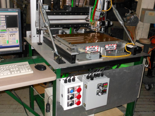
It can be accomplished but there's also a whole lot of other problems with a large 3-D printer. You would definitely need a heated enclosure for large prints which causes its own set of problems. You would have to build something super reliable because large prints are going to take multiple days to complete 24 hours a day here is a picture of mine this will give you an idea of the strength you need and mine is only 17" x 14" x 14" there are very few people that have built large machines which I would say work well
Edited 1 time(s). Last edit at 03/19/2014 12:51PM by cnc dick.
Edited 1 time(s). Last edit at 03/19/2014 12:51PM by cnc dick.
|
Re: Wallace Questions March 19, 2014 03:13PM |
Registered: 12 years ago Posts: 258 |
Pointing this toward the wiki:
[reprap.org] has a link to a 1m^3 LeBigRep with a video, and a few other larger machines and discussions.
[reprap.org] has a link to a 1m^3 LeBigRep with a video, and a few other larger machines and discussions.
|
Re: Wallace Questions March 19, 2014 04:11PM |
Registered: 10 years ago Posts: 474 |
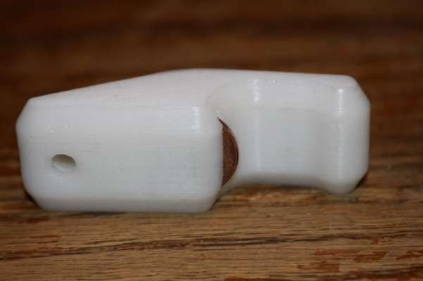
I guess it's all up to the individual to me all of those large ones you see there do not produce anywhere near quality prints and their is only one showing a large print and because there is no enclosure there is cracks in the print because of shrinkage. This is just a small test piece of bottle opener I printed on my machine look closely this is what I call acceptable
|
Re: Wallace Questions March 19, 2014 09:25PM |
Admin Registered: 11 years ago Posts: 3,096 |
cnc_dick do you ever take new pictures of your machine? Sorry, but I have seen those images I think around a hundred times 
It's okay you're showing your machine, and I mean no offense, but it's getting a bit repetitive and it couldn't hurt to put up some new images every now and then. It's also nice to see more of the machine instead of just the same picture all the time.
Sorry for the slight offtopic.
And Matidas, as far as my rod knowledge goes, if you get hard chrome 6mm smooth rods, they are very rigid and won't bent. You can get away with m6 threaded rods, they don't even have to be stainless as the smooth rods will provide the rigidity. Also the build volume is quite small so ... Oh wait.. Nevermind, I see you meant CM and not MM...

It's okay you're showing your machine, and I mean no offense, but it's getting a bit repetitive and it couldn't hurt to put up some new images every now and then. It's also nice to see more of the machine instead of just the same picture all the time.
Sorry for the slight offtopic.
|
Re: Wallace Questions March 19, 2014 10:02PM |
Registered: 10 years ago Posts: 474 |
Sorry no I can't post different pictures it's dismantled at the moment it has been moved from where I used to work to my cellar still in pieces didn't want to reassemble in case I found the job and needed to take it with me. And again I don't understand why you people get so upset obviously I was trying to show that you can get good quality from a large machine but it is not easy you need very strong components. You started to reply to the post but obviously you didn't pay attention he wants a very large printer. Do you know how many times I've seen pictures of the same type of 3-D printers on this forum and test prints all the same nobody complains about that
Edited 4 time(s). Last edit at 03/19/2014 10:17PM by cnc dick.
Edited 4 time(s). Last edit at 03/19/2014 10:17PM by cnc dick.
|
Re: Wallace Questions March 19, 2014 10:44PM |
Registered: 12 years ago Posts: 258 |
Quote
cnc dick
I guess it's all up to the individual to me all of those large ones you see there do not produce anywhere near quality prints and their is only one showing a large print and because there is no enclosure there is cracks in the print because of shrinkage. This is just a small test piece of bottle opener I printed on my machine look closely this is what I call acceptable
The bottle opener looks really good. How smooth is it and how big of a part can you make like that on your working machine? I can't quite tell from the other pic what sort of linear slides you are using, but it might be nice to know that you can print, for example, consistent 10 micron layers at 80mm/s over 433x355x355mm volume in a 55C enclosure with water cooling, aluminum ways and nylon gibs.
Perhaps Matidas has an application which requires the 1000x500x500mm mentioned. In which case, I expect that the Wallace would prove inadequate. Maybe a huge Wallace bolted to a Mendel90-like frame would be adequate for laying polyurethane foam with 10mm layers? You might be able to program out the sag in the G code.
We might be able to get great precision on small parts with stiff machines, but scaling up involves significant tradeoffs that depend on the application.
I thought it was interesting that the LeBigRap built the table upside down with the textured, tapering legs rising up into the build volume. I expect that that configuration would help avoid the shrinkage issues since the taller, less temperature controlled bits are smaller and disconnected from each other.
Edited 1 time(s). Last edit at 03/19/2014 10:44PM by DaveX.
|
Re: Wallace Questions March 19, 2014 11:52PM |
Registered: 10 years ago Posts: 474 |
The linear rails and bearings the THK brand I think they were HGR 25 If I remember correctly the perimeter was at 60 mm a second print area is 17" x 14" x 14" I can't show you any of the pictures of the prints that I did at work because they are proprietary obviously. I used to be a prototype technician for a large Pro audio company the biggest print I did was somewhere around 15" x 10" x 10" a quarter of a large high-frequency horn. I was going to build an enclosure that's permanently attached to machine with a door but never got that far I have a temporary one that you set over the whole top of the machine to do large prints and there is an air heater inside to. You need a heated environment do large prints. I'm in the process designing and putting together a small more portable one now hopefully in a month or so I should have it done
Edited 2 time(s). Last edit at 03/20/2014 12:16AM by cnc dick.
Edited 2 time(s). Last edit at 03/20/2014 12:16AM by cnc dick.
|
Re: Wallace Questions March 19, 2014 11:54PM |
Registered: 10 years ago Posts: 5 |
Thank you all for the replies. I was looking at using this for making boat sections for rather large model boats. I was wondering why it looked so simple, and know I know  Perhaps something like a rostock max would work printing the sections vertically. Has there been any work towards a dual extruder rostock?
 Perhaps something like a rostock max would work printing the sections vertically. Has there been any work towards a dual extruder rostock?
|
Re: Wallace Questions March 20, 2014 12:01AM |
Registered: 10 years ago Posts: 474 |
Quote
Matidas
Thank you all for the replies. I was looking at using this for making boat sections for rather large model boats. I was wondering why it looked so simple, and know I knowPerhaps something like a rostock max would work printing the sections vertically. Has there been any work towards a dual extruder rostock?
you can print in sections and glue together like I said in the post above that's what I used to do with large audio horns. So you really would not need a printer quite as large as you wanted but it has to be very sturdy and even the size of mine with a full-sized bed print you'd need a heated enclosure
Sorry, only registered users may post in this forum.


