A call for help/ideas to develop the Heated Bed
Posted by casainho
|
Candles to heat bed April 15, 2010 08:29AM |
Registered: 14 years ago Posts: 13 |
|
Re: A call for help/ideas to develop the Heated Bed June 15, 2010 09:10AM |
Registered: 14 years ago Posts: 356 |
Ok, NopHead went ahead and did build a Heated Room. I am sure Heated Bed discussion should now follow the Heated Room, I can't see both alone.
---
New cutting edge RepRap electronics, ARM 32 bits @ 100MHz runs RepRap @ 725mm/s:
[www.3dprinting-r2c2.com]
---
New cutting edge RepRap electronics, ARM 32 bits @ 100MHz runs RepRap @ 725mm/s:
[www.3dprinting-r2c2.com]
|
Re: A call for help/ideas to develop the Heated Bed June 15, 2010 11:41AM |
Registered: 13 years ago Posts: 1 |

|
Re: A call for help/ideas to develop the Heated Bed July 07, 2010 12:04PM |
Registered: 14 years ago Posts: 356 |

(Picture showing some parts of the Wade's Geared Nema 17 Extruder printed with PLA, 0.35mm nozzle, 0.325mm layer)
I went for a 0.35mm nozzle and then I started to need a real flat surface! I went for a piece of glass and it works perfectly!
Advantages of glass:
- comes really flat from factory;
- do not bend, which means the stores still sell them really flat. You will not be able to bend it, so it will always be flat;
- commonly found on local hardware stores and CHEAP! I bought one piece of 200x200x3mm for 0.5€!
- it is not a good dissipater as copper or aluminium, which takes a few more time to get hot but it also holds the temperature more time and there is not hot spots so easily like on copper or aluminium.
There was some users telling about glass a few times on this message - I am sorry for not trying it before.
As for heater, I am using nichrome wire, which I can find in local hardware store in many sizes and really cheap! I started to use a copper PCB board with nichrome wire glued on it and I quickly saw that copper had only hot spots near nichrome wire. Then I turned the PCB 180º and got the hot spread more linear. I did print a few parts on that way.
Finally I changed from 0.5mm nozzle (0.4mm layer) to 0.35mm nozzle (0.325 layer) and tried the glass in upper side of that PCB. The glass gets well hot after some time and the hot well spread. Also I got a really flat surface :-)
Edited 1 time(s). Last edit at 07/07/2010 12:10PM by casainho.
---
New cutting edge RepRap electronics, ARM 32 bits @ 100MHz runs RepRap @ 725mm/s:
[www.3dprinting-r2c2.com]
|
Re: A call for help/ideas to develop the Heated Bed August 20, 2010 11:51PM |
Do these carefully developed heated beds also improve print resolution?
I've just built a Makerbot and am having a difficult time even getting the material
to stick to itself. I think that I can adjust the temp in the software but I'd like to hear
the experiences you people might have had and would appreciate your words.
Thanks!
I've just built a Makerbot and am having a difficult time even getting the material
to stick to itself. I think that I can adjust the temp in the software but I'd like to hear
the experiences you people might have had and would appreciate your words.
Thanks!
|
Re: A call for help/ideas to develop the Heated Bed August 22, 2010 02:56PM |
Registered: 13 years ago Posts: 58 |
My two cents on the glass vs aluminum debate: (sorry Susan, I don't know the answers to your question)
Cast aluminum tooling plate can be purchased that comes very flat- no machining would be required.
The point of the heated bed is to stop warping and their seems to be two aspects to this. Heating the bed helps the first layer stick to the table. I see both glass and aluminum doing this equally well. The other goal is to get heat into the plastic in the hopes of maintaining an even temperature throughout. We don't want the bottom cooling while hot plastic is still being laid at the top. Aluminum is a much better conductor and will do a better job at getting heat into the plastic.
The wiki page brings up an issue of the bed expanding as it heats and 'bulging'. It won't bulge because the table is still allowed to expand in both the x and y directions without issue.
|
Re: A call for help/ideas to develop the Heated Bed August 23, 2010 12:26PM |
Registered: 13 years ago Posts: 81 |
|
Re: A call for help/ideas to develop the Heated Bed August 23, 2010 02:38PM |
Registered: 14 years ago Posts: 387 |
Quote
Thorp
Aluminum is a much better conductor and will do a better job at getting heat into the plastic.
I don't think so.
Consider a five-millimeter thick build plate, and a thirty-millimeter thick plastic object printed on top. Assume the bed's heating element is thermally well-bonded to the build plate.
Aluminum has a thermal conductivity of 250 W/mC. ABS has a thermal conductivity of 0.33 W/mC. Glass has a thermal conductivity of 1 W/mC. So Aluminum is 250 times better at conducting heat than glass.
Now examine the thermal resistance between the heating element and the top of the printed object.
For an aluminum build plate, the heat has to pass through 5 mm of aluminum and 30 mm of plastic. The thermal resistance is 0.005/250 + 0.030/0.33 = 0.090929 Km2/W. (Presenting the number here with an egregious number of significant figures; far more than I really should, but for good reason).
For a glass build plate, the heat has to pass through 5 mm of glass and 30 mm of plastic. The thermal resistance is 0.005/1 + 0.030/0.33 = 0.095909 Km2/W.
Comparing these values, there's only 5% more resistance in the case of the glass plate, even though aluminum is 250 times better at conducting heat than glass is. That's because in both cases, the thermal resistance from the plate itself is negligible compared with the thermal resistance of the plastic object being printed.
As for whether the heat conducts better into the bottom of the plastic object, in this case, the conductivity also does not matter. If the build plate is maintained at a controlled temperature, the bottom layer of plastic will also be at that temperature. Heat flow from one object to another only occurs when there is a difference in temperature, so as long as the build plate can replace the heat lost from the bottom layer of plastic (which is very small), there will be no issue. Large amounts of heat will not be conducted from the build plate into the plastic, so the resistance of the build plate is not very important. And in any event, the build plate temperature can be controlled to compensate.
|
Re: A call for help/ideas to develop the Heated Bed August 23, 2010 11:57PM |
Registered: 13 years ago Posts: 58 |
|
Re: A call for help/ideas to develop the Heated Bed August 24, 2010 12:46AM |
Registered: 14 years ago Posts: 387 |
Thanks  I always enjoy heat transfer problems. I get to apply what I learned in school! ^^
But yeah, that aside, I suppose it's a matter of what's available. Aluminum does have its advantages... it's lighter, for sure, so you can get a nice lightweight build platform from it, which is probably an important consideration for Mendel where the platform moves back and forth. And glass can be hard to work with without the right tools.
Edited 1 time(s). Last edit at 08/24/2010 12:49AM by jbayless.
I always enjoy heat transfer problems. I get to apply what I learned in school! ^^But yeah, that aside, I suppose it's a matter of what's available. Aluminum does have its advantages... it's lighter, for sure, so you can get a nice lightweight build platform from it, which is probably an important consideration for Mendel where the platform moves back and forth. And glass can be hard to work with without the right tools.
Edited 1 time(s). Last edit at 08/24/2010 12:49AM by jbayless.
|
Re: A call for help/ideas to develop the Heated Bed August 24, 2010 09:15AM |
Registered: 15 years ago Posts: 264 |
Conductivity will affect the amount of heat lost through the bottom of the bed, or the amount of insulation required to prevent heat lost through the bottom. If you have aluminum on top and plywood on the bottom, then most the heat will exit through the top. If you have glass on top and open air underneath, then most the heat will exit through the bottom. This means more power is required and also could jeopardize the integrity of the y-axis parts, especially if they are made of PLA.
Darwin clone, Gen 2 electronics, Arduino Duemilanove w/ AtMega328, 5D Firmware, Pinchwheel extruder
[www.codeerrors.com]
Darwin clone, Gen 2 electronics, Arduino Duemilanove w/ AtMega328, 5D Firmware, Pinchwheel extruder
[www.codeerrors.com]
|
Re: A call for help/ideas to develop the Heated Bed August 26, 2010 09:47AM |
Registered: 13 years ago Posts: 81 |
Got our first proof of concept up and running. Worked on the first try, seems to be great. Still working on wiring for now.
This one is 8"x8", but we should have a bigger one by next week....
(image links to higher-res)
This one is 8"x8", but we should have a bigger one by next week....

(image links to higher-res)
|
Re: A call for help/ideas to develop the Heated Bed August 28, 2010 06:27AM |
Registered: 13 years ago Posts: 19 |
I'm thinking about buying and making a reprap, and I'll probably want to make a heated bed for it too. Now I want to keep the costs rather low, and it seems to me that the temperature controller on the wiki would be rather expensive. So I came up with my own design. I only have some basic knowledge of electronics, so it could be that it would never work. So do you guys think this could work:
I would use insulated nichrome wire with a resistance of 23 ohm per meter, attached to an aluminium plate. I would divide the plate in 4 equal zones. That way I could save some electricity by only turning on the needed zones. The wire would be placed like shown in . So that's 4 wires of 33cm in each zone in parallel. 7,59 ohm per wire, so 1,9 ohm per zone, meaning 75W at 12V per zone and a total of 300W. Because there are 4 zones, each one can be placed on a different rail of the power supply, so it can handle that easily.
As the temperature controllers seem expensive (I couldn't find the components under 35€), I would use 12V, 8A dimmers, one per zone. Those are very cheap on ebay. By trial and error it should be possible to work out how much power is needed to keep the bed at the right temperature. Once I found how far I have to turn the button, I can mark it and it should stay at the right temperature without the need of a real temperature controller.
Does this sound like a good idea? Or should I just use one heating zone with a temperature controller instead of those dimmers?
I would use insulated nichrome wire with a resistance of 23 ohm per meter, attached to an aluminium plate. I would divide the plate in 4 equal zones. That way I could save some electricity by only turning on the needed zones. The wire would be placed like shown in . So that's 4 wires of 33cm in each zone in parallel. 7,59 ohm per wire, so 1,9 ohm per zone, meaning 75W at 12V per zone and a total of 300W. Because there are 4 zones, each one can be placed on a different rail of the power supply, so it can handle that easily.

As the temperature controllers seem expensive (I couldn't find the components under 35€), I would use 12V, 8A dimmers, one per zone. Those are very cheap on ebay. By trial and error it should be possible to work out how much power is needed to keep the bed at the right temperature. Once I found how far I have to turn the button, I can mark it and it should stay at the right temperature without the need of a real temperature controller.
Does this sound like a good idea? Or should I just use one heating zone with a temperature controller instead of those dimmers?
|
Re: A call for help/ideas to develop the Heated Bed August 28, 2010 09:40AM |
Admin Registered: 17 years ago Posts: 7,879 |
The bed temperature is normally controlled by the reprap firmware. All you need to do is add an extra thermistor and a big MOSFET to switch it.
I don't think a fixed power level will work well. The amount of heat lost will vary according to the bed movement and the size of the object being built on it. Also I use a different temperature for the first layer so mine needs to be under software control.
Separately controlled zones are not a good idea in my opinion. If you use a solid piece of aluminium then it will not have much temperature drop across it because it is such a good conductor. So if you only turned one heater on it would just heat up much more slowly. You would need some thermal insulation to isolate the zones. Also you don't just want to heat the area under the object, you want as much heat around it as you can get to prevent warping. With a moving table machine, the object moves through the air, so you want a buffer of hot air around it to avoid it moving into cold air.
Edited 1 time(s). Last edit at 08/28/2010 09:42AM by nophead.
[www.hydraraptor.blogspot.com]
|
Re: A call for help/ideas to develop the Heated Bed August 28, 2010 09:50AM |
Registered: 14 years ago Posts: 689 |
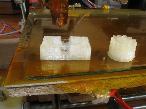
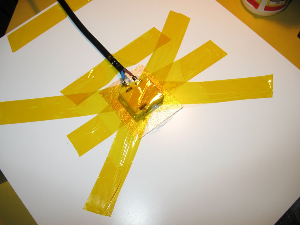
I've had this idea of a cheap heater for a while, and finally tried it it out. I salvaged the heating element from a $4.34 AC Coffee Warmer, and stuck it to the sweet Dibond FR bed from Clark with some thermal glue and a bit of kapton tape. I desoldered the original wires, as they felt a bit too flimsy, and ran it directly off 220v with a heavier gauge wire instead.
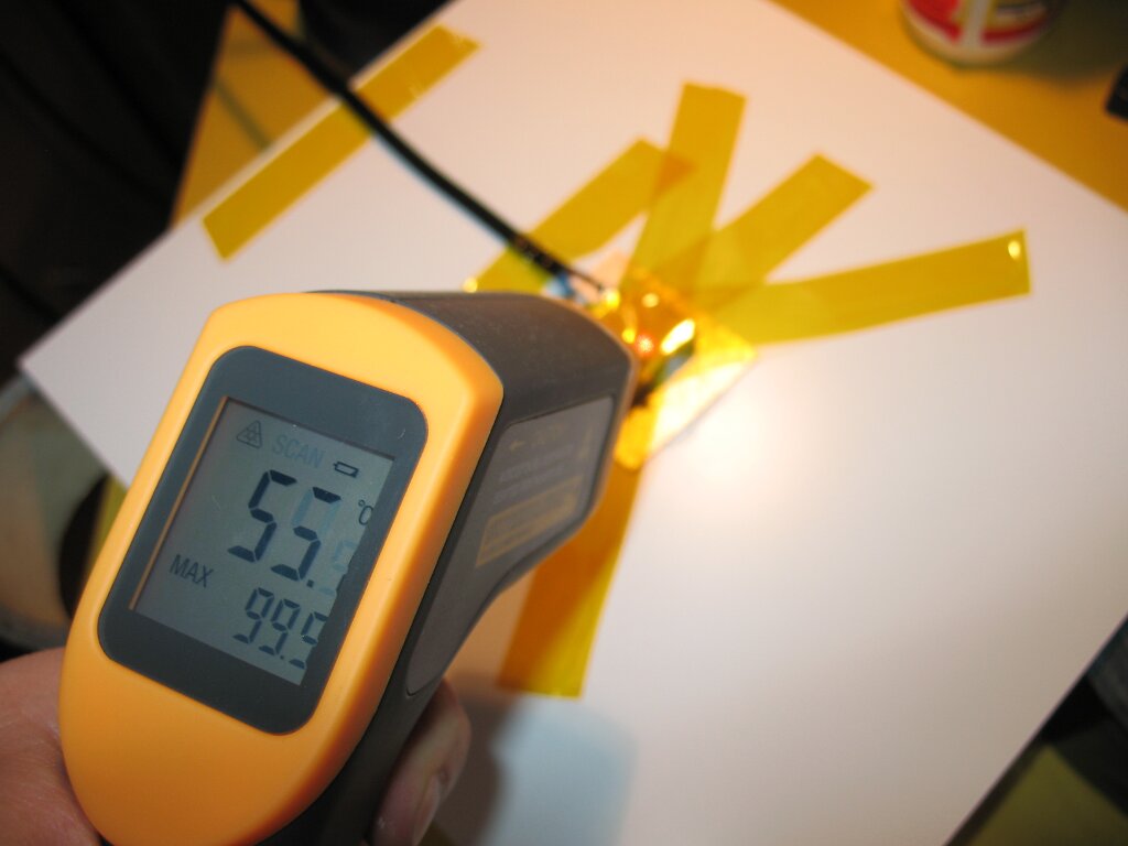
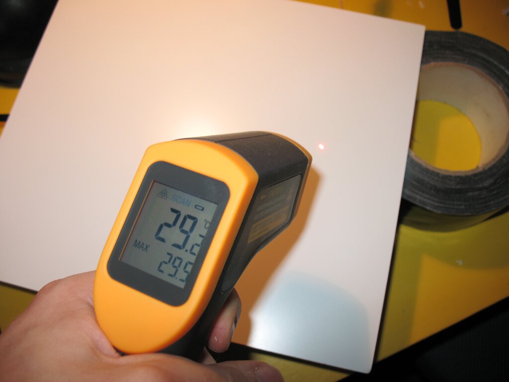
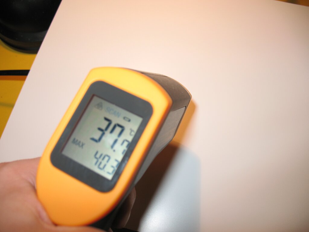
After about 10 minutes the ceramic part of the element measured between 70-80C, the metal connections on the heater measured more than 100C. The build plate had a hot spot with 40C, which is a 10C increase. (See attached pictures).
There was some sort of thermal pad or heat spreader in the coffee warmer, which I put on. Is it possible it might have worked against its purpose?
So, what do you guys think, is this worth pursuing at all? While adding more heaters is definitively needed, insulating the bottom will probably also make a good difference. It would be preferable to acquire only the heater elements, but I haven't found anything like this for sale. Then again, four of these coffee heaters will be $16.24 (with bulkrate enabled), while nine will be $33.51. And as a bonus for future projects, you get some sweet power switches with lights as well
Edited 2 time(s). Last edit at 08/28/2010 11:41AM by Nudel.
--
-Nudel
Blog with RepRap Comic
|
Re: A call for help/ideas to develop the Heated Bed August 28, 2010 10:16AM |
Registered: 13 years ago Posts: 19 |
Thanks nophead for preventing me from making that mistake.
Unfortunately I don't know anything about mosfets except that it is something with 3 connectors. So I have no clue on where to add the mosfet and thermistor to make the firmware control the temperatures. The wiki suggested to use an Arduino with an lcd etc. for controlling the temperature, so I thought that was the only option.
Is there a page that explains how to control the temperatures from the firmware without all those extras? And would that also be possible with the generation 6 electronics?
|
Re: A call for help/ideas to develop the Heated Bed August 28, 2010 11:50AM |
Admin Registered: 17 years ago Posts: 7,879 |
The details of how Adrian did it are here [reprap.org]. It is all integrated into the latest Reprap host and firmware I believe.
I don't know anything about gen 6 electronics, reprap is at gen 4 I believe, but as long as there is a spare analogue input and spare digital output then it can be made to work. I would be surprised if anybody would design new electronics without the ability to drive a heated bed.
[www.hydraraptor.blogspot.com]
|
Re: A call for help/ideas to develop the Heated Bed August 29, 2010 02:24PM |
Registered: 13 years ago Posts: 58 |
I'm quickly getting to the point where I'll be heating my build area... I've decided to go my own way with it as well...
I've bought a 150 watt IR lamp from the hardware store for 11 euros. I have a big roll of aluminum tape.
What I'll try first is layer some aluminum tape on my MDF build platform... stick a sheet of black card on top of it... and if acrylic will take it.. my acrylic build platform with kapton on top... If not, then I'll use a piece of glass.
From there, I'll put a 2mm layer of alumium on the bottom to spread the heat better, and use glass with kapton as my top surface.
I'll also restrict my heated area with the aluminum tape, and perhaps put a small fan blowing in from the back of the lamp.
A layer of flat black paint may prove better than the black card.
I'll be sure to blog what I discover, but my theory is the radiant heat will directly heat the build as well as the platform, which can only be a good thing for warping.
Issues I foresee are putting heat where I don't want it (aluminum tape will do a lot here to reflect away the radiation). Not enough of the power used for heating... Too much heat...
I may work out a computer controlled dimmer to liimit heat if I need to.
Al...
[araspitfire.blogspot.com]
|
Re: A call for help/ideas to develop the Heated Bed August 29, 2010 09:07PM |
Registered: 13 years ago Posts: 26 |
On my home-brew printer, I have a larger 6" x 7" build platform (about 150 x 175mm), so I had to make my own heated platform.
I used the following parts:
6" x 7" x 0.25" aluminum sheet
100W 4" x 5" silicone heater pad, 5 W/in^2, self adhesive backing, 120VAC (part# 35765K181 on McMaster.com, $27)
Four #6-32 male-female threaded aluminum hex standoffs (part# 93505A112 on McMaster.com, $0.44 each)
12" x 12" self-adhesive 0.002" thick Kapton Film (part# 2271K72 on McMaster.com, $15.46)
Solid State Relay (SSR), 10A 264VAC max out, 5-24VDC in. (part# G3NA-210B-DC5-24 at JameCo.com, $16)
3mm 100K thermistor, (http://store.makerbot.com/electronics/components.html, $5)
An AC power cable.
I drilled and tapped four holes in the back of the aluminum plate, and screwed the hex standoffs into it, to use for mounting the heated platform to the X-Y platform.
I drilled an additional 1/8" hole in the platform to mount the thermistor into, in the center of the platform. I wired and installed the thermistor, taping it into place with Kapton.
The heating pad was adhered the bottom of the aluminum plate, between the standoffs, over the thermistor hole. I used the 4" x 6" heater, but you can get them much larger.
I wired the heater pad up to power cord, with the output side of the SSR inline as a switch. The input of the SSR was wired to the extruder controller, to turn it on and off.
I cut the Kapton film to size, and adhered it to the top of the platform
Total cost: ~ $66 + the cost of the aluminum sheet and a few wires.
This reaches 110C in about 3 minutes. The Aluminum spreads the heat of the heater pad fairly well, but you may get hot spots if you use the 10W/in^2 heater variant.
|
Re: A call for help/ideas to develop the Heated Bed August 30, 2010 03:01AM |
Admin Registered: 17 years ago Posts: 1,791 |
RevarBat,
Neat!
http://reprap.org/wiki/RevarBed
-Sebastien, RepRap.org library gnome.
Remember, you're all RepRap developers (once you've joined the super-secret developer mailing list), and the wiki, RepRap.org, [reprap.org] is for everyone and everything!
Neat!
http://reprap.org/wiki/RevarBed
-Sebastien, RepRap.org library gnome.
Remember, you're all RepRap developers (once you've joined the super-secret developer mailing list), and the wiki, RepRap.org, [reprap.org] is for everyone and everything!
|
Re: A call for help/ideas to develop the Heated Bed August 30, 2010 06:07AM |
Registered: 13 years ago Posts: 26 |
|
Re: A call for help/ideas to develop the Heated Bed August 31, 2010 09:56AM |
Registered: 13 years ago Posts: 58 |
Report on IR Radiant heat.
After getting some black construction paper to 100 deg C in less than a minute... I was worried about having too much heat with my 150W radiant heater bulb. Not the case as it turns out.
I bought some matt black high-temperature paint, cut a 2mm aluminium plate to my table size (30x24), wiped it and sprayed it black.
A couple hours later I rested it on my thermocouple, on my MDF build platform, and turned the light on it at a distance of about 30cm, normal to the surface.
The temperature under the plate topped out in about 8 minutes, at 77 deg C. I put a piece of glass on it, and when it took another 10 minutes to get back to 80 deg, I cancelled the operation, realizing that the top surface of the glass would be cooler than the plate anyways.
Next was this plate, with a layer of Kapton on top. The temperature quite quickly came up to 80 to 90 deg. C. The tape obviously absorbes the IR.
I decided to print a Wade's large gear, as I had printed one the night before on acrylic, mostly successfully, but with a bit of warp.
I positioned the light at a 45 deg. angle, aimed into the extruder's hot-end. Temperatures were still about 90ish in front of the extruder, as measured by my IR non-contact thermometer. (I checked with the heat-light off for a sec to be sure)
I couldn't get my ABS natural to stick to it, I even wiped it with acetone... Someone on IRC was talking about 'drymount' adhesive spray, which I had laying nearby.. so gave it a try in desperation.
Drymount worked great for getting the print to stick.
And the 80 - 90 deg C surface temperature, plus whatever the natural ABS makes internally, works for keeping the print straight.... where it's warm...
But the backside was cooler.. by quite a bit... and showed quite bad shrinking... even worse than my whole gear was exhibiting on acrylic for some reason.. I aborted the print when I saw the back lifting.
It's clear to me that to do this, would need 2 150 watt lights, front and back... resistive heat is starting to look pretty good to me.
I'll blog about it and provide photos later.
Al...
[araspitfire.blogspot.com]
|
Re: A call for help/ideas to develop the Heated Bed September 07, 2010 02:57PM |
Registered: 13 years ago Posts: 18 |
Hi Everyone.
Gona bounce this around as an idea. (Apologies if it's been discussed before)
Issue - Hot and Flat top, Cold underside
You also need to keep it fairly Thin.
I have thought about a Kapton / Copper circuit heater Vacuum Bonded to Glass.
That is gona cost a fortune to get made and you still need to insulate the bottom.
It's just not gona happen on the grounds of Cost.
So - another Idea.
A Plumbers heat mat is glass based cloth designed to prevent Torches scorching paint work.
I plan to weave nichrome wire into the Heat Mat surface and lay a Glass plate on top.
A Bit of MDF Underneath the mat and hey presto - we have a Hot top and cold underside.
The Mat costs £ 5.00 or so. A bit of glass and a bit of Uninsulated Nichrome wire.
total Cost: less than £10 UK.
I'm working on nice round numbers for the heater.
2 ohms for the heater @ 12 Volts = 72 watts. That should be plenty.
( No I have not done the thermal calculations )
Comments welcome.
ParCan
|
Re: A call for help/ideas to develop the Heated Bed September 08, 2010 01:43PM |
Registered: 13 years ago Posts: 18 |
Hi
Done some more work on this idea.
I have some constantine ( Copper nickle ) Wire.
The bed is 200 mm X 200 mm
600 mm of my wire = 3 ohms
I can run that up and down the Mat 3 times with 8 mm or so spacings. ( 24 mm X 200 mm of bed area )
That's handy because it means I can have the + and - connections either side of the bed.
4 strips in paralell ( 96 mm width ) = 0.75 ohms.
Add a 2nd strip and wire them in series = 1.5 ohms = 100 w at 12 V ( or there abouts ) and I have a viable heater mat.
Or do i ?
ParCan
|
Re: A call for help/ideas to develop the Heated Bed September 08, 2010 01:56PM |
Registered: 13 years ago Posts: 19 |
Never mind, I can't read... viable and variable are different words. Sorry.
Edited 3 time(s). Last edit at 09/08/2010 02:06PM by tman.
my blog: [reprap.tman.be]
Edited 3 time(s). Last edit at 09/08/2010 02:06PM by tman.
my blog: [reprap.tman.be]
|
Re: A call for help/ideas to develop the Heated Bed September 08, 2010 02:00PM |
Admin Registered: 17 years ago Posts: 7,879 |
100W is probably the minimum you can get away with and have a reasonable warm up time.
My worry with constantine woven into a good insulator like that is that it may well get red hot and crack the glass. I think I read somebody's blog recently where exactly that happened.
Perhaps a better scheme would be to bond a thin sheet of aluminium to the glass with silicone to spread the heat and fasten the contantine on with Kapton tape as described here : http://reprap.org/wiki/Mendel_heated_bed
You could place the mat underneath for insulation. That will speed up the warm up time and reduce the power consumption. I prefer to just have an air gap under my bed so that I can cool it down quickly with a fan.
[www.hydraraptor.blogspot.com]
|
Re: A call for help/ideas to develop the Heated Bed September 09, 2010 03:43PM |
Registered: 13 years ago Posts: 18 |
Thanks for your comments nophead.
I have decided to try and run with the basis of my idea.
I got the mat from a local Plumbers. £ 2.50 UK
Glass was free - an offcut from the local glass shop.
I bought a fresh roll of heater wire from Maplin. £ 6.49 UK
I'll blog the build at: [parcansreprap.blogspot.com]
I have decided to try and run with the basis of my idea.
I got the mat from a local Plumbers. £ 2.50 UK
Glass was free - an offcut from the local glass shop.
I bought a fresh roll of heater wire from Maplin. £ 6.49 UK
I'll blog the build at: [parcansreprap.blogspot.com]
|
Re: A call for help/ideas to develop the Heated Bed September 11, 2010 10:58AM |
Registered: 13 years ago Posts: 18 |
I built the bed.
With 1.5 ohms @ 12 V it warmed up to about 70 C and that was about it in still air.
Added in pair of heater wires and got ti to 85 C
2 more pairs were added so the Resistance was around 1 ohm which is hitting the top of my Power supply. (15 Amps)
I got the bed to about 120 C and just as Nophead suggested I cracked the galss.
This method is Viable for PLA at 50 - 60 C but not for ABS which people tell me needs 110 C.
My blog is at: [parcansreprap.blogspot.com] with a few photo's
|
Re: A call for help/ideas to develop the Heated Bed September 11, 2010 01:05PM |
Registered: 14 years ago Posts: 387 |
|
Re: A call for help/ideas to develop the Heated Bed September 22, 2010 02:54AM |
Registered: 13 years ago Posts: 23 |
Does anybody know what the resistance(Ohms) should be for a 12in x 12in copper pcb traced heater platform should be? using 12v psu from makerbot (12v 11A, 400watt max)
I just tried today, and made a pattern and engraved it on a 12in x 12in pcb and it came out just like I was hoping at 3ohms (3.3 ohms or so really) and I thought that I needed 2-3 ohms resistance but then I hooked it up directly to the 12v and it only got to 45C or so and that took half an hour >.> My math is kind of weak... but from what I've read so far to reach the desired 120C for ABS I should be looking for how many watts?
Do I need to lower the resistance to only 1ohm?
12v / 1ohm = 12amp....
12amp x 12v = 144 watts
and 120+ watts or so will become 120C ? is this correct? o__O'
here is my first attempt (failed)
I used a laser thermometer to watch it go from 26C to about 41C...i got bored of that though and just put the aluminum plate over it. It is not touching the wood underneath or the aluminum plate above but it is closer to the aluminum... the aluminum is 14"x14" and I saw it go to 40C or so...but when i shined the laser underneath in between the copper pcb and the aluminum...it was in the 51-52C that is why I am just rounding it and saying it got to 45C or so.... but I still wanted to go to 120C so do I just lessen the length of the pattern by a third? and try and go to only 1ohm?
please help. thanks
I just tried today, and made a pattern and engraved it on a 12in x 12in pcb and it came out just like I was hoping at 3ohms (3.3 ohms or so really) and I thought that I needed 2-3 ohms resistance but then I hooked it up directly to the 12v and it only got to 45C or so and that took half an hour >.> My math is kind of weak... but from what I've read so far to reach the desired 120C for ABS I should be looking for how many watts?
Do I need to lower the resistance to only 1ohm?
12v / 1ohm = 12amp....
12amp x 12v = 144 watts
and 120+ watts or so will become 120C ? is this correct? o__O'
here is my first attempt (failed)

I used a laser thermometer to watch it go from 26C to about 41C...i got bored of that though and just put the aluminum plate over it. It is not touching the wood underneath or the aluminum plate above but it is closer to the aluminum... the aluminum is 14"x14" and I saw it go to 40C or so...but when i shined the laser underneath in between the copper pcb and the aluminum...it was in the 51-52C that is why I am just rounding it and saying it got to 45C or so.... but I still wanted to go to 120C so do I just lessen the length of the pattern by a third? and try and go to only 1ohm?
please help. thanks


Sorry, only registered users may post in this forum.