McWire Successor
Posted by sircastor
|
Re: McWire Successor March 27, 2010 10:31AM |
Registered: 14 years ago Posts: 581 |
I love the Delta bot you linked, but you have to remember, accuracy is what makes or breaks any Cartesian robot, and the Deltas make accuracy more challenging.
For Example, your typical Mendel peice has around 10-100 thousand lines of Gcode, each with a very specific number of 2 degree steps on all 3 axises. If in those thousands of lines of gcode you loose or overshoot even 1 step, the whole part will be visibly flawed. 3-4 and the part will likely be mechanically useless.
The Delta Robots suffer from the fact the motor sits at the fulcrum of each of the axises, requiring each axis to use it's holding torque to simply keep the head in place against gravity & the motion of the other axes. In a screw or belt drive the the motors only need hold against a much less aggressive force from the 2 other axes, and almost no holding against gravity.
Delta robots are a great research project, but I don't really see any advantages for this apliticaltion, besides the fact that they look freekin awesome.
repraplogphase.blogspot.com
|
Re: McWire Successor March 27, 2010 04:00PM |
Registered: 14 years ago Posts: 105 |
I see what you're saying, although in the specific robot I've linked to's case: the hobby servos I've played with seem to have decent holding torque simply as a result of the high gear ratio.
I can understand why there is a potential for cumulative error, however since the servo's themselves have potentiometer closed loop feedback, I'm hoping that the PID controller's acceptable error will be accurate enough for the intended purpose, and will manifest itself as noise rather than the cumulative error as you would see with missed steps on a stepper.
Because of the incredible potential of this avenue,($70 3 axis platform with high print speeds) I'd like to measure the inaccuracies and see if I can pull them out of the robot six sigma style.
Does anyone know of someone who has successfully written inverse kinematics code to control a delta bot/tripod in EMC2? (Other than FESTO I mean.)
Edited 1 time(s). Last edit at 03/27/2010 04:03PM by JohnnyCooper.
|
Re: McWire Successor March 29, 2010 07:15PM |
Registered: 14 years ago Posts: 5 |
Good news! My mock up of a belt driven McWire is done. Just waiting on bigger motors to finish it. Let me know what you think or if you have any suggestions.
[Shayfir.blogspot.com]
[Shayfir.blogspot.com]
|
Re: McWire Successor March 29, 2010 08:16PM |
Registered: 14 years ago Posts: 92 |
Arvin Wrote:
-------------------------------------------------------
>
> I bought some 50lb test braded fishing line. No
> luck. It started out great but seemed to flatten
> and then rolled up on the other layers. Still
> worked but the steps would not be the same length
> for those versus the lower layer.
>
> My next thought is kite string. I'm worried it
> will do the same thing. Mayb I just need to find a
> source for really thin steel cable. Did some
> searching earlier with no luck. I'll try again.
> Arvin
I gave it some thought a while ago while designing a cable drive. If the cable has multiple wraps around the capstan, and the capstan is winding on/off a screw of suitable pitch, advancing/withdrawing, it should allow the cable to wind on/off in an involute manner.
[forums.reprap.org]
Edited 1 time(s). Last edit at 03/29/2010 08:19PM by murrayd.
|
Re: McWire Successor March 30, 2010 12:27PM |
Registered: 14 years ago Posts: 380 |
murrayd, nice idea! If you can screw the middle of the cable down, and still have enough around the threaded rod to handle the full range of motion, you will get virtually zero slip.
A second way to do this have a guide bar with two well spaced holes. The cables go through the holes, and the guide bar is driven left and right by a thread drive running of the drive rod. This way, the spacing is more assured, since it is still possible to jump threads at the extreme ends without the moving guide holes. I will see if I can draft a drawing.
drawing.pdf
EDIT:
After looking at my drawing (sorry it is stuck in pdf), I can see that a much simpler solution is to combine both methods. Use a threaded rod to hold the cable, but have a "c" shaped piece of metal that is threaded to slid up and down the rod as it rotates, and has two openings for the cables to go through so that it winds even on and off the threaded rod. No need for a gear drive. In fact, the next step is to put the motor on a slide, and mount the "c" shaped block to the platform, so that the openings for the cables to come in and out does not move, but the motor moves left and right as it winds first one way then the other. 4 roller bearings at 45 degrees in angled slots would allow it to slide easily without the motor moving or flopping around.
Mike
Edited 2 time(s). Last edit at 03/30/2010 04:20PM by rocket_scientist.
Team Open Air
Blog Team Open Air
rocket scientists think LIGHTYEARS outside the box!
|
Re: McWire Successor March 30, 2010 07:44PM |
Registered: 15 years ago Posts: 59 |
Some kind of simple position measuring system, like the opto strip and quadrature sensor that can be scavenged in yard sale inkjet printers, can cover a multitude of sins, like slipping cables, and certainly the nonlinearity caused by cable winding onto a drum or cable stretching.
fdavies
fdavies
|
Re: McWire Successor March 30, 2010 08:21PM |
Registered: 14 years ago Posts: 380 |
|
Re: McWire Successor March 31, 2010 06:33AM |
Registered: 15 years ago Posts: 59 |
If you lift the front lid of the printer (as if to change the cartridges), you will often see a grey plastic strip. It is grey because of the large number of tiny stripes. You should take apart the printer to get it, and you should use the sensor from the same machine. The data sheets for the sensors imply that the exact spacing of the stripes is important, and I have seen different spacings on different machines.
The encoder outputs are usually preconditioned in the encoder, so they come out as a digital signal ready to go into an arduino.
There is usually a timing belt and DC motor in the printer, too. Get those for future use. Also, watch out for stray ink! People often get rid of their printers because they have become messy.
fdavies
|
Re: McWire Successor March 31, 2010 10:35PM |
Registered: 14 years ago Posts: 5 |
My improved version of McWire is pretty much complete. I converted the screw drives to belt drives and added a heated bed. I have to re burn the bootloader though unless anyone has any suggestions as to why my Makerbot extruder controller is freaking out and won't allow the extruder motor to stop. Anyway, check out the improved McWire on my blog and let me know what you think.
[Shayfir.blogspot.com]
[Shayfir.blogspot.com]
|
Re: McWire Successor April 01, 2010 12:19PM |
Registered: 16 years ago Posts: 169 |
@Shayfir-Very nice McWire build. Looking forward to your first print. How much did the belts and pulleys cost?
-------------------------------
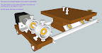
I've been slow to use the cable drive I've been working on because the 1/32" cable I ordered runs up over the other windings or runs over to the edge and then winds over the previous windings. The cable is stiff but does work. When you're winding it don't let go! Rats nest! Looks good and works well while I'm twisting it on and off by hand.
My analysis of the problem/s is the capstan is not perpendicular to the platforms travel and not level.
I've designed a rather complicated method to be able to adjust EVERYTHING!
Using some 1 1/2" pipe with holes drilled and tapped to use bolts at three equal spaces around some bearings I think I should be able to tweak it till it's just right. There are several diy cnc builds that do this.
Now gotta build one to see.
[picasaweb.google.com]
The sketchup file is here:
[dl.dropbox.com]
-------------------------------
I've been slow to use the cable drive I've been working on because the 1/32" cable I ordered runs up over the other windings or runs over to the edge and then winds over the previous windings. The cable is stiff but does work. When you're winding it don't let go! Rats nest! Looks good and works well while I'm twisting it on and off by hand.
My analysis of the problem/s is the capstan is not perpendicular to the platforms travel and not level.
I've designed a rather complicated method to be able to adjust EVERYTHING!
Using some 1 1/2" pipe with holes drilled and tapped to use bolts at three equal spaces around some bearings I think I should be able to tweak it till it's just right. There are several diy cnc builds that do this.
 |
| From reprap |
Now gotta build one to see.
[picasaweb.google.com]
The sketchup file is here:
[dl.dropbox.com]
|
Re: McWire Successor April 01, 2010 12:31PM |
Registered: 14 years ago Posts: 5 |
I ordered the belts and pulleys from McMaster-Carr
5 ft 7959K24
4 x 57105K11
Total was $38.70...pulleys were expeeensive. I have to find a way to make them.
This discussion over a cable drive system seems very promising cost-wise.
[Shayfir.blogspot.com]
5 ft 7959K24
4 x 57105K11
Total was $38.70...pulleys were expeeensive. I have to find a way to make them.
This discussion over a cable drive system seems very promising cost-wise.
[Shayfir.blogspot.com]
|
Re: McWire Successor April 01, 2010 01:31PM |
Registered: 14 years ago Posts: 28 |
JohnnyCooper Wrote:
-------------------------------------------------------
> I see what you're saying, although in the specific
> robot I've linked to's case: the hobby servos I've
> played with seem to have decent holding torque
> simply as a result of the high gear ratio.
>
> I can understand why there is a potential for
> cumulative error, however since the servo's
> themselves have potentiometer closed loop
> feedback, I'm hoping that the PID controller's
> acceptable error will be accurate enough for the
> intended purpose, and will manifest itself as
> noise rather than the cumulative error as you
> would see with missed steps on a stepper.
>
> Because of the incredible potential of this
> avenue,($70 3 axis platform with high print
> speeds) I'd like to measure the inaccuracies and
> see if I can pull them out of the robot six sigma
> style.
>
[objects.reprap.org]
[forums.reprap.org]
> Does anyone know of someone who has successfully
> written inverse kinematics code to control a delta
> bot/tripod in EMC2? (Other than FESTO I mean.)
[forums.trossenrobotics.com]
|
Re: McWire Successor April 01, 2010 04:35PM |
Registered: 15 years ago Posts: 264 |
I've found that the opto-sensors in use for the Mendel can see through blank paper, but can't see through paper I have printed black with an inkjet printed. This makes it easy to make custom encoders.
Darwin clone, Gen 2 electronics, Arduino Duemilanove w/ AtMega328, 5D Firmware, Pinchwheel extruder
[www.codeerrors.com]
Darwin clone, Gen 2 electronics, Arduino Duemilanove w/ AtMega328, 5D Firmware, Pinchwheel extruder
[www.codeerrors.com]
|
Re: McWire Successor April 02, 2010 04:41PM |
Registered: 14 years ago Posts: 248 |
mccoyn Wrote:
-------------------------------------------------------
> I've found that the opto-sensors in use for the
> Mendel can see through blank paper, but can't see
> through paper I have printed black with an inkjet
> printed. This makes it easy to make custom
> encoders.
For linear encoding you could theoretically use of the online barcode generators.
|
Re: McWire Successor June 19, 2010 05:40PM |
Registered: 13 years ago Posts: 117 |
I didn't read the whole thread but I wanted to report about my experiences with my WolfStrap build because I think it's the best concept for a cost-effective and accessible RepStrap.
I used Wolfgang's instructions for building the frame and the axis. This was incredibly easy. Initially I wanted to use M8 threaded bar for the drives because I wanted to use as much re-usable stuff as possible but Wolfgang convinced me during a long phone call that threaded bar is painfully slow. So I got the Mendel belt kit, a handful of 608 bearings (both will be need in the Mendel anyways) and found some T5x16 pulleys at the local electronics store (Conrad).
After splitting the Mendel Z-Belt I used the 5mm portion as the Y-drive and the rest as X-drive because they're a good fit length-wise for the WolfStrap's dimensions. The Z-drive remains a M8 threaded bar.
I used large metal corner braces, M8 bolts, 608 bearings and large washers to build idlers for the belts. The same corner braces were a perfect fit as stepper motor mounts (after 3 minutes with a Dremel cutting disc).
Overall the build was not very complicated and dead-cheap. Here is a rough breakdown of the costs:
20€ - all extruder hot end parts at grrf.de. lots of NiCr and Kapton left
30€ - RP parts for Wade's geared extruder bought from Wolfgang
20€ - Mendel belt kit from grrf.de
60€ - 3 NEMA17 steppers for the axis from grrf.de (they're expensive!!)
10€ - 1 NEMA17 stepper for the extruder from ebay
16€ - 2 T5x16 pulleys at Conrad electronics (incredibly expensive!!)
6€ - 10 608 bearings from ebay (used only 7 of them)
about 70€ for all the wood, slides, bolts, metal corner braces, threaded bar and screws with lot's of leftovers
------
round about 250€ total for the whole build of the bot and extruder. Much of the stuff I bought could've been cheaper but I was too lazy to search.
Add your choice of electronics and you're good to go. I went with techzonecom.com (which are still not here after 3 weeks ).
).
I believe this is the most cost-effective method to get your Mendel. Everyone who can mount a bookshelf and build an Ikea bed should be able to do this. For the construction you only need normal household tools except for the wood pieces and extruder drive bolt.
If you don't have your own circular saw and drill-press for the wood I think you can assume that there's a carpenter somewhere near you who can do it for you.
The filament drive bolt for Wade's extruder is easy to make if you have a drill-press with XY-table, otherwhise you can switch to Adrian's geared extruder.
I have taken lot's of pics during all stages of the build. I started to edit the German WolfStrap wiki page to include my experiences. I'll update the english one as well if I find the time.
I used Wolfgang's instructions for building the frame and the axis. This was incredibly easy. Initially I wanted to use M8 threaded bar for the drives because I wanted to use as much re-usable stuff as possible but Wolfgang convinced me during a long phone call that threaded bar is painfully slow. So I got the Mendel belt kit, a handful of 608 bearings (both will be need in the Mendel anyways) and found some T5x16 pulleys at the local electronics store (Conrad).
After splitting the Mendel Z-Belt I used the 5mm portion as the Y-drive and the rest as X-drive because they're a good fit length-wise for the WolfStrap's dimensions. The Z-drive remains a M8 threaded bar.
I used large metal corner braces, M8 bolts, 608 bearings and large washers to build idlers for the belts. The same corner braces were a perfect fit as stepper motor mounts (after 3 minutes with a Dremel cutting disc).
Overall the build was not very complicated and dead-cheap. Here is a rough breakdown of the costs:
20€ - all extruder hot end parts at grrf.de. lots of NiCr and Kapton left
30€ - RP parts for Wade's geared extruder bought from Wolfgang
20€ - Mendel belt kit from grrf.de
60€ - 3 NEMA17 steppers for the axis from grrf.de (they're expensive!!)
10€ - 1 NEMA17 stepper for the extruder from ebay
16€ - 2 T5x16 pulleys at Conrad electronics (incredibly expensive!!)
6€ - 10 608 bearings from ebay (used only 7 of them)
about 70€ for all the wood, slides, bolts, metal corner braces, threaded bar and screws with lot's of leftovers
------
round about 250€ total for the whole build of the bot and extruder. Much of the stuff I bought could've been cheaper but I was too lazy to search.
Add your choice of electronics and you're good to go. I went with techzonecom.com (which are still not here after 3 weeks
).I believe this is the most cost-effective method to get your Mendel. Everyone who can mount a bookshelf and build an Ikea bed should be able to do this. For the construction you only need normal household tools except for the wood pieces and extruder drive bolt.
If you don't have your own circular saw and drill-press for the wood I think you can assume that there's a carpenter somewhere near you who can do it for you.
The filament drive bolt for Wade's extruder is easy to make if you have a drill-press with XY-table, otherwhise you can switch to Adrian's geared extruder.
I have taken lot's of pics during all stages of the build. I started to edit the German WolfStrap wiki page to include my experiences. I'll update the english one as well if I find the time.
|
Re: McWire Successor June 19, 2010 08:30PM |
Registered: 13 years ago Posts: 7,616 |
Fully agreed, Tiberius. I did the same decision, most of the practical work has to be done, yet.
BTW., I'll use threaded bars intentionally, as I expect to keep the machine with a Dremel in the toolstock. Some 600 mm/minute isn't that bad for milling.
BTW., I'll use threaded bars intentionally, as I expect to keep the machine with a Dremel in the toolstock. Some 600 mm/minute isn't that bad for milling.
| Generation 7 Electronics | Teacup Firmware | RepRap DIY |
|
Re: McWire Successor June 20, 2010 05:52AM |
Registered: 13 years ago Posts: 117 |
|
Re: McWire Successor June 25, 2010 05:09AM |
Registered: 13 years ago Posts: 7,616 |
The Wiki page shows a isometric drawing which is obviously made from a 3D model. Is this model available somewhere? I'd like to refine it for my purposes.
Thanks,
Markus
Thanks,
Markus
| Generation 7 Electronics | Teacup Firmware | RepRap DIY |
|
Re: McWire Successor June 25, 2010 07:39AM |
Registered: 13 years ago Posts: 117 |

Sorry, only registered users may post in this forum.