Wiring 5 wire Opto Endstop to Ramps 1.4
Posted by runninfarmer
|
Wiring 5 wire Opto Endstop to Ramps 1.4 November 02, 2014 09:51PM |
Registered: 10 years ago Posts: 105 |
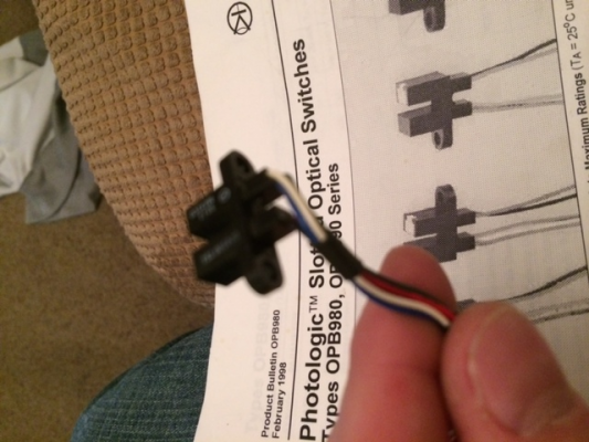
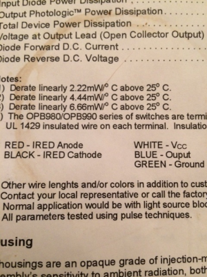
I'm converting an old lab instrument to a printer and want to use the current opto endstops on the machine. They're 5 wire photologic slotted opto switches, series OPB980. The question I have is, since there are only 3 connections to the ramps board, which wires do I connect to it? Will these switches even work with it? Thanks for the help! Here are a couple pics:
Edited 2 time(s). Last edit at 11/02/2014 09:53PM by runninfarmer.
Edited 2 time(s). Last edit at 11/02/2014 09:53PM by runninfarmer.
|
Re: Wiring 5 wire Opto Endstop to Ramps 1.4 November 02, 2014 11:03PM |
Registered: 10 years ago Posts: 1,401 |
You actually need to wire all, but white,blue and green are the main ones to the board, and should go:white,green and blue. Now the white powers "assuming" the receiver part of the switch and red and black the emitter, so "don't blame me if not right " but black and green together because they are ground, and red and white for + side but i don't know if voltage requirements are the same? (Not shown in the photos)
|
Re: Wiring 5 wire Opto Endstop to Ramps 1.4 November 03, 2014 03:51PM |
Registered: 10 years ago Posts: 105 |
Would I just solder the red/white together and solder the black/green together? Does that mean the red and black are constantly emitting and when something enters the slot, that sends the signal to the board? Sorry I'm a noob with this stuff. Thanks for the help. It would really be nice to use the current endstop setup. I will start another thread dedicated to the conversion I'm doing once it's done.
|
Re: Wiring 5 wire Opto Endstop to Ramps 1.4 November 03, 2014 06:24PM |
Registered: 11 years ago Posts: 296 |
|
Re: Wiring 5 wire Opto Endstop to Ramps 1.4 November 03, 2014 07:26PM |
Registered: 10 years ago Posts: 341 |
Looking at this datasheet online (check to make sure this is yours) (optek), it says "Do not connect input diode directly to a voltage source without an external current limiting resistor." Which means you will need a resistor in series with the input diode.
According to the datasheet, the absolute max forward current in the diode is 40mA, so you want to be under that. The forward voltage is 1.7V (tested at iF=20mA) so aim for about 20mA.
To select the resistor, and using 5V from the RAMPS, you want the resistor to have 5-1.7=3.3V across it, and at 20mA you end up with (using V=IR) R=3.3/20m = 165. I think there is a 160 Ohm in the standard resistor values.
I have not used one of these, but judging by the datasheet it looks like VOut will output HIGH when unblocked and LOW when blocked.
*I've never used these before so check your datasheet and confirm before wiring it up!
|
Re: Wiring 5 wire Opto Endstop to Ramps 1.4 November 03, 2014 09:52PM |
Registered: 10 years ago Posts: 105 |
|
Re: Wiring 5 wire Opto Endstop to Ramps 1.4 November 03, 2014 11:07PM |
Registered: 10 years ago Posts: 1,401 |
|
Re: Wiring 5 wire Opto Endstop to Ramps 1.4 November 03, 2014 11:09PM |
Registered: 10 years ago Posts: 341 |
You will need to solder on a new resistor in series with the diode (i.e. only onto one of the wires, not both). For example, connect one end of resistor to 5V, then connect the other end of resistor to the anode of the IR diode then connect the IR diode cathode to the GND. Don't forget the diode is polarised, so it needs to be connected the right way.
Yeah, the 3 pins on ramps should be ok, since it has the 5V, Signal, and GND.
Yeah, the 3 pins on ramps should be ok, since it has the 5V, Signal, and GND.
Sorry, only registered users may post in this forum.

