Prusa i3 Print part is mirrored Help!!!
Posted by GOO2014
|
Prusa i3 Print part is mirrored Help!!! November 13, 2014 04:06AM |
Registered: 9 years ago Posts: 7 |
Hi
I really need help to fix my Prusa i3 printer. The objects are mirrored ( I think is the X axis). The only way I can print normal part is to use Cura and make X mirrored .
Is this hardware hardware or software fault?
Thank you.
#define TEMP_SENSOR_0 6
#define TEMP_SENSOR_1 0
#define TEMP_SENSOR_2 0
#define TEMP_SENSOR_BED 6
#define TEMP_RESIDENCY_TIME 10 // (seconds)
#define TEMP_HYSTERESIS 3 // (degC) range of +/- temperatures considered "close" to the target one
#define TEMP_WINDOW 1 // (degC) Window around target to start the recidency timer x degC early.
#define HEATER_0_MINTEMP 5
#define HEATER_1_MINTEMP 5
#define HEATER_2_MINTEMP 5
#define BED_MINTEMP 5
#define HEATER_0_MAXTEMP 280
#define HEATER_1_MAXTEMP 280
#define HEATER_2_MAXTEMP 280
#define BED_MAXTEMP 125
// Uncomment the following line to enable CoreXY kinematics
// #define COREXY
// corse Endstop Settings
#define ENDSTOPPULLUPS // Comment this out (using // at the start of the line) to disable the endstop pullup resistors
#ifndef ENDSTOPPULLUPS
// fine Enstop settings: Individual Pullups. will be ignord if ENDSTOPPULLUPS is defined
#define ENDSTOPPULLUP_XMAX
#define ENDSTOPPULLUP_YMAX
#define ENDSTOPPULLUP_ZMAX
#define ENDSTOPPULLUP_XMIN
#define ENDSTOPPULLUP_YMIN
//#define ENDSTOPPULLUP_ZMIN
#endif
#ifdef ENDSTOPPULLUPS
// #define ENDSTOPPULLUP_XMAX
// #define ENDSTOPPULLUP_YMAX
// #define ENDSTOPPULLUP_ZMAX
#define ENDSTOPPULLUP_XMIN
#define ENDSTOPPULLUP_YMIN
#define ENDSTOPPULLUP_ZMIN
#endif
// The pullups are needed if you directly connect a mechanical endswitch between the signal and ground pins.
const bool X_ENDSTOPS_INVERTING = false; // set to true to invert the logic of the endstops.
const bool Y_ENDSTOPS_INVERTING = false; // set to true to invert the logic of the endstops.
const bool Z_ENDSTOPS_INVERTING = false; // set to true to invert the logic of the endstops.
//#define DISABLE_MAX_ENDSTOPS
// For Inverting Stepper Enable Pins (Active Low) use 0, Non Inverting (Active High) use 1
#define X_ENABLE_ON 0
#define Y_ENABLE_ON 0
#define Z_ENABLE_ON 0
#define E_ENABLE_ON 0 // For all extruders
// Disables axis when it's not being used.
#define DISABLE_X false
#define DISABLE_Y false
#define DISABLE_Z false
#define DISABLE_E false // For all extruders
#define INVERT_X_DIR true // for Mendel set to false, for Orca set to true
#define INVERT_Y_DIR false // for Mendel set to true, for Orca set to false
#define INVERT_Z_DIR false // for Mendel set to false, for Orca set to true
#define INVERT_E0_DIR false // for direct drive extruder v9 set to true, for geared extruder set to false
#define INVERT_E1_DIR false // for direct drive extruder v9 set to true, for geared extruder set to false
#define INVERT_E2_DIR false // for direct drive extruder v9 set to true, for geared extruder set to false
// ENDSTOP SETTINGS:
// Sets direction of endstops when homing; 1=MAX, -1=MIN
#define X_HOME_DIR -1
#define Y_HOME_DIR -1
#define Z_HOME_DIR -1 // Bed home to top (0)
#define min_software_endstops false //If true, axis won't move to coordinates less than HOME_POS.
#define max_software_endstops true //If true, axis won't move to coordinates greater than the defined lengths below.
// Travel limits after homing
#define X_MAX_POS 200
#define X_MIN_POS 0
#define Y_MAX_POS 200
#define Y_MIN_POS 0
#define Z_MAX_POS 200
#define Z_MIN_POS 0
#define X_MAX_LENGTH (X_MAX_POS - X_MIN_POS)
#define Y_MAX_LENGTH (Y_MAX_POS - Y_MIN_POS)
#define Z_MAX_LENGTH (Z_MAX_POS - Z_MIN_POS)
// The position of the homing switches
//#define MANUAL_HOME_POSITIONS // If defined, MANUAL_*_HOME_POS below will be used
//#define BED_CENTER_AT_0_0 // If defined, the center of the bed is at (X=0, Y=0)
//Manual homing switch locations:
#define MANUAL_X_HOME_POS 0
#define MANUAL_Y_HOME_POS 0
#define MANUAL_Z_HOME_POS 0
//// MOVEMENT SETTINGS
#define NUM_AXIS 4 // The axis order in all axis related arrays is X, Y, Z, E
#define HOMING_FEEDRATE {50*60, 50*60, 50, 0} // set the homing speeds (mm/min)
// default settings
#define DEFAULT_AXIS_STEPS_PER_UNIT {79.77,79.43,394.61,180} // default steps per unit for ultimaker {78.7402,78.7402,200*8/3,760*1.1}920
#define DEFAULT_MAX_FEEDRATE {500, 500, 2, 25} // (mm/sec)
#define DEFAULT_MAX_ACCELERATION {150,150,10,150} // X, Y, Z, E maximum start speed for accelerated moves. E default values are good for skeinforge 40+, for older versions raise them a lot.
#define DEFAULT_ACCELERATION 150 // X, Y, Z and E max acceleration in mm/s^2 for printing moves
#define DEFAULT_RETRACT_ACCELERATION 150 // X, Y, Z and E max acceleration in mm/s^2 for r retracts
// Offset of the extruders (uncomment if using more than one and relying on firmware to position when changing).
// The offset has to be X=0, Y=0 for the extruder 0 hotend (default extruder).
// For the other hotends it is their distance from the extruder 0 hotend.
// #define EXTRUDER_OFFSET_X {0.0, 20.00} // (in mm) for each extruder, offset of the hotend on the X axis
// #define EXTRUDER_OFFSET_Y {0.0, 5.00} // (in mm) for each extruder, offset of the hotend on the Y axis
// The speed change that does not require acceleration (i.e. the software might assume it can be done instanteneously)
#define DEFAULT_XYJERK 20.0 // (mm/sec)
#define DEFAULT_ZJERK 0.4 // (mm/sec)
#define DEFAULT_EJERK 5.0 // (mm/sec)
|
Re: Prusa i3 Print part is mirrored Help!!! November 13, 2014 04:16AM |
Registered: 9 years ago Posts: 37 |
|
Re: Prusa i3 Print part is mirrored Help!!! November 13, 2014 06:49AM |
Admin Registered: 11 years ago Posts: 3,096 |
Quote
Hauser
it happened also to me when I set up my firmware..
try to change:
#define INVERT_X_DIR true
to
#define INVERT_X_DIR false
watch out because the home position for your x axis will be on the oposite side.
I don't know if it's the best way to solve it, but it's how I did it.
Yes, this is the best way to solve it!
Other workaround is to disconnect the machine from power (VERY IMPORTANT) and to simply put the stepper motor connector in backwards. This way all the motor's movements are reversed

But doing it in the firmware is a way better solution i.m.o. You can also set the direction for the endstops that way so you don't have to change it physically.
http://www.marinusdebeer.nl/
|
Re: Prusa i3 Print part is mirrored Help!!! November 13, 2014 04:13PM |
Registered: 9 years ago Posts: 7 |
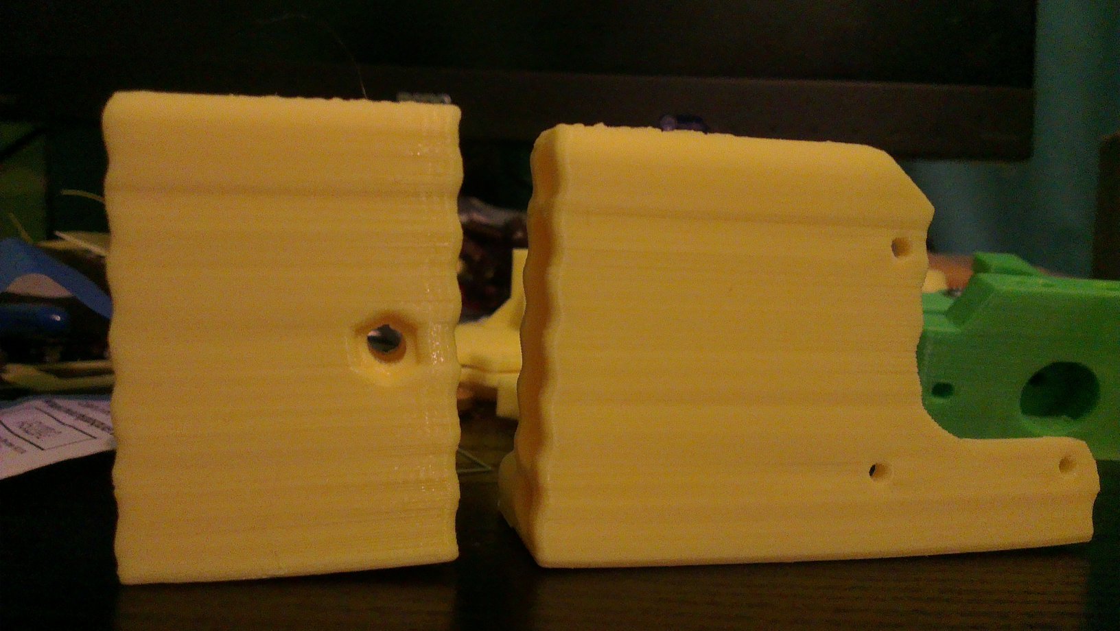
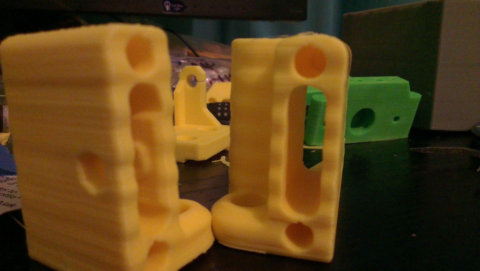
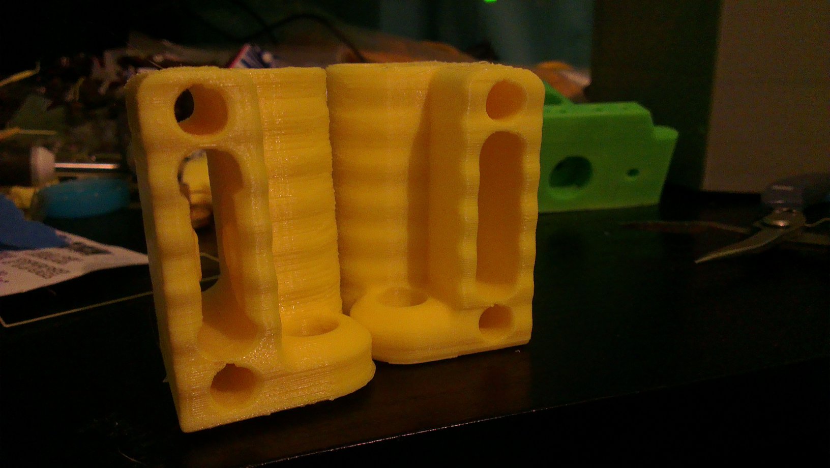
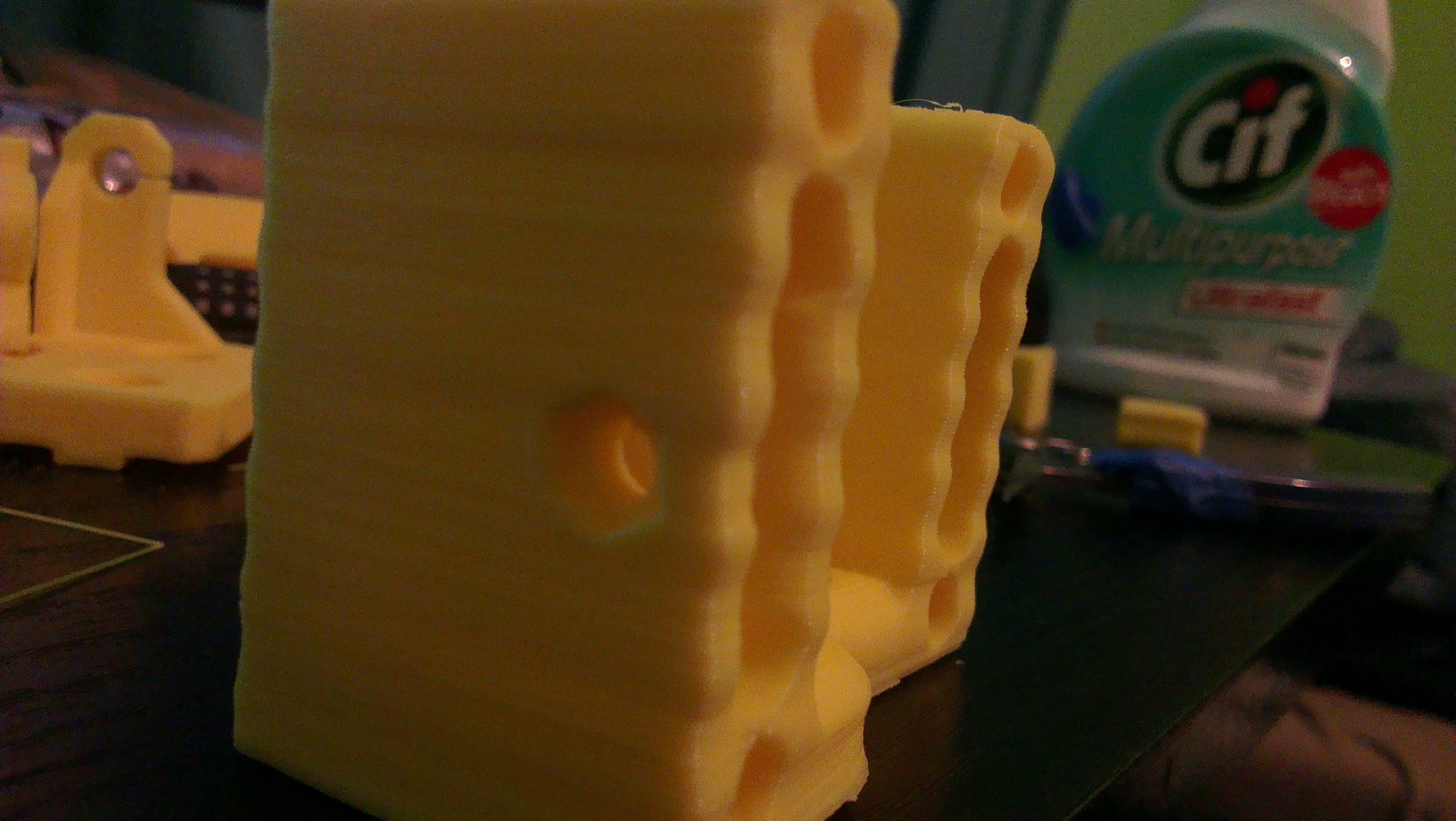
Thank you guys. I will try to make the changes and let you know. it's bed time for me now (long day at work) BTW, i'm getting wave edges on print and not straight. Is this because of X axis (i'm not using bearing holder)?
BTW, i'm getting wave edges on print and not straight. Is this because of X axis (i'm not using bearing holder)?
|
Re: Prusa i3 Print part is mirrored Help!!! November 14, 2014 11:27AM |
Registered: 10 years ago Posts: 10 |
|
Re: Prusa i3 Print part is mirrored Help!!! November 14, 2014 08:36PM |
Registered: 9 years ago Posts: 7 |
Hi,
@ProtoLab3D, I fixed the wave edges on print. forum [forums.reprap.org]
I didn't get the chance to change the motor direction yet. Because i had bigger problem with the printer.
Thank you
@ProtoLab3D, I fixed the wave edges on print. forum [forums.reprap.org]
I didn't get the chance to change the motor direction yet. Because i had bigger problem with the printer.
Thank you
Sorry, only registered users may post in this forum.