Soldering resistor onto A4988's ROSC pin
Posted by Ohmarinus
|
Re: Soldering resistor onto A4988's ROSC pin April 24, 2019 04:58AM |
Admin Registered: 13 years ago Posts: 7,001 |
|
Re: Soldering resistor onto A4988's ROSC pin April 24, 2019 04:42PM |
Admin Registered: 11 years ago Posts: 3,096 |
Just a side note, besides the sounds being way more bearable now, the machine also misses fewer steps. I printed out a test object that failed twice at the exact same point and caused my Y-axis to lose steps. The third time I printed it with the modification and it just pushed through 
http://www.marinusdebeer.nl/

http://www.marinusdebeer.nl/
|
Re: Soldering resistor onto A4988's ROSC pin April 24, 2019 06:30PM |
Registered: 5 years ago Posts: 2 |
Thanks for the comparison 
I tried this on my tevo mks base 1.4 8 bit board that has integrated a4982 drivers.Later I read about this mod is changing pwm in a way that is not optimal for 8bit boards. [hackaday.io]
I tried it out beacause my setup had really bad salmon skin effect and this can improve quality.
Did you see any difference in quality? Maybe the sensing resistors are also affecting the behavior of the steppere.
For me, it was similarly noisy after the mod. Also i heard more motor whining.
I have all metal frame, so that higly amplifies noises.
When I added noise dampers to the motors It made a much bigger difference. That is basicly two metal plate with scew holes and has rubber in between them.
I have this type, like this image shows [ae01.alicdn.com]
Edited 5 time(s). Last edit at 04/25/2019 09:03AM by azbest_hu.

I tried this on my tevo mks base 1.4 8 bit board that has integrated a4982 drivers.
I tried it out beacause my setup had really bad salmon skin effect and this can improve quality.
Did you see any difference in quality? Maybe the sensing resistors are also affecting the behavior of the steppere.
For me, it was similarly noisy after the mod. Also i heard more motor whining.
I have all metal frame, so that higly amplifies noises.
When I added noise dampers to the motors It made a much bigger difference. That is basicly two metal plate with scew holes and has rubber in between them.
I have this type, like this image shows [ae01.alicdn.com]
Edited 5 time(s). Last edit at 04/25/2019 09:03AM by azbest_hu.
|
Re: Soldering resistor onto A4988's ROSC pin April 25, 2019 04:24AM |
Admin Registered: 11 years ago Posts: 3,096 |
Quote
azbest_hu
Thanks for the comparison
I tried this on my tevo mks base 1.4 8 bit board that has integrated a4982 drivers. Later I read about this mod is changing pwm in a way that is not optimal for 8bit boards. [hackaday.io]
I tried it out beacause my setup had really bad salmon skin effect and this can improve quality.
Did you see any difference in quality? Maybe the sensing resistors are also affecting the behavior of the steppere.
For me, it was similarly noisy after the mod. Also i heard more motor whining.
I have all metal frame, so that higly amplifies noises.
When I added noise dampers to the motors It made a much bigger difference. That is basicly two metal plate with scew holes and has rubber in between them.
I have this type, like this image shows [ae01.alicdn.com]
Thanks for that link, it has some very interesting information. However, I do not see the relation that the mod is changing the pwm in a way that is not optimal for 8bit boards, could you explain it further? Maybe I am missing the point.
I assume you are talking about this part?
Quote
Back to the HR4988. I need to do some more active probing of this chip while driving a motor, particularly because my current probe has a bandwidth of 20 kHz and the PWM current control has a clock rate of ~32 kHz when RSOC is shorted to ground. When dealing with the current control, the HR4988/A4988 doesn't have the ability for a straight up fast decay mode. This is partially why in prior captures, the current fails to escape the windings and we begin missing microsteps when we try and go faster than ~50 mm/s. However, if you put a pull-down resistor between RSOC & ground, you can change the frequency of the PWM current control, but this is caused by adjusting the off time of the logic. With reduced off time, faster speeds can only be achieved through hardware means: "braking diodes". These are factors 3 & 4 that affect speed and resolution.
http://www.marinusdebeer.nl/
|
Re: Soldering resistor onto A4988's ROSC pin April 25, 2019 09:18AM |
Registered: 9 years ago Posts: 752 |
Not always, when the motion is at 45 degrees, only one stepper is used. I think rather corexy is weaker as it needs to move two axes with one stepper at 45 degrees angle movements.
Also, holding torque becomes important when one motor needs to stay put while the other moves. Some drivers can decrease the current when motion has stopped, this could be a problem if one motor pulls the other out of its holding position.
--
Kind regards
Imqqmi
NFAN CoreXY printer:
[reprap.org]
Also, holding torque becomes important when one motor needs to stay put while the other moves. Some drivers can decrease the current when motion has stopped, this could be a problem if one motor pulls the other out of its holding position.
Quote
Ohmarinus
Phase Resistance: 1.7 Ohm ± 10% (20º C)
So in theory, that should be close to 1.65 Ohms.
Oh, and they're 1.2A stepper motors. Properly running, not getting hot. I think CoreXY needs way less power to move the carriage, since the movements are always coordinated by two motors simultaneously.
--
Kind regards
Imqqmi
NFAN CoreXY printer:
[reprap.org]
|
Re: Soldering resistor onto A4988's ROSC pin April 25, 2019 09:24AM |
Registered: 9 years ago Posts: 752 |
I can't hear the difference with my tablet. Probably the automatic gain control on the phone afjusting to the sound level produced.
--
Kind regards
Imqqmi
NFAN CoreXY printer:
[reprap.org]
Quote
Ohmarinus
Quote
obelisk79
I'd love to see(hear) the before and after
Okay, so I have made a video with before and after. Sadly somehow my video editing software cannot use the video files from my phone (Pocophone F1) so I have uploaded two videos with before and afters.
Before (part 1):
[youtu.be]
After (part 2):
[youtu.be]
In video #2 I show the specific mod at the end.
I hope it's clearany comments are welcome as I'd like to hear your reactions.
--
Kind regards
Imqqmi
NFAN CoreXY printer:
[reprap.org]
|
Re: Soldering resistor onto A4988's ROSC pin April 25, 2019 09:52AM |
Registered: 5 years ago Posts: 2 |
|
Re: Soldering resistor onto A4988's ROSC pin April 26, 2019 04:39PM |
Admin Registered: 11 years ago Posts: 3,096 |
Quote
azbest_hu
Quote
Ohmarinus
However, I do not see the relation that the mod is changing the pwm in a way that is not optimal for 8bit boards, could you explain it further? Maybe I am missing the point.
No, I just misunderstood something. I got confused by the different numbers and things. Sorry
I did notice that I had to set the power to the stepper motors a bit higher though. But they do run very well with the mod. Some frequencies sound as if they are noisier, but most frequencies sound way better now.
I also modded the cooling fins on the stepper drivers and added a cooling element to the extruder stepper motor to keep it cool.
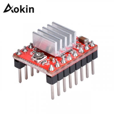
The cooling fins that I replaced were this type:
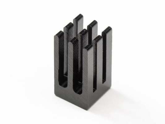
They were replaced with this model:
They have a slightly smaller footprint, thus they pose lower risk of shorting out any pins and they are about twice as tall, providing a lot more surface area and space for air to be blown through.
The new heatsinks are attached with 3M 8810 tape which also has better heat-transfer capability compared to the brandless tape that usually comes with the plain heatsinks.
Edited 1 time(s). Last edit at 04/26/2019 06:05PM by Ohmarinus.
http://www.marinusdebeer.nl/
|
Re: Soldering resistor onto A4988's ROSC pin July 20, 2019 06:07AM |
Registered: 6 years ago Posts: 5 |
Hi ,
I have been having the moire effect and have been trying to ground the R4 resistor by dropping a blob of solder on to it, for some reason my drive stops working after that, I have attached an image of my board with the 3d printed part with the moire effect. I am not sure as to which part needs to be soldered, or If I am actually soldering the correct resistor, or damaging the board while soldering.
any help would be much appreciated.
Thanks
Hussain
|
Re: Soldering resistor onto A4988's ROSC pin July 20, 2019 06:15AM |
Admin Registered: 11 years ago Posts: 3,096 |
What I do is just solder the resistor short. You are connecting the correct resistor but it's safer to just short the small gap between the SMD resistor's pins. The image is not really clear, but in the first image it looks as if you might have touched the processor on the stepper driver with the heating iron? Make sure you don't get solder on any of the other parts.
http://www.marinusdebeer.nl/
http://www.marinusdebeer.nl/
Sorry, only registered users may post in this forum.


