Auto bed level techniques and questions
Posted by VTE
|
Auto bed level techniques and questions May 17, 2015 06:37AM |
Registered: 8 years ago Posts: 37 |
Hi,
I am using Marlin on an Arduino Mega 2560. Ramps 1.4 board.
My question is regarding the probe and nozzle offsets.
I carefully found my offsets and input them into my configuration.h file.
When facing my machine, my probe is to the right and behind the nozzle. I am currently experimenting with different configurations. See below.
My issue is the consistent first layer gap. When I finally find my first layer gap by attempting to print for the first time with a new auto level bracket (all the measurements for the first layer gap are approximations at that point) I upload the firmware with that value.
After two or three prints, that first layer gap will not be the same. I thought that maybe the micro limit switch I was using was causing this. Maybe there is a range of engagement for the switch and it is not very repeatable. I do not know.
So I ruled out other things, I got 1/4" thick borosilicate because I thought my 1/8" glass wasnt flat and that caused unevenness in my first layer print, turns out that was NOT the cause. Moving on...
I stiffened up my servo bracket and servo horn where the limit switch probe is mounted. That helped, but only a little. The machine still sometimes prints off the plane of the bed (in the air print, auto level over corrects) even though the offsets are set up correctly in the firmware and my glass is perfectly flat, the mounting hardware is very stiff too so no flexing there.
I am still using the same limit switch for all these changes, at this point the limit switch is the very last thing I can modify for better repeatability. I am not sure what else this could be.
Can someone tell me if I have to put in something other then my offsets for the dot product calculations to be done correctly? Please see config.h lines below.
#define ENABLE_AUTO_BED_LEVELING // Delete the comment to enable (remove // at the start of the line)
#define Z_PROBE_REPEATABILITY_TEST // If not commented out, Z-Probe Repeatability test will be included if Auto Bed Leveling is Enabled.
#ifdef ENABLE_AUTO_BED_LEVELING
//
//
//
//
#define AUTO_BED_LEVELING_GRID
#ifdef AUTO_BED_LEVELING_GRID
#define LEFT_PROBE_BED_POSITION 55
#define RIGHT_PROBE_BED_POSITION 150
#define FRONT_PROBE_BED_POSITION 90
#define BACK_PROBE_BED_POSITION 200
#define MIN_PROBE_EDGE 10 // The probe square sides can be no smaller than this
// Set the number of grid points per dimension
// You probably don't need more than 3 (squared=9)
#define AUTO_BED_LEVELING_GRID_POINTS 2
#else // !AUTO_BED_LEVELING_GRID
// Arbitrary points to probe. A simple cross-product
// is used to estimate the plane of the bed.
#define ABL_PROBE_PT_1_X 15
#define ABL_PROBE_PT_1_Y 180
#define ABL_PROBE_PT_2_X 15
#define ABL_PROBE_PT_2_Y 20
#define ABL_PROBE_PT_3_X 170
#define ABL_PROBE_PT_3_Y 20
#endif // AUTO_BED_LEVELING_GRID
// Offsets to the probe relative to the extruder tip (Hotend - Probe)
// X and Y offsets must be integers
#define X_PROBE_OFFSET_FROM_EXTRUDER 22 // Probe on: -left +right
#define Y_PROBE_OFFSET_FROM_EXTRUDER 82 // Probe on: -front +behind
#define Z_PROBE_OFFSET_FROM_EXTRUDER -8.98 // -below (always!)
#define Z_RAISE_BEFORE_HOMING 10 // (in mm) Raise Z before homing (G28) for Probe Clearance.
// Be sure you have this distance over your Z_MAX_POS in case
#define XY_TRAVEL_SPEED 8000 // X and Y axis travel speed between probes, in mm/min
#define Z_RAISE_BEFORE_PROBING 15 //How much the extruder will be raised before traveling to the first probing point.
#define Z_RAISE_BETWEEN_PROBINGS 5 //How much the extruder will be raised when traveling from between next probing points
#define Z_RAISE_AFTER_PROBING 15 //How much the extruder will be raised after the last probing point.
If anyone has any other suggestions for a more repeatable limit switch, let me know. I would appreciate it.
|
Re: Auto bed level techniques and questions May 17, 2015 01:28PM |
Registered: 9 years ago Posts: 182 |
|
Re: Auto bed level techniques and questions May 18, 2015 01:21AM |
Registered: 9 years ago Posts: 288 |
|
Re: Auto bed level techniques and questions May 18, 2015 02:02AM |
Registered: 8 years ago Posts: 37 |
Mount is sturdy.
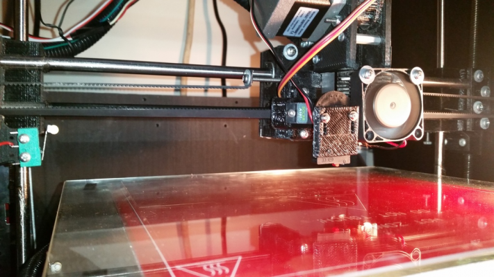
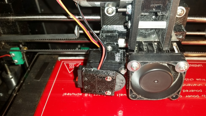
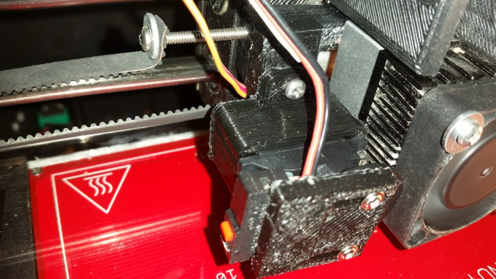
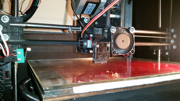
Here are some pictures of my current setup. Note that in my first post i mentioned that my probe was behind and to the right of the nozzle. In these pictures it is in front and to the right, I have since changed the position to bring the switch as close as possible to the nozzle to reduce error. This setup is very stiff.
Not sure what else I can do to increase repeatability and make the system more robust, it just isnt as much as I would like. I guess the caveat that I didnt mention is, I own a 3D printing business and I print 100s of parts a week so the machines are on practically all the time. The repeatability really is important.
Sorry, only registered users may post in this forum.


