Induction Heated Nozzle
Posted by aka47
|
Re: Induction Heated Nozzle October 15, 2010 04:08PM |
Registered: 14 years ago Posts: 380 |
|
Re: Induction Heated Nozzle October 15, 2010 05:12PM |
Registered: 14 years ago Posts: 387 |
I like to keep myself as far away from lead as possible...
Aluminum would be quite interesting though.
Here's another neat thing: The induction heater can probably be designed as a kind of induction motor, too, so that the force it exerts on the melting metal wire will propel it out of the nozzle. That might help defeat the problem of surface tension that plagues metal extrusion.
|
Re: Induction Heated Nozzle October 16, 2010 09:43AM |
Registered: 16 years ago Posts: 900 |
Guys
I have been musing on this a little and agree that perhaps the easiest way to the electronics is to re-purpose a dedicated switch mode voltage regualtor IC.
Current Mode Flyback voltage regulators commonly use current sensing as a way to sense how much regulation they need to apply and are completely insulated from the secondary.
(Flyback converters use a transformer with isolated primary and secondary windings.)
I can't help but feel that there may be some mileage in this route. Given that the Primary is our input coil , the secondary is the single turn nozzle (or metal tube inside a glass nozzle). For a given known power input the sensed current flow in the secondary will be a function of that of the material and its resistance at the temperature it is running at.
Simply short the widning of the secondary and leave out the diode producing a purely resistive load.short circuit
All very novel.
The IC's are relatively common place.
[www.national.com]
[en.wikipedia.org]
[www.national.com]
It would be interesting to see how much noise it generated at 500K, As the secondary is a closely coupled short circuit (even more so if made from ferrous matterial) the external magnetic field should be negligable. Switching should make more noise.
thoughts for what they are worth.
aka47
Necessity hopefully becomes the absentee parent of successfully invented children.
|
Re: Induction Heated Nozzle October 16, 2010 09:57AM |
Registered: 16 years ago Posts: 900 |
maybe something like (but certainly not limited to) a LT1076
[www.rapidonline.com]
Necessity hopefully becomes the absentee parent of successfully invented children.
[www.rapidonline.com]
Necessity hopefully becomes the absentee parent of successfully invented children.
|
Re: Induction Heated Nozzle October 16, 2010 11:38AM |
Registered: 16 years ago Posts: 900 |
A better example of the technology (again not limited to) is perhaps the LT3573
[www.linear.com]
This looks at the primary waveform to work out what the voltage is in the secondary. Maybe having a single shorting turn in the secondary will mess with this, maybr not.
I guess we are a little off the "conventional" map here.
Some experimentation is needed.
Essentialy the ouput turn (Nozzle or heater insert) is a constant load that varies only with the effect of its induced temperature.
Necessity hopefully becomes the absentee parent of successfully invented children.
|
Re: Induction Heated Nozzle October 16, 2010 12:43PM |
Admin Registered: 17 years ago Posts: 7,879 |
Trouble is you want the temperature control repeatable to a least 5C at 240C. That will give a very small change in load current. I doubt you would be able to resolve it the other side of the transformer, particularly as the transformer will get warm itself and its winding resistance will change.
[www.hydraraptor.blogspot.com]
[www.hydraraptor.blogspot.com]
|
Re: Induction Heated Nozzle October 16, 2010 03:54PM |
Registered: 14 years ago Posts: 387 |
|
Re: Induction Heated Nozzle October 16, 2010 04:53PM |
Registered: 16 years ago Posts: 900 |
I guess of course the current sensing method is only really necessary for those going with a glass nozzle design.
Otherwise:-
Where I could get a thermistor or some such in contact with the end/side of the nozzle I would go with that.
Assuming that there is noise to pickup. As the frequency is high, known and fixed it is doable to filter it out of the thermistor leads with something like a Pi filter. At the reading end given that the temperature time constant is fairly long (in comparison to microprocessor time) I would oversample and do a running average. Either or both depending on the results of experimentation.
To control the switching regulator it may be as easy as Nopheads sugestion of bang bang.
For smoother control with the switching perhaps doing something clever with the reference voltage will give variable power output. (r2r d to a off the back of a 74ls595 spi controlled shift register)
Something to come back to. At the moment I am determined not to get distracted from finally getting my Huxley into service.
Necessity hopefully becomes the absentee parent of successfully invented children.
|
Re: Induction Heated Nozzle October 22, 2010 03:26AM |
Registered: 14 years ago Posts: 387 |
|
Re: Induction Heated Nozzle October 22, 2010 04:20AM |
Registered: 16 years ago Posts: 900 |
|
Re: Induction Heated Nozzle October 22, 2010 12:29PM |
Registered: 14 years ago Posts: 387 |
Yes... a mild steel ring ought to change resistance by 0.13% per degree C, and have a higher resistivity in general. It also has the advantage of a not needing as high frequencies, due to its magnetic permeability. But I would be concerned about corrosion.
Over a 5 degree C range, that results in a restance change by 0.63%.
These calculations are assuming that the cylinder wall thickness is higher than the penetration depth of the magnetic field, which requires a high frequency. I'll try later on to make them general for a thin-walled cylinder too, or a low frequency.
The formula I've derived is
R = (L/pi*d)sqrt(p w u / 2) sqrt(1 + a(T-T0))
where
R = resitance of heater tube
L = length of heater tube
d = diameter of tube
p = resistivity of the metal at 20 C
w = frequency of the AC signal
u = magnetic permeability of the metal
a = temperature coefficient of the metal at 20 C
T = temperature of the metal
T0 = 20 C
Edited 3 time(s). Last edit at 10/22/2010 12:37PM by jbayless.
|
Re: Induction Heated Nozzle October 23, 2010 10:42AM |
Registered: 16 years ago Posts: 900 |
|
Re: Induction Heated Nozzle October 25, 2010 08:24PM |
Registered: 14 years ago Posts: 380 |
An 8 bit ADC with a pre-amplifier designed to amplify the signal at the top end to just under 5 volts has a resolution of 0.39% per LSB. That means that under ideal conditions, the full range of signal change would be 2 LSBs. With a 10 bit ADC, that would be 8 LSBs. The other option is to subtract a set level, such 100C or even 20C, and further amplify the signel.
The bigger problem I see is that we are still not sure what 'the signal' is. Feedback from the secondary back into the driven voltage of the primary might be hard to sense among the power and background noise of the power supplied to the primary. Perhaps the resistance of the secondary will affect the resistance of the primary enough to change the resonant frequency. The power could be shut off for a brief period and voltage controller oscillator used to sweep up and down around the resonant frequency and measure the change in resonant frequency with changing resistance of the secondary. But even then the temperature of the primary will affect that, too. And iron only has a slightly higher thermal coefficient of resistivity than the copper in the primary. I fear that reading the temperature by reading the resistivity of secondary is going to be tough. But if it works, it will be the most direct reading.
Mike
|
Re: Induction Heated Nozzle October 25, 2010 10:18PM |
Registered: 16 years ago Posts: 900 |
I will be honest I am starting to get towards the limits of my grip on the subject so could be a little out.
My understanding is that with Current mode Flyback converters you are not actually getting feedback from the secondary. You are measuring how much is left in the primary at a given point in time such that you can infer how the conditions in the secondary are impeding energy transfer from primary to secondary. ie feedback by virtue of not being able to feed energy forward.
I was instructed some time ago to think of flyback design like passing bucket of energy down a line by pouring it from bucket to bucket. (It is a long time since I did any flyback design, even then it was a touch iterative)
If the passing of energy from the primary bucket is impeded by the fact that there isn't enough room in the secondary bucket to take it all. The primary will have more left in it if you sample it at the same point in the transfer cycle.
When doing current mode you are really looking at how much current rather than how much voltage.
So for a given fixed PWM mark/space (at a known frequency and voltage) will transfer at most a fixed amount of energy into the primary bucket. If the primary to secondary bucket pouring is complete when we next look in the primary bucket it will be empty. If there is a delay (it is taking longer to empty the secondary bucket) when we look there will be something left in the primary bucket. the amount is proportional to how much the secondary bucket is impeded from dumping its contents into the bucket of the load.
Where we are passing more energy into the bucket chain than is being taken out there will be a measurable residue such that we reduce how much we put in. Where it is all gone we can increase the flow until there is a measurable residue. As we know exactly the rate at which we are putting energy in we also know how much (if we take into account losses) is being taken out.
In effect we are measuring the rate of flow of energy. Rate of flow in electronics is current. (voltage is directly analogous to pressure)
In our case the secondary and the load are exactly the same thing. Our secondary bucket has a hole in it which is where the energy is dumped as heat into the plastic. The size of the hole in the bucket is affected by the temperature of the secondary. Which is of course affected by the temperature of the plastic.
There is another way of doing this with flyback converters and this is to put a third (or sensing ) winding on the transformer and use this to measure energy surplus.
All in all though looking at the figures we have been talking about there is very real doubt as to whether we are going to be able to resolve this adequately with A to D techniques.
Do we actually need to resolve it ??
Would it actually be enough to leave this to the analogue control circuitry in the switch-mode controller chip (it is what it was designed for and is good at it) ??
Instead we could take the view that the switch mode circuit will keep it a certain set point and we only really need to command the set point. (a bit like driving stepper motors)
At the minimum we could operate on this optimistic basis, or better still look for some form of signal (no error voltage perhaps) that says the temp is as commanded. Any error voltage greater than a certain figure says we are still getting to the temperature we commanded.
I can't see any easy way to do this other than hooking some stuff up and experimenting. We may yet be barking up the wrong tree.
Cheers
aka47
Necessity hopefully becomes the absentee parent of successfully invented children.
|
Re: Induction Heated Nozzle October 25, 2010 10:32PM |
Registered: 14 years ago Posts: 387 |
I think we would not be able to sense it directly with an A to D. First we'd probably want to use a balanced wheatstone bridge, and then an instrumentation amplifier+high pass filter to boost the signal.
I'm not sure about using a third winding, because that winding would also have a resistance change with temperature, and unlike the primary coil where we can use DC current to compensate, there might not be a way to do so with a third coil.
As for using the switch-mode circuitry - perhaps, although I don't know enough about switching-mode controllers to say if they could be programmed to do that job for us.
|
Re: Induction Heated Nozzle October 26, 2010 06:19PM |
Registered: 14 years ago Posts: 380 |
aka47,
if I understand correctly, you are recommending that we use a standard switch mode power supply controller, and externally measure the temperature and find what reference voltage/current needed to power that much energy into the windings. It would not have temperature feedback, but would be stable amount of power being added. This may be good enough, although we might need to change the set point of the switching power supply controller depending on how fast filament is being pushed in. That would be more of a dead reckoning system, but probably good enough.
Mike
|
Re: Induction Heated Nozzle October 26, 2010 07:35PM |
Registered: 16 years ago Posts: 900 |
To be honest what I am suggesting depends a little on what you want to do with it. I am talking about two different scenarios at the same time and this will probably be confusing. Sorry.
In both cases I am suggesting using a fly-back SMPSU circuit and controller (to be decided, choose one you fancy) as the way to run the induction heater. With the micro-controller telling it what temperature to maintain and the SMPSU chip getting it there and keeping it there. In short re-purposing an off the shelf flyback IC as an Induction heating controller.
SMPSU control is not trivial to design but is easier a lot easier if you are using an ASIC (application specific integrated circuit) or an off the shelf controller chip. Once designed though it is relatively easy to replicate and build. Arriving at a design that works is the hard bit.
For folk planning on using glass nozzles with an internal short tube of metal as a heater then as you suggest I am looking at the feasibility of detecting what is going off inside that tube by looking at how much power we think should be flowing in versus how much actually is flowing in. (ie non contact heating through induction and, probably overly ambitious, non contact deduction of temperature through current/energy flow sensed at the primary).
For folk like myself who are looking at a metal nozzle then I will be using a thermistor or some such in contact with the nozzle as the feedback to a standard fly-back circuit with the aim of regulating the temperature in a direct contact sort of way. (Look at an example of a standard fly-back circuit that uses an opto coupler or direct voltage sensing to regulate the output. Now swap the opto/direct voltage feedback for one that is temperature Dependant ie the feedback is a voltage from a thermistor and you have a very precise closed loop induction heater setup)
In both cases (and it may not be possible in one, other or both) once you can achieve stable closed loop control of a given temperature, then you can control the temperature by changing the voltage that the circuit is regulating for.
Don't know if this is any help or if I have muddied the waters a little bit more.
Cheers
aka47
Necessity hopefully becomes the absentee parent of successfully invented children.
|
Re: Induction Heated Nozzle December 22, 2010 02:03PM |
Registered: 14 years ago Posts: 387 |
Hi everyone,
Just reviving a dead thread here.
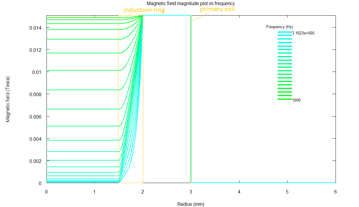
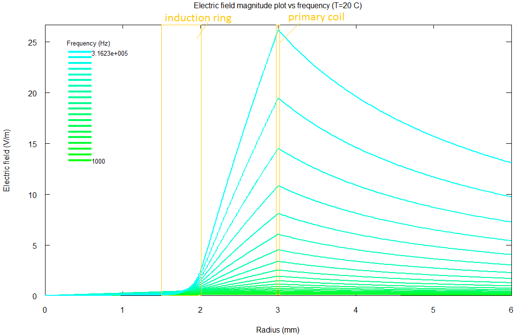
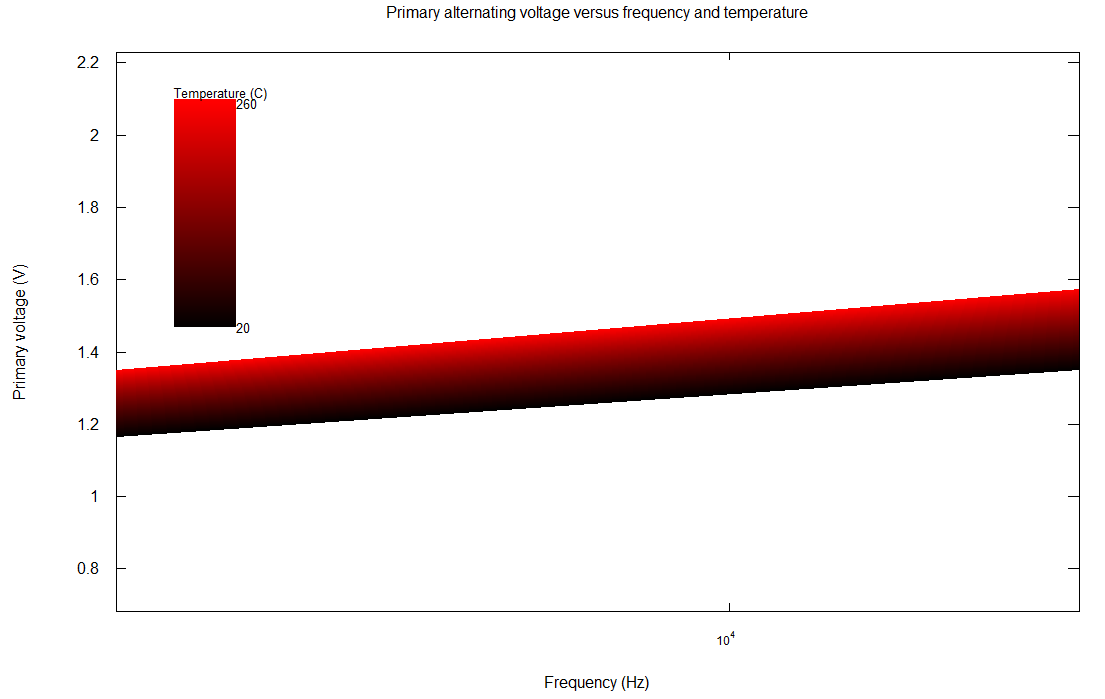
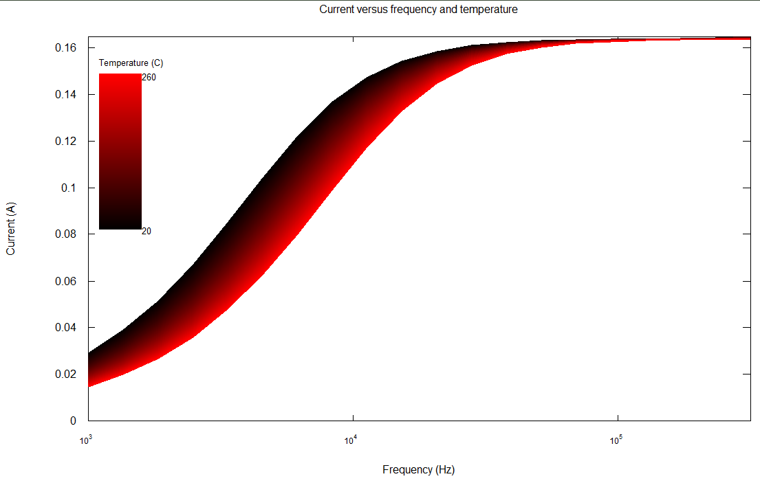
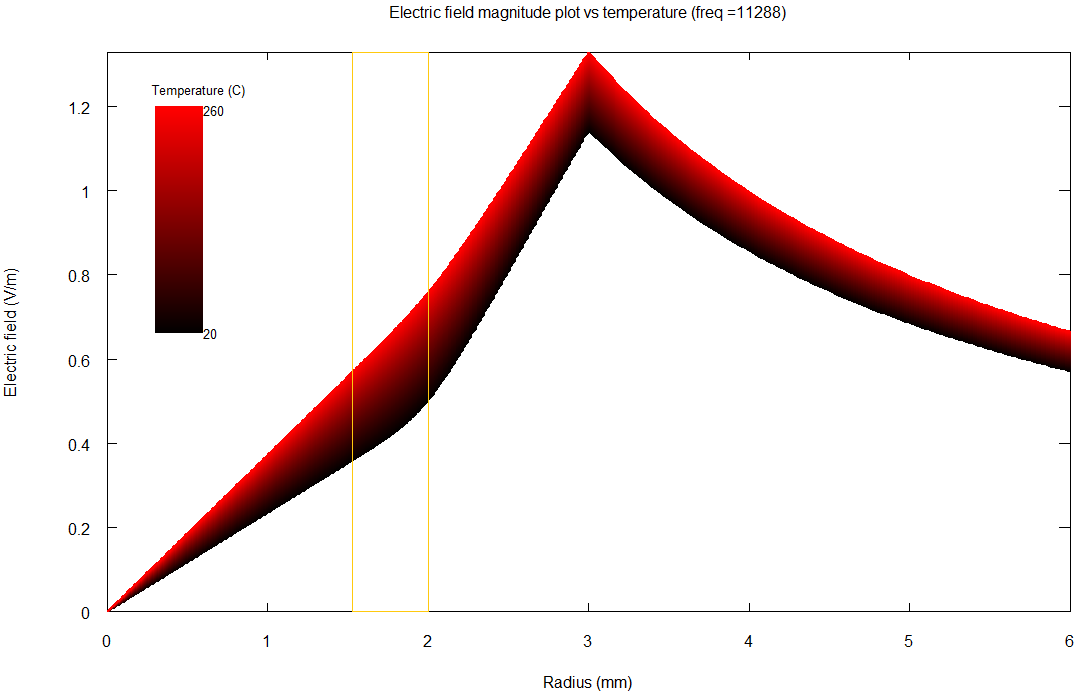
I've done a significant amount of modelling work on the induction heated nozzle (more still to come). Here's some graphs that I've generated to help with the design. To generate them, I solved Maxwell's equations on a cylindrical domain, assuming the induction ring and primary coil are of infinite length -- an approximation that can later be checked with finite element modelling. The graphs are generated by an Octave script I wrote to model the scenario.
In these cases, I've put 2 amps in the primary coil, with N=60 windings. The induction ring is made of copper, with an inner diameter of 3mm and an outer diameter of 4mm. Then there's a 1 mm glass wall, so the primary coil is wound at 6 mm diameter. All these numbers can be easily changed.
Unfortunately, due to numerical instability, I can't solve for higher frequencies than about 300 kHz.
I'm going to do more detailed modelling to determine how sensitive the primary voltage is to the temperature of the induction ring, and to see how things like the ring thickness and material affect the performance. Pretty soon I ought to be ready to start developing a temperature controller circuit.
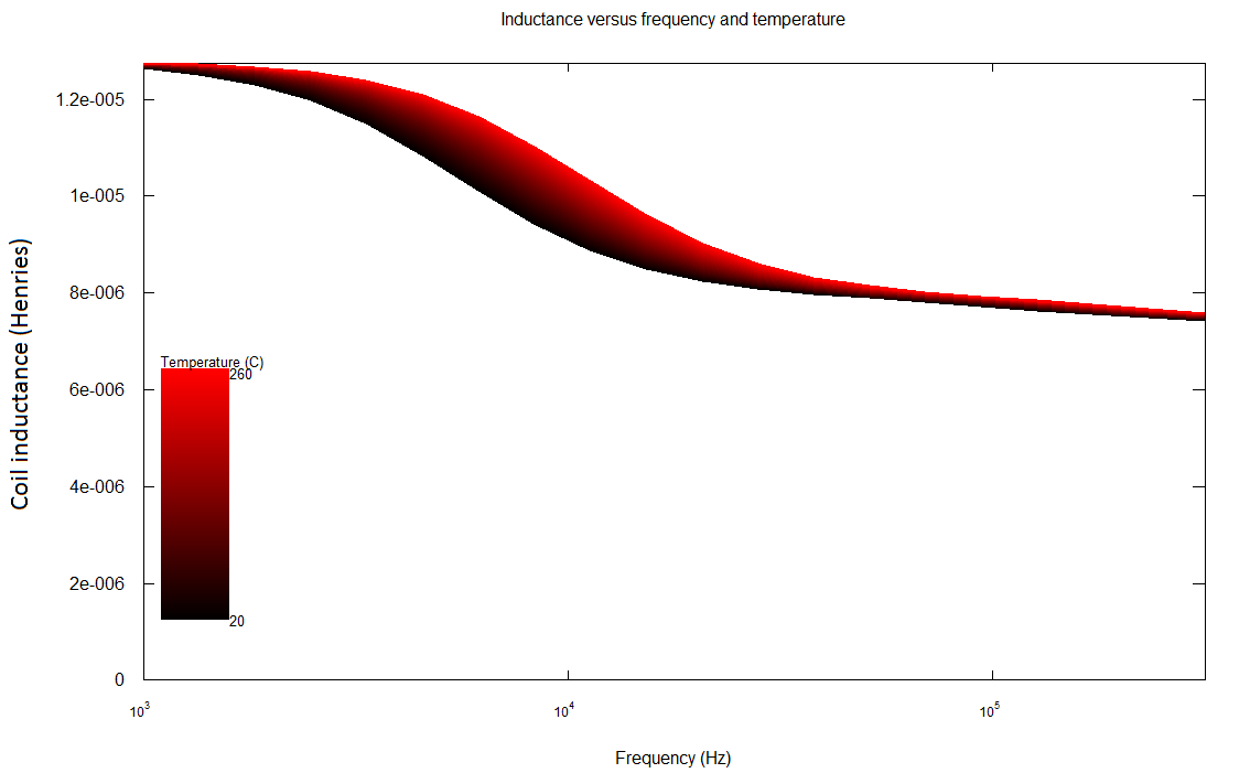
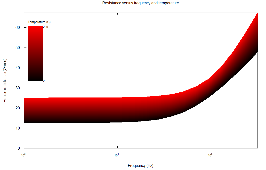
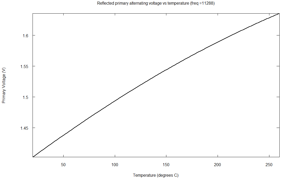
From a temperature sensitivity perspective, it looks like the ideal frequency is around 12 kHz, which should make for not-too-expensive electronics. The sensitivity here is about 0.06% per degree C. Or, more concretely, 0.6 mV/V per degree C. That is, to keep within +- 2 degrees C would require electronics that can detect a voltage change of 2.4 mV / V, which I think is not too difficult.
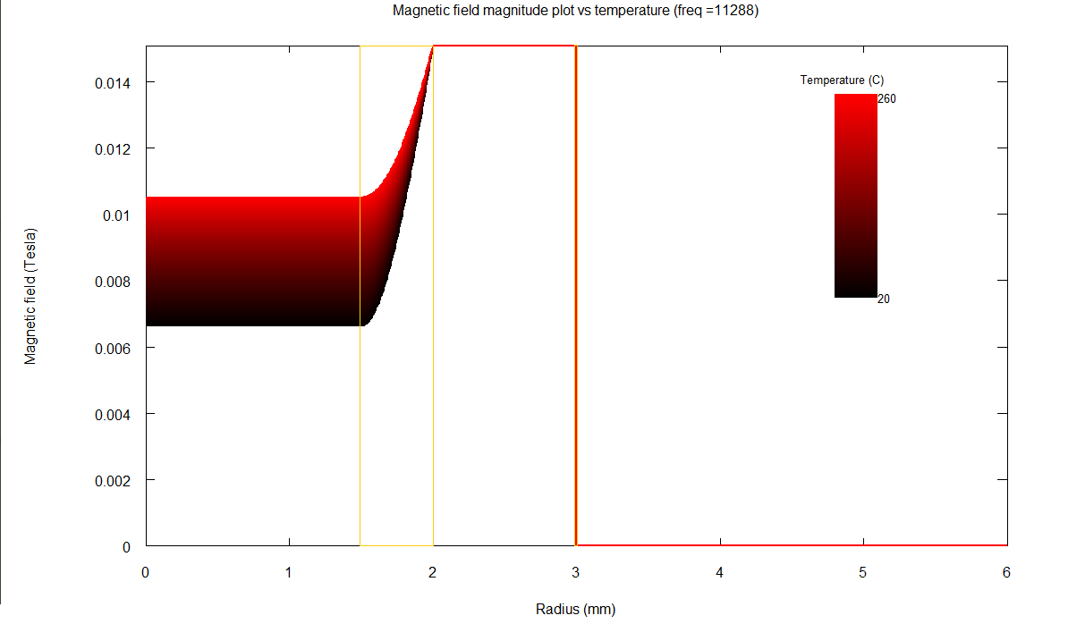
Most of these are plots versus frequency. To illustrate the temperature dependence, I picked the max sensitivity frequency and plotted some of its graphs versus temperature.
Edited 6 time(s). Last edit at 12/22/2010 04:59PM by jbayless.
Just reviving a dead thread here.
I've done a significant amount of modelling work on the induction heated nozzle (more still to come). Here's some graphs that I've generated to help with the design. To generate them, I solved Maxwell's equations on a cylindrical domain, assuming the induction ring and primary coil are of infinite length -- an approximation that can later be checked with finite element modelling. The graphs are generated by an Octave script I wrote to model the scenario.
In these cases, I've put 2 amps in the primary coil, with N=60 windings. The induction ring is made of copper, with an inner diameter of 3mm and an outer diameter of 4mm. Then there's a 1 mm glass wall, so the primary coil is wound at 6 mm diameter. All these numbers can be easily changed.
Unfortunately, due to numerical instability, I can't solve for higher frequencies than about 300 kHz.
I'm going to do more detailed modelling to determine how sensitive the primary voltage is to the temperature of the induction ring, and to see how things like the ring thickness and material affect the performance. Pretty soon I ought to be ready to start developing a temperature controller circuit.

From a temperature sensitivity perspective, it looks like the ideal frequency is around 12 kHz, which should make for not-too-expensive electronics. The sensitivity here is about 0.06% per degree C. Or, more concretely, 0.6 mV/V per degree C. That is, to keep within +- 2 degrees C would require electronics that can detect a voltage change of 2.4 mV / V, which I think is not too difficult.
Most of these are plots versus frequency. To illustrate the temperature dependence, I picked the max sensitivity frequency and plotted some of its graphs versus temperature.
Edited 6 time(s). Last edit at 12/22/2010 04:59PM by jbayless.
Attachments:
open | download - Bfield_Annotated.png (39.4 KB)
open | download - Efield_Annotated.png (38.8 KB)
open | download - Inductance.png (42.3 KB)
open | download - Resistance.png (53.7 KB)
open | download - VAC_Zoom.png (34.3 KB)
open | download - Current.png (59.6 KB)
open | download - VoltageVsT_11288hz.png (23.1 KB)
open | download - Bfield_vs_T_11288hz.png (43.8 KB)
open | download - Efield_vs_T_11288hz.png (98.9 KB)
|
Re: Induction Heated Nozzle December 23, 2010 10:09AM |
Registered: 16 years ago Posts: 900 |
Like wow, gobsmacked.
That is a solid lump of work there. I am truly impressed. You must be getting on for a couple of papers worth of work there if not a thesis.
What frequency to model for is an interesting question. My gut feel for this is that 100Khz is plenty.
For example the LT3573 can be set to switch at between 40 and 1000 Khz.
40Khz is a sensible minimum as it is safely beyond hearing range.
For practical purposes when doing an actual implementation (as opposed to modeling) there are perhaps good reasons to avoid an exact 100Khz (it has harmonics that are nicely placed to disrupt anything RF sensitive). Perhaps choosing something that has multiples that are less likely to fall on the sorts of spot frequencies that will disrupt radio comms. Unless you can guarantee shielding and or zero emissions.
For modeling though any frequency you can manage is good.
Whilst you get savings on component size at higher frequencies you get increasing switching losses. The switching times (or edges if you like) are constant for any given device what ever speed you switch at. At too high a frequency you are spending more time proportionately switching than powering. (Gross over simplification but explains the principle)
A bunch of this is typically a feature of gate capacitance on fet based designs.
So personally speaking 300Khz should be plenty for practical and perhaps concept proving purposes.
Cheers
aka47
Necessity hopefully becomes the absentee parent of successfully invented children.
|
Re: Induction Heated Nozzle December 23, 2010 01:26PM |
Registered: 14 years ago Posts: 387 |
Thank you! =)
Yeah, I hadn't thought about radio-frequency harmonics... at the least we'll have to filter the power so that harmonics are at a minimum.
On another note, right now I'm actually thinking that the best approach would be driving the coil with three different frequencies. The first will be a small DC component, used to measure the resistance of the copper windings and compensate for temperature shifts there. The second will be an 11.5 kHz signal used to measure the temperature of the induction ring inside the nozzle. And the third will be something higher - at least 100 kHz - which will heat the nozzle most efficiently. But something which won't disrupt radio devices, and which is within an efficient switching range for the electronics.
The three frequencies will be far apart enough from each other that they can be completely seperated from each other by bandpass filters, allowing the temperature measurements to be made...
This way, the power on the 11.5 kHz line can be quite small, allowing it to measure the temperature even when the extruder is supposed to be cooling down. The >100 kHz line will have its power controlled by the temperature measurements.
Edited 1 time(s). Last edit at 12/23/2010 04:39PM by jbayless.
|
Re: Induction Heated Nozzle December 23, 2010 06:39PM |
Registered: 16 years ago Posts: 900 |
I guess that is one route.
Personally I prefer a closer shave with Occams Razor (Raisor ??).
If I needed to know the temp of the primary circuit so as to null it out I would measure it with a thermistor. With suitable filtering. The time constant of thermistors is of the order of magnitude of seconds. So filtering this should be straight forward. Maybe a Pi filter.
There again if I wanted too close a shave I guess we wouldn't be having the conversation
If you can measure the temp of the primary then a quantity of measure and see may be enough to give you a lookup table to infer the rest from a combination of the LUT and the power calcs as discussed earlier.
Still rather complex though.
I guess this is why I am sticking with the idea of an exposed heated barrel that I can stick a temp sensor to for now.
The 11.5Khz signal though is an interesting idea.
aka47
PS if running the thing with two differing frequencies simultaneously watch out for the sum and difference products. (ie beat frequencies) when filtering. They should be far away enough though from 11.5Khz to make it feasible.
Necessity hopefully becomes the absentee parent of successfully invented children.
|
Re: Induction Heated Nozzle December 23, 2010 08:44PM |
Registered: 14 years ago Posts: 380 |
As far as RF interference goes, a little bit of googling and Wikipedia point out that for frequencies lower than 100Khz, shielding is best done with high permeability magnetic metal rather than just a Faraday cage. I found a listing on Electronic Goldmine for a sheet of 'ultraperm' that would not only block outgoing interference, but if wrapped around the induction heater, might improve the magnetic coupling. On the other hand, it might damp most of the transformer energy, I am not sure. On the other hand, just a short piece simple steel or iron tubing around the induction heater should keep the field lines inside the heater and the RF noise down. Not that stainless steel won't work here.
@jaybayless
Are you getting close enough that you want a couple of nozzles with copper tubing in the end to experiment with once you get the electronics worked out? I am just about to get deep into the FIRST robotics Mentoring season, but I may be able to whip out a couple test pieces. It is cheaper for me to buy 1/8th inch (3.175 mm OD) than true 4mm, but if the design works out well I can probably get some 4mm tubing from RS. In either case, I don't think I can get copper tubing that small locally, so there will also be a shipping delay. Let me know when you want something to test. Also, I will need to know how long the copper tubing should be, or it this truly a ring 16 gauge wire?
Mike
|
Re: Induction Heated Nozzle December 24, 2010 03:47AM |
Registered: 14 years ago Posts: 387 |
@aka47
My own opinion is that using no thermistor is simpler than using a thermistor, even if it makes the temperature sensing circuitry a bit more complex. From a point of view of constructing the extruder, a thermistor means an extra set of wires that can come loose, kapton-taping a little bead that can unseat itself...
Anyway, they're both good methods. Thermistors are definitely better-tested. My hope is that, once I've designed the induction heater properly, it will be the simplest and most failure-proof, even if the design is difficult at first.
I'm not too worried about beats. The three frequencies are 0 Hz, 11.5 kHz, and 100+ kHz, so they're spaced quite far apart.
@Mike
I'd be a bit worried about hysteresis losses, but that's still an interesting thought. The plot of the magnetic field I posted earlier shows that there is zero field outside the primary coil, but that's because it's assumed infinitely long - in practice, fringing effects will produce a non-negligible field there that ultraperm might help with. I don't know if anything will be able to shield the electric field though.
For prototypes I'm probably just going to make my own copper rings on the lathe, and trim them down until they fit in the glass tubes I already have (which are 3mm ID... I might need to get 4mm ID ones at some point). Actually, I wonder about this construction for an extruder: glass tube, ~6mm OD, 4mm ID. Copper ring, 4mm OD, 3mm ID. Teflon tube, 4mm OD, 3mm ID. (Or equivalent nearest inch sizes).
If you do make some for yourself, they'd need to be 1/8" ID, not OD, unless they're for that new, very fine filament. A thin wall thickness is a benefit though.
Also, earlier you mentioned possibly using quartz glass. It doesn't melt until upwards of 1650 C! That's higher than the melting point of stainless steel!
|
Re: Induction Heated Nozzle December 24, 2010 01:28PM |
Registered: 16 years ago Posts: 900 |
I would be cautious of putting a conductive tube around the primary. It would look like an aditional shorting turn to the magetic fields.
If you want to shield, a ferrite shield that is not electricaly conductive is much better.
A steel tub would be a bad idea.
This why transformers are made up from laminated steel or ferrite so as to avoid eddy currents and the associated losses and heating.
shielding and field concentration may be a good idea.
aka4au
Necessity hopefully becomes the absentee parent of successfully invented children.
|
Re: Induction Heated Nozzle December 24, 2010 02:01PM |
Registered: 14 years ago Posts: 387 |
|
Re: Induction Heated Nozzle December 24, 2010 06:04PM |
Registered: 16 years ago Posts: 900 |
I think we are both right.
The big question is how do we create something like ferrite.
I am the sad guy dragging a magnet down the beach on the end of a piece of string trawling for magnetite and rust.
The aim being to mix enough magneticaly conductive stuff. With non electricaly conductive binder (epoxy, ceramic, grp resin take your pick) to make castable magnetic components that don't conduct electricity.
There may be another way though. apparently some red pigments are in fact iron oxide. That renowned poor conductor of electricity that is magnetic..........
Necessity hopefully becomes the absentee parent of successfully invented children.
|
Re: Induction Heated Nozzle December 25, 2010 04:10AM |
Registered: 14 years ago Posts: 387 |
|
Re: Induction Heated Nozzle January 02, 2011 04:00AM |
Registered: 14 years ago Posts: 387 |
Moving on to the sensing circuit, I've run the simulation with a Maxwell bridge circuit for improving the temperature sensing sensitivity. (I have also written code to evaluate the Owen Bridge, analysis is forthcoming).
The best sensitivity I can get from a Maxwell bridge is -0.25 mV/(V degreeC), which is quite high. As well, because the bridge removes the DC offset, this can be amplified by an instrumentation amplifier.
The attached graph shows the voltage across the bridge for a +/- 2.5 volt AC source. Using the notation in
this webpage,
R1 = 11.4 Ohms
R2 = 49 Ohms
C2 = 1 uF
R3 = 0.807 Ohms
R4 = AC coil resistance. At 140 C = 0.189 Ohms, but varies with temperature
L4 = AC coil inductance. At 140 C = 9.24 uH, but varies with temperature
There's one free parameter (C2); when it's made lower, R1 and R2 increase. 1uF is an arbitrary value. R2 and R1 are chosen so that the bridge voltage is zero at a reference temperature of 140 C, and R3 is chosen by a numerical optimization for maximum sensitivity. This circuit is not power-efficient because R3 is higher than R4, which is another good reason not to use it for heating. In this case, the sensing bridge circuit would drain about 1 watt of power, of which about 0.2 watts would directly heat the extruder.
The sensitivity of the circuit in this example is -0.623 mV/degree C, before any active amplification. An instrumentation amplifier with a gain of ~30 would boost the sensitivity to 19 mV/degree C, which means that even a single degree C ought to be easily detectable by (for example) an arduino.
Edited 4 time(s). Last edit at 01/02/2011 04:09AM by jbayless.

Sorry, only registered users may post in this forum.