Is there any best practices for smooth rod diameter per hanging length?
Posted by realthor
|
Is there any best practices for smooth rod diameter per hanging length? November 24, 2015 11:03AM |
Registered: 9 years ago Posts: 1,035 |
Hi guys, I have a quick question. I am building a corexy and the length of the smooth rods that is not supported is 310mm (X) and 330mm(Y). Like usual, on X there are two such rods and on Y is one on each side.
I am planning the X carriage to support 2 hotends but it will be very light because I will be using bowden setup for the filament and perhaps even bowden-style tubing for cooling. The bowdens will be as short as possible to avoid the complications related to retractions/etc.
To keep the discussion short, what are OK diametres for these lengths of unsupported rods? I was going for 8mm for x and y and 10mm for Z. I believe 8mm for X still applies as there are two such rods but for Y I am having doubts (when the X carriage will be at the extreme side all the weight will mostly be on that smooth rod). Should I go for 10 on Y or maybe go for 10 for all axes?
Thanks for your input.
Edited 1 time(s). Last edit at 11/24/2015 11:05AM by realthor.
RepRap Lander concept on Concept Forge
RepRap Lander concept on RepRap Forums
My Things, mostly experimental stuff
|
Re: Is there any best practices for smooth rod diameter per hanging length? November 24, 2015 11:35AM |
Registered: 11 years ago Posts: 5,780 |
There should be a calculator on line that lets you calculate the sag in the rods due to gravity, and maybe even to estimate it with the weight of the extruder carriage as well. That said, larger diameter will always be stiffer for a given length so if the price difference isn't too large, I'd opt for the larger rails. I had 1/2" round rails on my machine and switched to linear guides for various reasons including their flexibility. I did not have any measurements of the actual flex- I just saw them flexing when I manually applied some force to them and didn't like it. If there's any way you can use fully supported rails or linear guides, I'd recommend doing that instead of using end-supported rails.
Keep in mind that with two rails you have to have some means of ensuring that they are parallel, and in the case of your X axis, they also have to be in the XZ plane. That sort of alignment can be tricky, and the longer they get, the harder it becomes. A single linear guide is like having two rails that are very accurately and permanently aligned. There is no play in the bearing block at all so there's no concern about slop in the bearings hurting print quality. Though it isn't optimal, you can use linear guides in an end-supported configuration, but you may still have to be concerned about sag, depending on the size of the rail. A single linear guide will usually be lower mass than two round rails and the associated hardware so they can help minimize moving mass which helps print speed and quality.
Edited 1 time(s). Last edit at 11/24/2015 11:44AM by the_digital_dentist.
Ultra MegaMax Dominator 3D printer: [drmrehorst.blogspot.com]
|
Re: Is there any best practices for smooth rod diameter per hanging length? November 24, 2015 02:02PM |
Registered: 9 years ago Posts: 722 |
Hi guys,
Calculate here : [www.amesweb.info]
Keep in mind you want at last a flex 10 times under the precision you expect
Look at 8x350mm Prusa i3's to make up your mind
++JM
Edited 1 time(s). Last edit at 11/24/2015 02:05PM by J-Max.
Calculate here : [www.amesweb.info]
Keep in mind you want at last a flex 10 times under the precision you expect
Look at 8x350mm Prusa i3's to make up your mind
++JM
Edited 1 time(s). Last edit at 11/24/2015 02:05PM by J-Max.
|
Re: Is there any best practices for smooth rod diameter per hanging length? November 24, 2015 02:59PM |
Registered: 9 years ago Posts: 1,035 |
Quote
J-Max
Hi guys,
Calculate here : [www.amesweb.info]
Keep in mind you want at last a flex 10 times under the precision you expect
Look at 8x350mm Prusa i3's to make up your mind
++JM
- Which value of those in the calculator is the flex? I assume only the "L" and "d" are changing, the density should be very similar between the carbon steel of the smooth rods;
- Do you have a particular build in mind? I can't find anything specific about a "8x350mm Prusa i3" other than different builds and smooth rods bundles that use 8mmx350mm steel rods. I found this Prusa i3 ERMES Edition that uses 8x320+8x350+9x370 smooth rods.
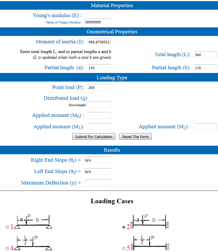
I found this calculator: http://www.aps.anl.gov/APS_Engineering_Support_Division/Mechanical_Operations_and_Maintenance/Calculators/ElasticBeam2.html but I am still trying to figure out how should I fill the inputs so I can see in the results the Maximum Deflection. I believe case 5 applies for both ends supported beams. I can't find though what kind of beams they are talking about, if it is round or just a bi-dimmensional mathematical approach.
BTW, what would be the weight of a normal dual extruder bowden carriage? I put 300grams in but that is 2 hefty cellphones worth of weight, perhaps a motor will get it to that weight.
Thanks.
Edited 8 time(s). Last edit at 11/24/2015 05:50PM by realthor.
RepRap Lander concept on Concept Forge
RepRap Lander concept on RepRap Forums
My Things, mostly experimental stuff
|
Re: Is there any best practices for smooth rod diameter per hanging length? November 24, 2015 03:45PM |
Registered: 9 years ago Posts: 1,035 |
Digging through the web I ended up on this page: http://www.nookindustries.com/LinearLibraryItem/Deflection_Calculation, that explains quite clearly the deflection phenomena.
It's a pity the values are for inches and I can't approximate anything to 8mm or 10mm.
On the other hand I managed to go through the aps.anl.gov fields and it goes like this:
- Young's modulus (E): 30000000 for steel, it's the same whatever the hardness
- Moment of inertia (I): = pi*r^4/4 =201.06192983 for 8mm rod and =490.873852123 for 10mm rod
- Total Length (L): 340mm (my X rod length) OBS: I had to also input the "Partial length (a)" and "Partial length (b)" so for the deflection at the middle I put 170mm for each
- Point load (P): I assumed my X carriage will not be more than 200gram per rod so I put 200 in this field for a 400grams X carriage (the header of the page says that values must be consistent so I've chosen millimeters and grams)
- I choose case 2 because case 5 would give me no result, and with the same (a) and (b) the case 2 actually is the same with case 5.
I then hit the submit for calculation button and it calculated the deflection at the mid point to -0.006787571487929661mm for 8mm rod and to -0.002780189281461786mm for 10mm rod. I don't know what the minus is in front of the numbers I hope I didn't make some terrible mistake.
The actual value will be even smaller due to the fact that the rod in reality is constrained/clamped at both ends leaving only 310mm that is not supported and the carriage is not a Point Load but a distributed load across the carriage's width.
Let's see what precision is appropriate for the above values (according to the 10 times rule)
1) 8x340mm rod: =0.006787571487929661*10= 0.06787571487mm
2) 10x340mm rod: =0.002780189281461786*10= 0.02780189281mm
Further on I went to see what weight for the X carriage would break the "10 times less" rule for the 8mm rod and it is 320grams per rod so a carriage of 640 grams will bend the rod more than the suggested value of 10 times less than the expected precision/resolution:
Point Load (P): =320 (grams) => Maximum Deflection (y)= -0.010860114380687458 (*10=0.1086011438), assuming that we're going for a 0.1mm resolution on X & Y axes.
For the two Y axes I'll have to add up the weights of the X carriage and the two Y carriages plus the weights of the two X rods and see if I am still under the radar. If not, 10mm for the Y axis.
Edited 3 time(s). Last edit at 11/24/2015 06:17PM by realthor.
RepRap Lander concept on Concept Forge
RepRap Lander concept on RepRap Forums
My Things, mostly experimental stuff
|
Re: Is there any best practices for smooth rod diameter per hanging length? November 24, 2015 06:49PM |
Registered: 9 years ago Posts: 1,035 |
Y axis Mximum Deflection for 8x360mm maxes out at 270grams per rod load. Let's make an exercise of approximation:
We should calculate the load on each Y rod at the middle with the X carriage to the outmost position that is closest to that rod. I don't know the exact number for how much of the total X carriage+X rods weight will be concentrated on the Y rod but I'll assume that it will take the whole X carriage's weight plus half of the weight of each rods, so 1 rod's worth of weight.
Let's see each part's weights:
2x8mmx340mm steel shaft weigh 268.299887grams according to http://www.bostoncenterless.com/resources-metal-weight-calculator.htm so Y rod will take 134grams when the carriage is closest to it.
4 LM8UU (X carriage) + 2 LM8UU (Y carriage riding on the Y rod) = 6x13grams= 78grams
Plastic parts (X carriage+Y carriages) -no idea- say 100grams (is this too much? too little?)
2xHotends + bowden + wires/heating cartriges ~50grams each = 100 grams
Inductive probe ~45 grams
bolts and what not for another 20 grams
Total estimate = 134+78+100+100+45+20= 477 grams (~500). This is way more than the weight for the "10 times less" rule for the maximum deflection. Even if the actual hanging length of the Y rod is less than 360mm - being constrained/clamped at the ends- and the force is not concentrated right in the middle but spread across the length of two linear bearings, it just doesn't look good.
For 10mm rod the Y axis Mximum Deflection is around 650grams per rod, which can take the guesstimated value of 432 grams.
I hope that these calculations are right and I didn't ruin this whole evening for nothing
-------------------------------------------------------------------------------------------------------------------
Now the funny part is that this is for static loads.
I am scared to think about dynamic loads but let's just put it into perspective:
- the X carriage accelerates towards the Y axis trying to fill an infill line.
- the software knows how to accelerate the nozzle and then decelerate towards the end of the said line.
But at high speeds the carriage is pulled towards each Y axis with a certain force. The weight of the carriage creates an inertia that acts the same with the static load on the vertical plane but this time it's on the horizontal plane. Each time the X carriage is accelerated towards a point, the Y rod that is pulling it tries to bed towards it due to the inertia.
At what speeds this inertia-caused load exceeds the corresponding static weight so the deflection on the rod in the horizontal plane goes to less than resolution/10?
I'll leave it as homework, it's 2AM here and I am dead beaten.
Edited 3 time(s). Last edit at 11/24/2015 07:27PM by realthor.
RepRap Lander concept on Concept Forge
RepRap Lander concept on RepRap Forums
My Things, mostly experimental stuff
|
Re: Is there any best practices for smooth rod diameter per hanging length? November 24, 2015 08:28PM |
Registered: 10 years ago Posts: 814 |
|
Re: Is there any best practices for smooth rod diameter per hanging length? November 24, 2015 09:05PM |
Registered: 9 years ago Posts: 1,035 |
I'd like to go off the beaten path with this one as much as possible. I need a printer to support my other experiments (Lander is taken apart on a shelf waiting for parts).
If smooth rod is the norm, I'll go with smooth rod. I just wanted to make sure there is a reason to use 10mm rods or 8mm supported rods. And for my dimensions it seems that for Y 8mm unsupported rod does not cut it.
The calculations above might be of help to others who want to know what rods to buy.
RepRap Lander concept on Concept Forge
RepRap Lander concept on RepRap Forums
My Things, mostly experimental stuff
|
Re: Is there any best practices for smooth rod diameter per hanging length? November 25, 2015 04:59PM |
Registered: 8 years ago Posts: 150 |
Missed the pulleys bearings and belts of the core-setup that will add some wight but I think the plastic is a bit too much so it will even out. The total error is the sum of the X and Y flex, I can't figured out if that is how this was calculated or not. And it - sign on the result indicate the direction of the flex, down.
Edited 1 time(s). Last edit at 11/25/2015 04:59PM by SlowFoot.
Edited 1 time(s). Last edit at 11/25/2015 04:59PM by SlowFoot.
|
Re: Is there any best practices for smooth rod diameter per hanging length? November 25, 2015 06:41PM |
Registered: 9 years ago Posts: 1,035 |
Quote
SlowFoot
Missed the pulleys bearings and belts of the core-setup that will add some wight but I think the plastic is a bit too much so it will even out. The total error is the sum of the X and Y flex, I can't figured out if that is how this was calculated or not. And it - sign on the result indicate the direction of the flex, down.
Yeah, maybe missed more but once I have a system I can re-calculate as I go.
If this is not how it was measured it is what I found online and it is plausible (I ended up on an engineering forum calculating Deflection for some CNC stuff and I got the Moment of Inertia formula from there so I could use the aps.anl.gov calculator).
Now at least reprappers can calculate these numbers for their situation and see if Deflection is one more thing that is affecting their prints.
As @madmike suggested, for large spans maybe tubes are better because they are less prone to deflection and lighter as well... too bad there is no way to get accurate linear tubes instead of rods.
Ideas:
- maybe print the XY bearings in tribo-filament (iglidur from igus) that would make them light
. But then again, for 3d printed bearings, i'd resort to a SLA printer of sorts not FDM. I Don't think the balls inside would be round enough or strong enough with fused layers.- For XY rods self-lubricating graphite bushings could be used or even 3d printed bushings if this Tribo filament would prove capable.
- The fans could be bowden-ized just as the filament (a short tube would be required though to prevent loss in pressure/etc and squirrelcage blowers should be used)
With a very light carriage we could use 2mm wall aluminum tubing or carbon rods instead of steel linear rods, but those should be reeealy linear too.
Edited 1 time(s). Last edit at 11/26/2015 05:54AM by realthor.
RepRap Lander concept on Concept Forge
RepRap Lander concept on RepRap Forums
My Things, mostly experimental stuff
|
Re: Is there any best practices for smooth rod diameter per hanging length? November 26, 2015 04:22PM |
Registered: 8 years ago Posts: 150 |
You done a good piece of work, keep it up.
What matters is how the distance between the nozzle and the bed change over the print area, that is why the X and Y flex should be added together, unless the firmware lets you compensate for flex on each axis.
With 10 mm rods you are talking about pretty small errors, there are other parts that, most likely, will have larger impact on the nozzle-bed distance. Setting up the X and Y-rods parallel to the bed, getting the z- movement equal, keeping the bed flat when heating it, flex in the frame and so on. In the end it will be very hard to take meaningful measures of anything but the total sum of all the errors and you can make a software compensation for that.
Sorry, only registered users may post in this forum.