This engineer claims 100 grams direct extruder. I want one
Posted by realthor
|
Re: This engineer claims 100 grams direct extruder. I want one June 17, 2016 01:39PM |
Registered: 8 years ago Posts: 62 |
Quote
Curry44
Adding the .stls files for the 1,75/3mm version would be useful.
STL-files for 3mm and 1.75mm added
|
Re: This engineer claims 100 grams direct extruder. I want one June 17, 2016 04:07PM |
Registered: 8 years ago Posts: 93 |
|
Re: This engineer claims 100 grams direct extruder. I want one June 20, 2016 03:29PM |
Registered: 8 years ago Posts: 62 |
Quote
asbo
Thanks
Could you also upload each printed component as a separate STEP file? I think the reason SolidWorks is having problems is because all the components are in one file. I'd like to change your design a little.
Hope, this works accordingly...
|
Re: This engineer claims 100 grams direct extruder. I want one June 21, 2016 12:36PM |
Registered: 8 years ago Posts: 93 |
|
Re: This engineer claims 100 grams direct extruder. I want one June 21, 2016 01:30PM |
Registered: 8 years ago Posts: 62 |
|
Re: This engineer claims 100 grams direct extruder. I want one June 22, 2016 06:24AM |
Registered: 9 years ago Posts: 193 |
|
Re: This engineer claims 100 grams direct extruder. I want one June 22, 2016 09:04AM |
Registered: 8 years ago Posts: 93 |
I'm now drawing them up.
@powdermetal What numbers did you use for the rollers etc in the equations as shown here [blogs.solidworks.com] ?
R is obviously 15 and N is 11 for the ExcenterGear but E and Rr I'm not sure about.
Those values for the RingGear would be handy too
@powdermetal What numbers did you use for the rollers etc in the equations as shown here [blogs.solidworks.com] ?
R is obviously 15 and N is 11 for the ExcenterGear but E and Rr I'm not sure about.
Those values for the RingGear would be handy too
|
Re: This engineer claims 100 grams direct extruder. I want one June 22, 2016 12:34PM |
Registered: 8 years ago Posts: 62 |
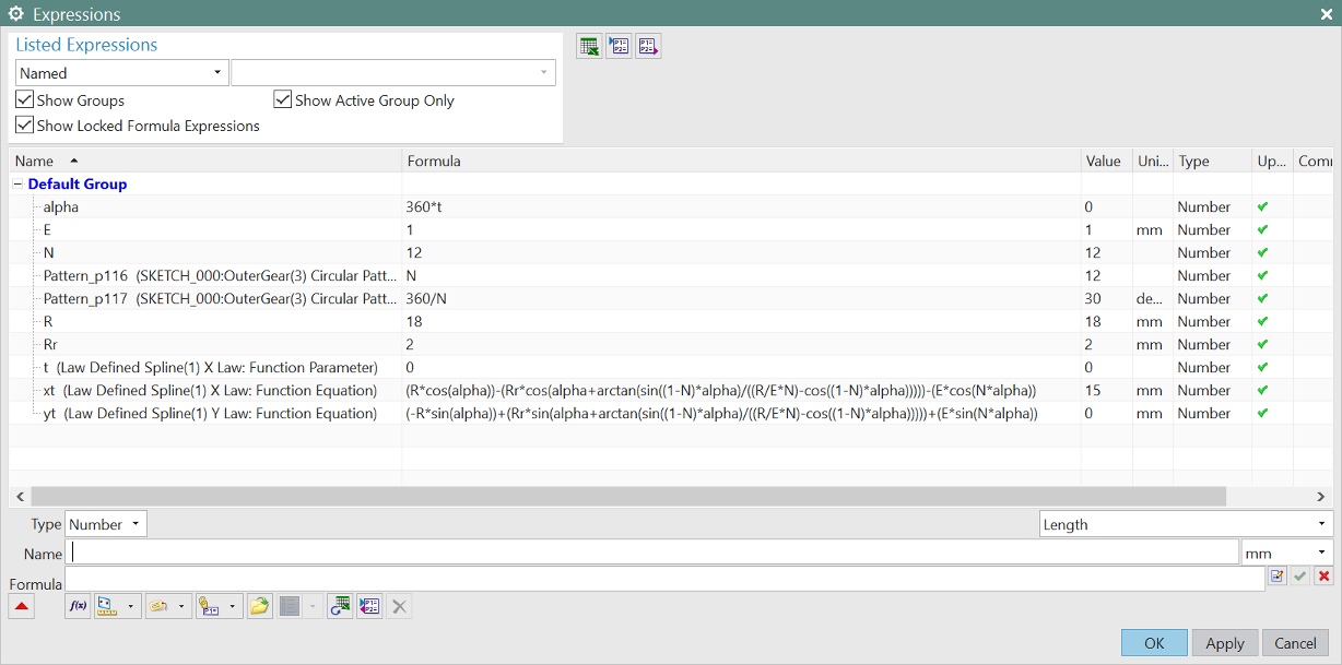
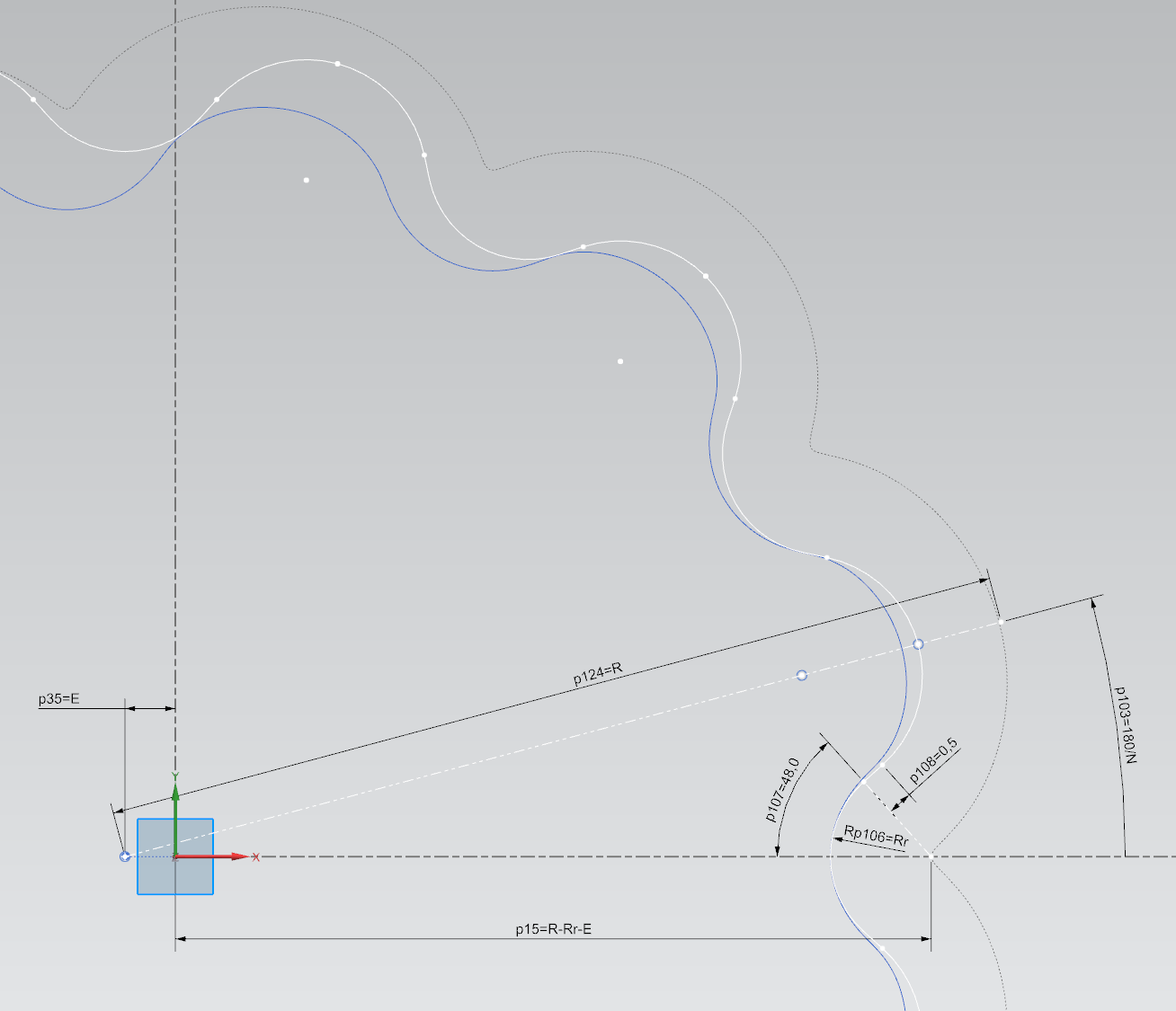
Redesigning is still the best CAD translation method -
Driving variables for the equations: R=18, E=1.0, Rr=2.0, N=12
From the equations driven curve (dotted curve) an offset curve to the inside with distance=Rr needs to be created (this is not really mentioned in the SolidWorks guide...). The result will be the theoretical excenter gear profile (blue).
The ring gear profile (white) is created from the pin-arcs (radius=Rr), connected by some simple sketch curves - please see attached file.
To cover the gears' clearance, an offset to the theoretical excenter gear profile by 0.05mm was done.
|
Re: This engineer claims 100 grams direct extruder. I want one June 22, 2016 01:01PM |
Registered: 8 years ago Posts: 93 |
|
Re: This engineer claims 100 grams direct extruder. I want one June 23, 2016 11:28AM |
Registered: 8 years ago Posts: 93 |
I think the software we use handles things differently, here I've put in the numbers you gave(blue line), then offset it by 2mm(black line).
Then I've overlaid the STL file(orange) and they don't line up.
If I use R=16 it lines up perfectly though(without an offset).
Then I've overlaid the STL file(orange) and they don't line up.

If I use R=16 it lines up perfectly though(without an offset).
|
Re: This engineer claims 100 grams direct extruder. I want one June 23, 2016 01:52PM |
Registered: 8 years ago Posts: 62 |
Quote
asbo
I think the software we use handles things differently, here I've put in the numbers you gave(blue line), then offset it by 2mm(black line).
Then I've overlaid the STL file(orange) and they don't line up.
[attachment 80268 offsetwithoverlay.jpg]
If I use R=16 it lines up perfectly though(without an offset).
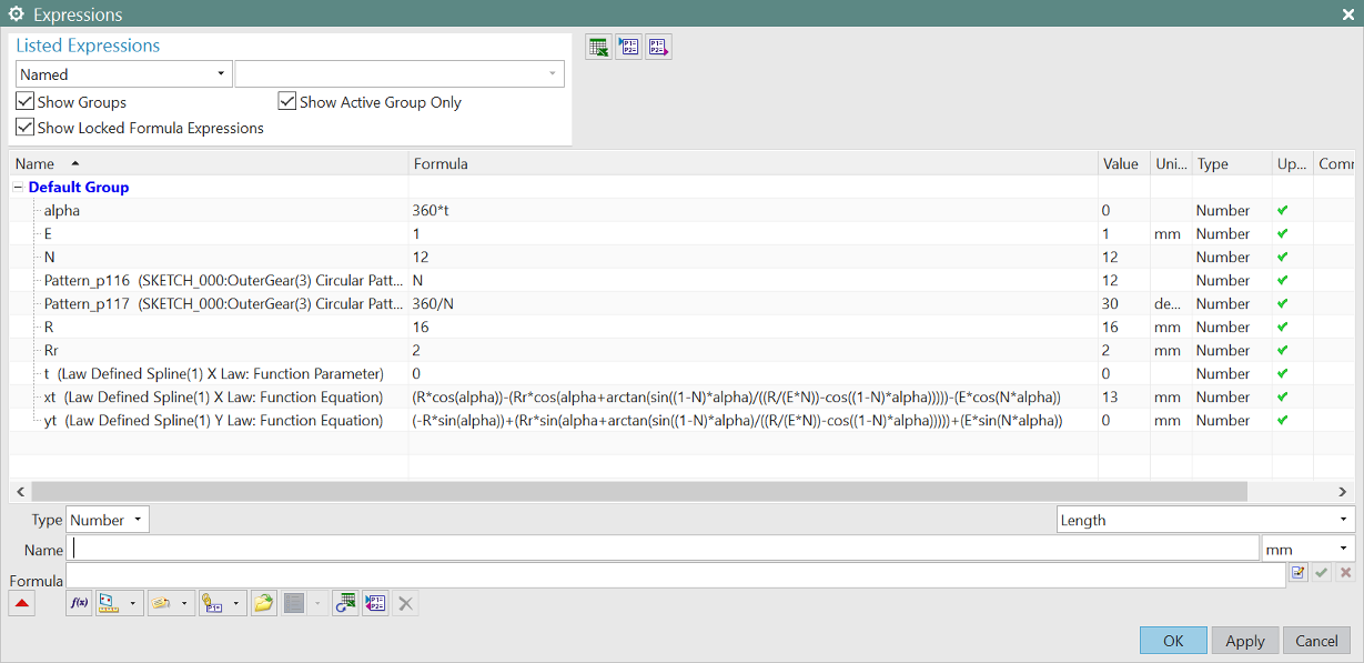
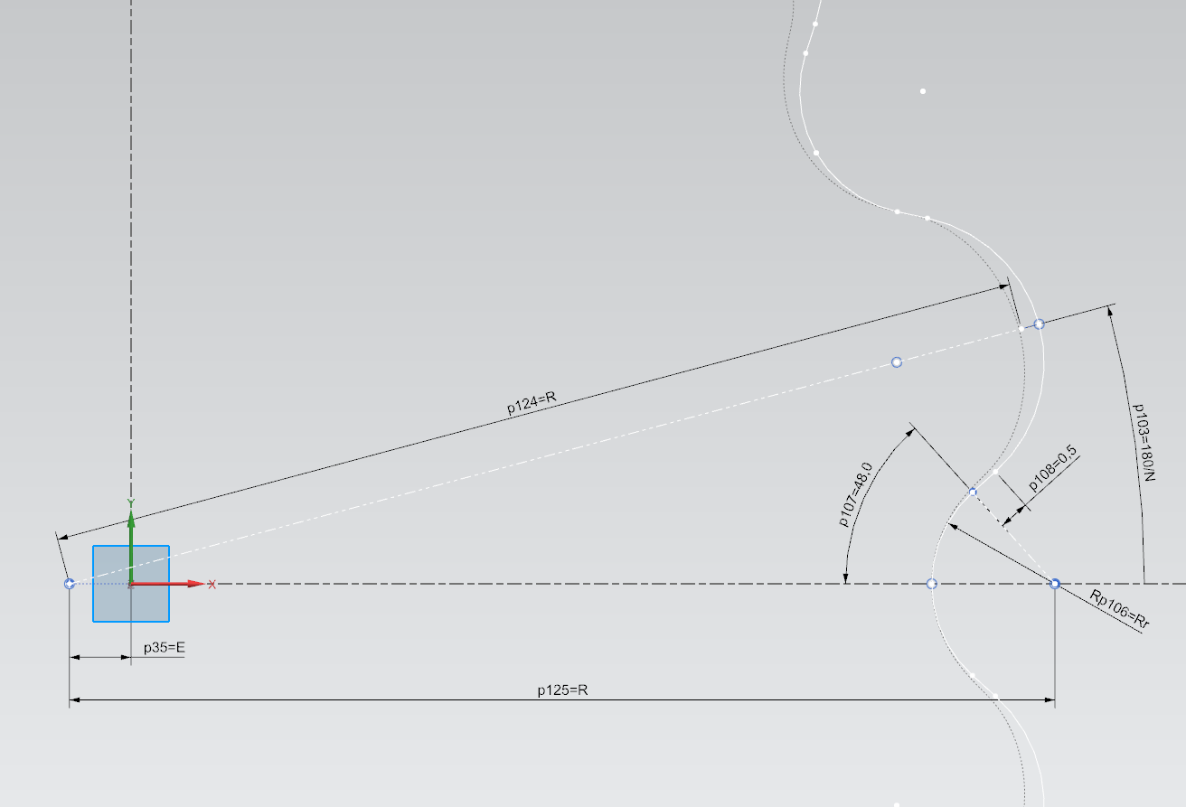
Math is everywhere the same on this planet - and so you are right: There was a bug in my equations!

The "(R/EN)" from the SolidWorks guide has to be interpreted as "(R/(E*N))" - arghhh!
Now:
Driving variables for the equations: R=16, E=1.0, Rr=2.0, N=12
The equations driven curve (dotted curve) is the theoretical excenter gear profile. The ring gear profile (white) is created from the pin-arcs (radius=Rr), connected by some simple sketch curves.
Thanks for supporting!
PS: The maximum difference between the incorrect and the correct profile is 0.006mm - so there will be no noticeable error from this. However I will include the correct equations in the upcoming v0.4...
|
Re: This engineer claims 100 grams direct extruder. I want one June 23, 2016 04:26PM |
Registered: 8 years ago Posts: 93 |
|
Re: This engineer claims 100 grams direct extruder. I want one July 03, 2016 10:22AM |
Registered: 8 years ago Posts: 5,232 |
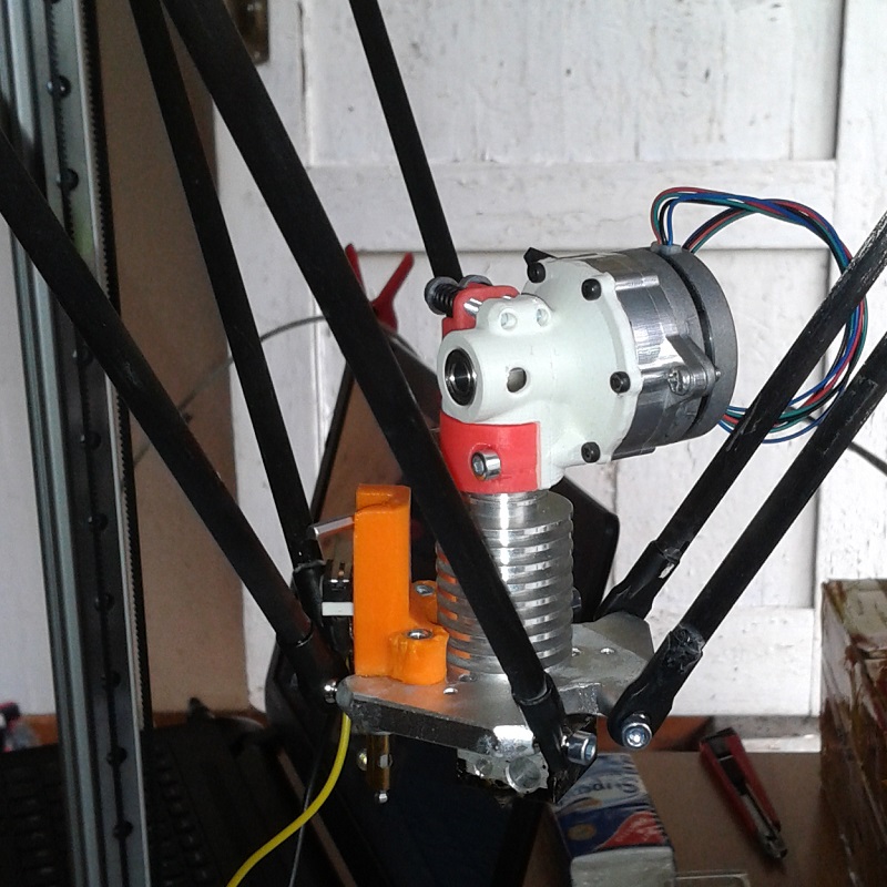
To push up this thread I want to show my version of the cycloid extruder.
The drive parts were milled from aluminum and POM by a workmate.
The coldend was modified to fit the robotdigg effector.
Unfortunately the excenter got to hot after a 2h testrun without cooling and melted. ( ~ 350mA driver current )
We are currently working on an aluminum version from the lathe.
I made a testrun with my delta at 15000mm/min which went pretty good. Soon a real print will show any ringing in the mechanics or underextrusion.
-Olaf
|
Re: This engineer claims 100 grams direct extruder. I want one July 03, 2016 03:27PM |
Registered: 8 years ago Posts: 62 |
Incredible - great job - you are pushing in fact!
Going for machined components is actually the next step: FDM-printed gears are simply not precise enough for high quality motion transmission.
Your ring gear seems to be made from aluminium - which components did you make from POM and what's your experience from that?
Did you print the excenter and if so, from what material?
Best regards to your machining workmate - well done!
|
Re: This engineer claims 100 grams direct extruder. I want one July 03, 2016 04:43PM |
Registered: 8 years ago Posts: 3,525 |
What do the extruder and motor weigh?
250mm/s sounds great, what acceleration are you using?
How can the part that melted be prevented from doing so, make it out of nylon/metal?
Simon Khoury
Co-founder of [www.precisionpiezo.co.uk] Accurate, repeatable, versatile Z-Probes
Published:Inventions
250mm/s sounds great, what acceleration are you using?
How can the part that melted be prevented from doing so, make it out of nylon/metal?
Simon Khoury
Co-founder of [www.precisionpiezo.co.uk] Accurate, repeatable, versatile Z-Probes
Published:Inventions
|
Re: This engineer claims 100 grams direct extruder. I want one July 04, 2016 10:45AM |
Registered: 8 years ago Posts: 5,232 |
Quote
DjDemonD
What do the extruder and motor weigh?
250mm/s sounds great, what acceleration are you using?
How can the part that melted be prevented from doing so, make it out of nylon/metal?
Will weight it tomorrow, we could easily shave off some aluminum, but the first sample is just for experimenting and proof of concept.
250mm/s @3000mm/s² was just the delta moving with the weight of the extruder on the effector. It doesn't mean we can expect to print with that speed, but the mechanics are stable enough to deal with the direct drive at such speeds.
Nylon is even harder to print. We tried with 0.4 and 0.3mm nozzle, but the excenter is so tiny, it just looks like a piece of poodle crap
I made mine from TPA/TPE a highly flexible filament. It melted and cured again after a cooling pause. Something you don't want in a longer print. So cooling the stepper is mandatory. I'll try to make a combined cooler for the stepper and coldend to safe weight.
Another option to make a better excenter, is to skip the bearings and let the POM-part act as glide bearing. Or use a thin brass tube as bearing?
|
Re: This engineer claims 100 grams direct extruder. I want one July 04, 2016 01:17PM |
Registered: 8 years ago Posts: 62 |
Quote
o_lampe
Quote
DjDemonD
What do the extruder and motor weigh?
250mm/s sounds great, what acceleration are you using?
How can the part that melted be prevented from doing so, make it out of nylon/metal?
Will weight it tomorrow, we could easily shave off some aluminum, but the first sample is just for experimenting and proof of concept.
250mm/s @3000mm/s² was just the delta moving with the weight of the extruder on the effector. It doesn't mean we can expect to print with that speed, but the mechanics are stable enough to deal with the direct drive at such speeds.
Nylon is even harder to print. We tried with 0.4 and 0.3mm nozzle, but the excenter is so tiny, it just looks like a piece of poodle crap
I made mine from TPA/TPE a highly flexible filament. It melted and cured again after a cooling pause. Something you don't want in a longer print. So cooling the stepper is mandatory. I'll try to make a combined cooler for the stepper and coldend to safe weight.
Another option to make a better excenter, is to skip the bearings and let the POM-part act as glide bearing. Or use a thin brass tube as bearing?
The v0.3 eccentric part is in fact difficult to print: The smallest wall thickness is 0.44mm. With the next version, the eccentricity will be reduced, giving more wall thickness (0.67mm) and good printability even with 0.4mm nozzles. For avoiding "poodle crap", tune your machine for max cooling or print 2 pieces at the same time.
Skipping the bearings would for sure save lots of space in the assembly and help for the wall thickness issues. However you should be aware of all the energy dissipated from "high speed" sliding with pressure in the gliding zone. I had done that for a small cyclo gearbox for a toy car and was not happy with the results. Maybe we should give it another try...
Using a flexible filament: What's the intent behind that?
|
Re: This engineer claims 100 grams direct extruder. I want one July 05, 2016 12:46PM |
Registered: 8 years ago Posts: 5,232 |
|
Re: This engineer claims 100 grams direct extruder. I want one July 06, 2016 10:58AM |
Registered: 8 years ago Posts: 93 |
This is what I've modelled so far. Spent far too long messing around trying to get the gears to mate properly, which is kinda pointless but oh well 
@powdermetal Could you upload this part with the chamfers and fillets disabled/removed please? I'm finding it too difficult to reverse engineer.

@powdermetal Could you upload this part with the chamfers and fillets disabled/removed please? I'm finding it too difficult to reverse engineer.

|
Re: This engineer claims 100 grams direct extruder. I want one July 06, 2016 11:30AM |
Registered: 8 years ago Posts: 5,232 |
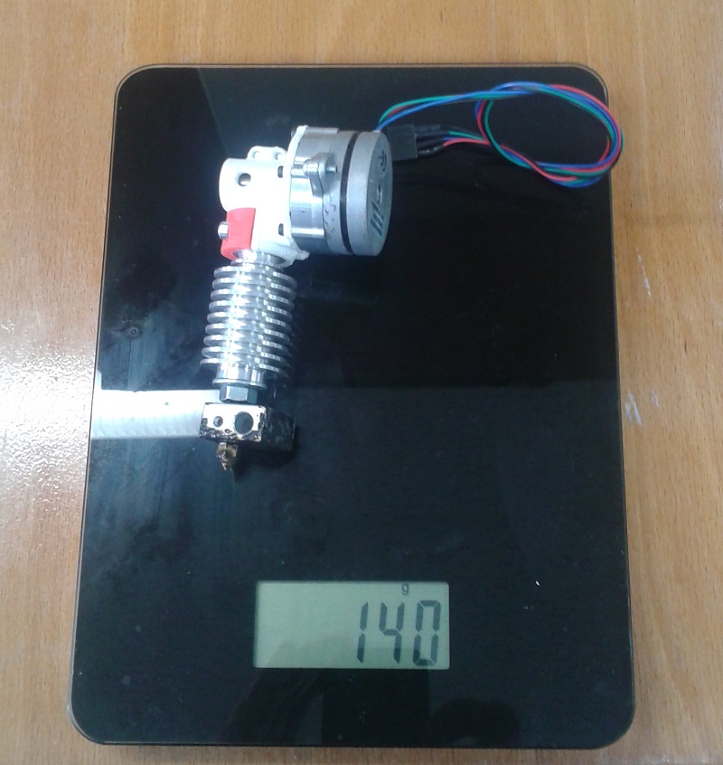
Here are the promised weight and excenter pics. 140gr is not much more than the all_plastic version.
The excenter is now fastened with a M2 set screw. Probably we need to drill a hole in the housing to fasten it. But for the bravehearts, glue is another option.
My workmate has proven his geniality by making it from one_piece on the lathe. This excenter would cost more than all the other parts together.
Edited 1 time(s). Last edit at 07/06/2016 11:33AM by o_lampe.
|
Re: This engineer claims 100 grams direct extruder. I want one July 07, 2016 01:19PM |
Registered: 8 years ago Posts: 62 |
Quote
asbo
This is what I've modelled so far. Spent far too long messing around trying to get the gears to mate properly, which is kinda pointless but oh well
[attachment 80863 sofar.jpg]
@powdermetal Could you upload this part with the chamfers and fillets disabled/removed please? I'm finding it too difficult to reverse engineer.
[attachment 80861 thisminusfillets.jpg]
Mating: Are you trying to mate the components by their surfaces? Mating by aligning components' datum planes/datum axis to each other in the assembly positions things independently of their outer shape and there are no problems with curved faces. Anyway, I see you are making good progress
 .
.Attached you will find a simplified model with removed blends/chamfers - hope this helps.
Edited 1 time(s). Last edit at 07/07/2016 01:54PM by powdermetal.
|
Re: This engineer claims 100 grams direct extruder. I want one July 07, 2016 02:01PM |
Registered: 8 years ago Posts: 62 |
Quote
o_lampe
Here are the promised weight and excenter pics. 140gr is not much more than the all_plastic version.
The excenter is now fastened with a M2 set screw. Probably we need to drill a hole in the housing to fasten it. But for the bravehearts, glue is another option.
My workmate has proven his geniality by making it from one_piece on the lathe. This excenter would cost more than all the other parts together.
Great job - turning a double eccentric pin needs advanced machining skills - looks very professional!
Looking forward to hear about your printing results...
|
Re: This engineer claims 100 grams direct extruder. I want one July 07, 2016 02:05PM |
Registered: 8 years ago Posts: 93 |
Thanks for the file
Mating: Apparently the way Cam mates work in Solidworks has changed since that .pdf guide was made, the cam mate must now be a continuous surface. So the gear with it's 0 - 180 degrees equation driven curve and it's mirror can't be mated since Solidworks doesn't see them as continuous. I got around this by fitting a spline to those two curves, although a spline is inaccurate I think it's near enough (0.00007mm). I think I've got it working, it was just a bit confusing.
Mating: Apparently the way Cam mates work in Solidworks has changed since that .pdf guide was made, the cam mate must now be a continuous surface. So the gear with it's 0 - 180 degrees equation driven curve and it's mirror can't be mated since Solidworks doesn't see them as continuous. I got around this by fitting a spline to those two curves, although a spline is inaccurate I think it's near enough (0.00007mm). I think I've got it working, it was just a bit confusing.
|
Re: This engineer claims 100 grams direct extruder. I want one July 09, 2016 02:53PM |
Registered: 8 years ago Posts: 62 |
The Cycloidal Extruder Drive v0.4 has been released to solve some previous issues:
More images and movies: Build v0.4: Google Album
Long term durability has still to be proven, however after 12 hours printing v0.3 shows no signs of wear on the teeth surfaces nor at the pin holes. So the simple kind of plastics we use here seem to be sufficient.
For better surface appearance of printed parts with this drive unit there is lots of potential by making the gears, the eccentric and the output hub by precision machining - looking forward, what o_lampe's results will be.
- No more lost steps when extruding material from the printer controller - gear ratio changed to 16:1
- Printing the eccentric is now much easier with a standard FDM-printer with a 0.4mm nozzle
- Assembly of the gearbox is less fuzzy


More images and movies: Build v0.4: Google Album
Long term durability has still to be proven, however after 12 hours printing v0.3 shows no signs of wear on the teeth surfaces nor at the pin holes. So the simple kind of plastics we use here seem to be sufficient.
For better surface appearance of printed parts with this drive unit there is lots of potential by making the gears, the eccentric and the output hub by precision machining - looking forward, what o_lampe's results will be.
|
Re: This engineer claims 100 grams direct extruder. I want one August 05, 2016 05:51AM |
Registered: 8 years ago Posts: 5,232 |
I ran my V0.3 for several hours and can only repeat what powdermetal said about durability and wear, but on the retraction side I have to admit defeat. 
I'm not able to retract faster than 40mm/s reliably and this results in stringy prints and occasional underextrusion after retracts even worse than with a Bowden setup.
The retraction is done at full current ( 0.5A ) with 1/16 microsteps on RAPS128 drivers with a 24V RADDS 32 bit CPU. This is more than 3300 steps/mm. You can't retract that fast with an 8-bit CPU@12V, if anyone was wondering.
It seems the NEMA11 pancake has sufficient torque at slow speed, but looses torque at higher RPM pretty fast. ( even at 24V )
So in the end there is no benefit for my delta. I can have crappy retracts with a Bowden too and it will be less top heavy on my effector.
Maybe with a lower gear ratio than 1/12 and using less microsteps it'll work better, but then the cycloid gear no longer has a meaning. They are meant to have high gear ratios to run smooth.
-Olaf
A pic of my ( best ) print results, the unsuccessful ones are building a pile on the floor
TBH, not all the failed prints are caused by the extruder, many of them happened while I calibrated the all_new delta.
Edited 2 time(s). Last edit at 08/05/2016 07:12AM by o_lampe.
|
Re: This engineer claims 100 grams direct extruder. I want one August 05, 2016 10:21AM |
Registered: 8 years ago Posts: 916 |
|
Re: This engineer claims 100 grams direct extruder. I want one August 05, 2016 02:23PM |
Registered: 8 years ago Posts: 5,232 |
|
Re: This engineer claims 100 grams direct extruder. I want one August 05, 2016 05:25PM |
Registered: 8 years ago Posts: 62 |
Quote
o_lampe
I ran my V0.3 for several hours and can only repeat what powdermetal said about durability and wear, but on the retraction side I have to admit defeat.
I'm not able to retract faster than 40mm/s reliably and this results in stringy prints and occasional underextrusion after retracts even worse than with a Bowden setup.
The retraction is done at full current ( 0.5A ) with 1/16 microsteps on RAPS128 drivers with a 24V RADDS 32 bit CPU. This is more than 3300 steps/mm. You can't retract that fast with an 8-bit CPU@12V, if anyone was wondering.
It seems the NEMA11 pancake has sufficient torque at slow speed, but looses torque at higher RPM pretty fast. ( even at 24V )
Maybe the 40mm/sec will be exhausting for the controller and way too aggressive for the motor/gearbox combo:
- 40mm/sec x 3300 E-steps/mm means 132000 E-steps/sec. My Azteeg X5 (32-bit) running Smoothie is configured to "base_stepping_frequency=100000", so I could never do 40mm/sec from the controller without stumbling.
- 40mm/sec filament-speed means approx. 2 revolutions/sec for the MK8 gear. With a transmission ratio of 12:1, this results in 24 revs/sec for the stepper motor. Looking at some better documented industrial steppers and comparing them, I suppose the NEMA 14 pancake can never do that...
I am running the drive unit with 10mm/sec (actually started with 5mm/sec, which was fine as well regarding stringing) and a retract distance of 0.5mm.
Time/distance for a retract operation - assuming a configured acceleration of 1000mm/sec^2 - will be:
- accelerate: 0...10mm/sec: 0.01sec, 0.05mm
- constant speed: 10mm/sec: 0.04mm, 0.4mm
- decelerate: 10...0mm/sec: 0.01sec, 0.05mm
Now do the same calculation with my (non stringing) bowden setup, MK8 gear directly mounted to the stepper shaft, retract=3mm, speed=60mm/sec, acceleration=4000mm/sec^2:
- accelerate: 0...60mm/sec: 0.015sec, 0.45mm
- constant speed: 60mm/sec: 0.035mm, 2.1mm
- decelerate: 60...0mm/sec: 0.015sec, 0.45mm
Rethinking all this, I have serious doubts, whether an acceleration of 1000mm/sec^2 will even work without already loosing steps...
Anyway, an extruder next to the hotend needs different parameters and maybe you want to give "slow" speeds like 5mm/sec and low accelerations a chance.
BTW: Nice combo of controller board and motor drivers!
Edited 1 time(s). Last edit at 08/05/2016 05:30PM by powdermetal.
|
Re: This engineer claims 100 grams direct extruder. I want one August 05, 2016 05:26PM |
Registered: 10 years ago Posts: 14,672 |
What is the inductance of your Nema 11 motor? Can you get a variant that has a higher rated current but lower inductance?
Large delta printer [miscsolutions.wordpress.com], E3D tool changer, Robotdigg SCARA printer, Crane Quad and Ormerod
Disclosure: I design Duet electronics and work on RepRapFirmware, [duet3d.com].
Large delta printer [miscsolutions.wordpress.com], E3D tool changer, Robotdigg SCARA printer, Crane Quad and Ormerod
Disclosure: I design Duet electronics and work on RepRapFirmware, [duet3d.com].
|
Re: This engineer claims 100 grams direct extruder. I want one August 05, 2016 05:47PM |
Registered: 8 years ago Posts: 62 |
Quote
dc42
What is the inductance of your Nema 11 motor? Can you get a variant that has a higher rated current but lower inductance?
The employed NEMA 14 14HR05-0504S has an inductance of 7.5mH.
There are a bunch of "better" motors for these properties out there, but this one seems to have the most favorable torque/weight ratio for this application - at least, which has come to my attention. Let's see, how it works out at o_lampe.
Edited 1 time(s). Last edit at 08/05/2016 05:54PM by powdermetal.


Sorry, only registered users may post in this forum.