What would be a good mechanism for automatically swapping working heads for Cartesian 3d printers?
Posted by realthor
|
What would be a good mechanism for automatically swapping working heads for Cartesian 3d printers? February 06, 2016 07:13AM |
Registered: 9 years ago Posts: 1,035 |
Deltas can get the effector out of their printing space and potentially grab new tools to use but for Cartesian i haven't seen so far many attempts to develop a tool changing mechanism so I am throwing it out here.
What would be a good mechanism for automatically swapping working heads for Cartesian 3d printers?
Personally I am thinking about CoreXY because these printers can be easily enclosed making them a good choice for milling operations, laser cutting, etc. My idea revolves around a star mechanism that can rotate and insert one arm of the star inside the printing area so that the XY carriage can reach it and swap tools by some mechanism, possibly compressed air-based (or magnets but only for lighter heads I would guess). Then, when the bed descend completely to allow part removal, it can trigger a lever of sorts that when repeatedly pressed by raising and lowering the bed cycles through the different tools placed on the star's arms by rotating one at a time.
What are your ideas for tool changing heads and what heads are you thinking of being useful to the actual 3d printers we have? If you have any paper towel drawing at all please share.
One note: I believe the FDM printers will only survive if they evolve in multi-tool desktop-factories that can create a lot of objects with a minimum amount of tool-heads.
RepRap Lander concept on Concept Forge
RepRap Lander concept on RepRap Forums
My Things, mostly experimental stuff
|
Re: What would be a good mechanism for automatically swapping working heads for Cartesian 3d printers? February 06, 2016 08:35AM |
Registered: 12 years ago Posts: 2,470 |
I thought about this for a few months and in the end went for a classic cartesian printer with two x carriages. Maybe you have or get better ideas than i did, but nothing i could think of was really useful.
[www.bonkers.de]
[merlin-hotend.de]
[www.hackerspace-ffm.de]
[www.bonkers.de]
[merlin-hotend.de]
[www.hackerspace-ffm.de]
|
Re: What would be a good mechanism for automatically swapping working heads for Cartesian 3d printers? February 06, 2016 11:33AM |
Registered: 12 years ago Posts: 1,450 |
I have been trying for some time to do make just such a mechanism to swap working heads for a printer. Like you I think that the next logical direction for an FDM printer to go in is to have additional functions - such as placing components - e.g. nuts into cavities, electronic components etc..
The approach I decided upon was to have the bed moving in both the X and the Y axis while a bunch of heads would move only in the Z axis. Printing heads would be moved on an axis paralell to one axis - I call this the X prime (X') axis. Unused print heads would be lifted out of the way to stop nozzles etc. from dragging on the print
While the XY mechanism was built and works well, the head swapping mechanism is on its fifth iteration - with each try coming up against one problem or another.
The XY menanism can be seen in a video that I put on Youtube [www.youtube.com]
The first try was the closest to success and involved one stepper motor to drive the extruders and to change their position. In the rendering below (itteration 3), three of the extruders had been moved off the carriage to feed through short bowden tubes
The lift mechanism for lifting the hotends and extruders is shown in a 3D view below
All of my attempts so far have used a very well proven extruder, but even the bulk of this very tiny extruder has been too much to get 5 on the X' carriage.
A bunch of extruders with 3 set up for the short bowdens below.
The next try will either come back to the first method but with only three extruders, or will involve a new extruder design completely. Most of the good work was done 18 months ago) [forums.reprap.org] ) so the light at the end of the tunnel, and the enthusiasm, are only dim and flickering now
The approach I decided upon was to have the bed moving in both the X and the Y axis while a bunch of heads would move only in the Z axis. Printing heads would be moved on an axis paralell to one axis - I call this the X prime (X') axis. Unused print heads would be lifted out of the way to stop nozzles etc. from dragging on the print
While the XY mechanism was built and works well, the head swapping mechanism is on its fifth iteration - with each try coming up against one problem or another.
The XY menanism can be seen in a video that I put on Youtube [www.youtube.com]
The first try was the closest to success and involved one stepper motor to drive the extruders and to change their position. In the rendering below (itteration 3), three of the extruders had been moved off the carriage to feed through short bowden tubes

The lift mechanism for lifting the hotends and extruders is shown in a 3D view below

All of my attempts so far have used a very well proven extruder, but even the bulk of this very tiny extruder has been too much to get 5 on the X' carriage.
A bunch of extruders with 3 set up for the short bowdens below.

The next try will either come back to the first method but with only three extruders, or will involve a new extruder design completely. Most of the good work was done 18 months ago) [forums.reprap.org] ) so the light at the end of the tunnel, and the enthusiasm, are only dim and flickering now
|
Re: What would be a good mechanism for automatically swapping working heads for Cartesian 3d printers? February 06, 2016 09:22PM |
Registered: 9 years ago Posts: 1,873 |
|
Re: What would be a good mechanism for automatically swapping working heads for Cartesian 3d printers? February 06, 2016 11:08PM |
Registered: 8 years ago Posts: 1,671 |
|
Re: What would be a good mechanism for automatically swapping working heads for Cartesian 3d printers? February 07, 2016 01:09AM |
Registered: 9 years ago Posts: 1,035 |
@Mike: I agree with James that's a very advanced solution you have there. I really wish there was a way to lend capable people some enthusiasm. It's very difficult to keep it up in such pioneering industries like 3d printing and there are highs and lows all the time.
I am only starting to think about such a solution and have been looking in the CNC world where there are many such solutions of automatically changing working heads but yours seem a well thought one.
Edited 1 time(s). Last edit at 02/07/2016 01:09AM by realthor.
RepRap Lander concept on Concept Forge
RepRap Lander concept on RepRap Forums
My Things, mostly experimental stuff
|
Re: What would be a good mechanism for automatically swapping working heads for Cartesian 3d printers? February 07, 2016 05:34AM |
Registered: 12 years ago Posts: 1,450 |
One problem with using designs from the CNC world is that there may be a number of swaps between heads on a single layer and these may need to be rapid. An example is in laying down support material where a layer may involve two heads for perhaps the larger part of the print. Mixed materials like building flexible hinge material into a rigid part are another example - adding a different colour and there could be four heads being swapped between for each layer.
A good method may be like Srek's design with two X carriages, but with swap-out mechanisms on one or both ends so that while one head is printing another may be swapped out.
The simple swaping of entire heads is no mean task though, remember that it may involve not just a heater element and temperature sensor, but also some method of cooling the non-printing end of the nozzle, perhaps some directed air flow to cool the print and of course, wires for the extruder or a bowden tube.
A mechanism for a multi headed design could be beguilingly simple, but the sorts of problems that it introduces soon get to be endless. Hopefully the inner glow from getting it all working will be satisfaction enough.
Mike
|
Re: What would be a good mechanism for automatically swapping working heads for Cartesian 3d printers? February 07, 2016 12:11PM |
Registered: 9 years ago Posts: 1,035 |
Quote
leadinglights
One problem with using designs from the CNC world is that there may be a number of swaps between heads on a single layer and these may need to be rapid. An example is in laying down support material where a layer may involve two heads for perhaps the larger part of the print. Mixed materials like building flexible hinge material into a rigid part are another example - adding a different colour and there could be four heads being swapped between for each layer.
A good method may be like Srek's design with two X carriages, but with swap-out mechanisms on one or both ends so that while one head is printing another may be swapped out.
The simple swaping of entire heads is no mean task though, remember that it may involve not just a heater element and temperature sensor, but also some method of cooling the non-printing end of the nozzle, perhaps some directed air flow to cool the print and of course, wires for the extruder or a bowden tube.
A mechanism for a multi headed design could be beguilingly simple, but the sorts of problems that it introduces soon get to be endless. Hopefully the inner glow from getting it all working will be satisfaction enough.
Mike
I understand your point of view and you are totally right. But my pov is that 3D printing is one tool, hence all 3D printer heads should be one single tool. Another head would be laser cutter, another head would be calibration/edge detection/etc, another head would be milling for the sturdy printers that can take that beating, another would be polishing/buffing ...etc.
I don't think you'll be milling while 3d printing.
I understand the complexity of even a small number of tools like some 3d printer heads and laser module. I don't plan to have more than 2 hotends on my x carriage. I believe the coloring should be handled in the nozzle via inks, not a gazillion colours filaments. Even cutting and fusing together filaments end to end is a better solution than having many hotends just for color. I believe I'll have 1 direct extruder for the main material and a bowden extruder for the support material. No plans for coloring at this time, I am a functionalist but I understand the necessity for other people. Having all the wires not tangle with each other in the different heads will amke one such printer look like a thread winding industrial machine.
We should also think of a standard to exchange heads, I believe that it should be independent of the X axis medium, like rods or alu profiles or rails... It should be in the mount on the carriage. A way to un-lock the previously locked mount and do a new mount and lock it in place. Ideally this will involve no additional motors or at most one (?) if possible.
I think it should also be platform-independent, being able to be fitted to Prusas and CoreXYs alike ...that may be a stretch though.
I was thinking of a penumatic way to exchange heads because that has the potential of a clever motorless tool swap. Push to open a valve, air pressure hits some fans or some sort of built-in impeller that rotates the tool unscrewing it from the carriage and screwing it on the tool exchanger, tool exchanger rotates and presents another tool to the carriage, carriage pushes agains it once more, the same valve opens and air pressure is used to rotate the other way, unscrewing the tool from the head exchanger and screwing it onto the carriage. This is a very high-level example just to show a proof of concept may be naively simple and unrealistic...still it's just to point one direction.
Also having a pressurized tank will store the energy of a motor that will be able to be used to fill another tanks while the pressurized air works its magic and will not sit idle on the machine waiting for a tool to be exchanged.
But I am pretty sure my skills will not help me to design such a pneumatic exchanger alone. Also if the vast majority of true engineers and makers here will disagree then I'll drop it as I don't have the skills to pursue this on my own
 .
.Edited 2 time(s). Last edit at 02/07/2016 12:47PM by realthor.
RepRap Lander concept on Concept Forge
RepRap Lander concept on RepRap Forums
My Things, mostly experimental stuff
|
Re: What would be a good mechanism for automatically swapping working heads for Cartesian 3d printers? February 07, 2016 01:03PM |
Registered: 9 years ago Posts: 1,035 |
What I see is that many high-end (?) machines use this type of tool exchanger: https://www.youtube.com/watch?v=ZyyqOfUsvnY&feature=youtu.be&t=36. I have no idea what it involves, if the sounds mean pressured air escaping (and involved in the swap) ...
RepRap Lander concept on Concept Forge
RepRap Lander concept on RepRap Forums
My Things, mostly experimental stuff
RepRap Lander concept on Concept Forge
RepRap Lander concept on RepRap Forums
My Things, mostly experimental stuff
|
Re: What would be a good mechanism for automatically swapping working heads for Cartesian 3d printers? February 07, 2016 01:36PM |
Registered: 12 years ago Posts: 1,450 |
Just to pick up on one point - there are too many to address everything.
If colour is the object in having more than one head then an external machine that cuts lengths of filament and welds them would be a good start. However, I am not too artistic and multicoloured Yodas are only of passing interest. When it comes to multiple material printers however, you would have my full attention. Consider a prosthetic hand - if this is to be printed in one piece there would need to be rigid materials for the bones, flexible materials for the joints, a different flexible material with a high tensile strength for the tendons along with a dissoluble support material so that parts could have a more natural form. Four materials there alone - a fifth to cover anything I had not thought of would seem to be a minimum.
With sufficient inventiveness a great deal can be accomplished - even the suggestion that a simple 3D printer could be made by a private individual within a hobby budget was unthinkable to most a few years ago. Having said that, even a 5 head 3D printer is terrifying enough for me.
Mike
|
Re: What would be a good mechanism for automatically swapping working heads for Cartesian 3d printers? February 07, 2016 02:27PM |
Registered: 9 years ago Posts: 1,035 |
Quote
leadinglights
Just to pick up on one point - there are too many to address everything.
If colour is the object in having more than one head then an external machine that cuts lengths of filament and welds them would be a good start. However, I am not too artistic and multicoloured Yodas are only of passing interest. When it comes to multiple material printers however, you would have my full attention. Consider a prosthetic hand - if this is to be printed in one piece there would need to be rigid materials for the bones, flexible materials for the joints, a different flexible material with a high tensile strength for the tendons along with a dissoluble support material so that parts could have a more natural form. Four materials there alone - a fifth to cover anything I had not thought of would seem to be a minimum.
With sufficient inventiveness a great deal can be accomplished - even the suggestion that a simple 3D printer could be made by a private individual within a hobby budget was unthinkable to most a few years ago. Having said that, even a 5 head 3D printer is terrifying enough for me.
Mike
My personal experience is that we are still in the age of multiple-parts end-products and that is a good philosophy from an upgrade-ability pov and many more. I wouldn't want to built a prosthetic hand in one go. The tendons will wear out and should be replaceable. The skin should be customizable to the point of it being an accessory that should be matched with the dressing and the event. People should not look at the prosthetic hands' owners with pity so these prosthetic hands should make a strong enough statement to dilute any judgmental pre-conceived thinking. There is more than engineering to a product.
This being said, I am not about colors either. I am about the basic functional part of things. Beautifying should come later (but be permitted by the design intent from the beginning)
4 heads in a 3D printer is not something unheard of. That is doable. Although the problems associated with oozing etc are not yet solved.
So I would start by defining a number of tools that the printer for non-yoda-heads-owner.
- I would choose a 3D printer tool head capable of holding 2,3 or 4 heads, no more (I am going for two, max 3) from which at least one is bowden (the support material, but maybe also the hard thermoplastic, leaving the flexible filament the direct extruder.
- I would like a laser head because they start showing up on consumer printers already (DreamMaker Overlord ex)
- I want a calibration head that is separate from the 3D printer head and that is an add-on to it (it doesn't replace it but clamps to it for said calibration)
- Now I would like a Carbon-Fibre embedding add-on to the 3D printer head (a la MakerForge), this is my lala-land but still
- I would also like a milling head that makes the printer a 5-axis milling machine (even if only light milling): this would have two mottors, one stepper motor for the 5th axis and the milling DC motor or use a flex-shaft of a rotary tool.
I don't think there is software yet that can do a couple of the above but until such big undertaking would be finished in the open-source arena for sure they would have had developed it.
Note: almost all of the above seem to be lala-land dreams but if we don't set some goals what would we expect to achieve?
Edited 2 time(s). Last edit at 02/07/2016 02:31PM by realthor.
RepRap Lander concept on Concept Forge
RepRap Lander concept on RepRap Forums
My Things, mostly experimental stuff
|
Re: What would be a good mechanism for automatically swapping working heads for Cartesian 3d printers? February 07, 2016 04:21PM |
Registered: 13 years ago Posts: 268 |
Quote
realthor
What I see is that many high-end (?) machines use this type of tool exchanger: https://www.youtube.com/watch?v=ZyyqOfUsvnY&feature=youtu.be&t=36. I have no idea what it involves, if the sounds mean pressured air escaping (and involved in the swap) ...
Each tool has a retention knob, which is gripped by hardened steel "fingers". They open and close via a sliding rod held in place with a stack of bellville washers, with a combined force of around 3000lbs on a 40 taper machine like shown. The stack is compressed with either an air/hydraulic or a hybrid system, only with the spindle stopped. When uncompressed it pulls the tool up into the taper, both locating and providing a significant portion of the friction needed to transfer power into the tool The exchange arm moves up and down and rotates typically via a complex cam gearbox that coordinates both functions but only uses one motor. There are spring loaded fingers which grip and release the tool in the arm that are locked as the arm is lowered prior to rotation. When this mechanism sticks, the machines tend to throw tools. Makes life interesting. Typical tool to tool is on the order of a few seconds, and with a random access side mount chip to chip is generally 5-10 seconds at worst at full rapids, assuming you can pre-index the next pocket. Construction of such a system further involves a number of sensor inputs to determine what part is in what position at what time, what tool pocket is where when you start from power off, and what tool has been placed in what pocket (when operated in random access mode). Compressed air is typical used to open and close the drawbar, as well as to blow off the taper during tool exchange as chips go everywhere and are problematic when they get between the tool and spindle. When you use oil lubricated spindle bearings you also typically blow air with an oil drip through the bearing to keep positive pressure coming out of the bearing and the labyrinth seal at the bottom to prevent coolant ingress into the spindle bearings.
|
Re: What would be a good mechanism for automatically swapping working heads for Cartesian 3d printers? February 07, 2016 05:59PM |
Registered: 9 years ago Posts: 1,035 |
Quote
Koko76
Quote
realthor
What I see is that many high-end (?) machines use this type of tool exchanger: https://www.youtube.com/watch?v=ZyyqOfUsvnY&feature=youtu.be&t=36. I have no idea what it involves, if the sounds mean pressured air escaping (and involved in the swap) ...
Each tool has a retention knob, which is gripped by hardened steel "fingers". They open and close via a sliding rod held in place with a stack of bellville washers, with a combined force of around 3000lbs on a 40 taper machine like shown. The stack is compressed with either an air/hydraulic or a hybrid system, only with the spindle stopped. When uncompressed it pulls the tool up into the taper, both locating and providing a significant portion of the friction needed to transfer power into the tool The exchange arm moves up and down and rotates typically via a complex cam gearbox that coordinates both functions but only uses one motor. There are spring loaded fingers which grip and release the tool in the arm that are locked as the arm is lowered prior to rotation. When this mechanism sticks, the machines tend to throw tools. Makes life interesting. Typical tool to tool is on the order of a few seconds, and with a random access side mount chip to chip is generally 5-10 seconds at worst at full rapids, assuming you can pre-index the next pocket. Construction of such a system further involves a number of sensor inputs to determine what part is in what position at what time, what tool pocket is where when you start from power off, and what tool has been placed in what pocket (when operated in random access mode). Compressed air is typical used to open and close the drawbar, as well as to blow off the taper during tool exchange as chips go everywhere and are problematic when they get between the tool and spindle. When you use oil lubricated spindle bearings you also typically blow air with an oil drip through the bearing to keep positive pressure coming out of the bearing and the labyrinth seal at the bottom to prevent coolant ingress into the spindle bearings.
Wow, thanks for the explanation. I was certain it wasn't a fairy in there doing the job. As complicated as it sounds, we don't need something like that for the immediate use of a multi-tool 3d printers (or should I call them multi-tool desktop fabricators). I was just providing some food for thought. Would you suggest anything for the tool grip/unlock-lock system in a 3D printer?
One solution for the indexing part would be that wach tool in our arsenal would have a fixed position along an axis where the X carriage can reach and get in contact with that tool-head and that contact might provide the mechanical force to unleash the much more powerful force of the compressed air. But what mechanism? My above example is a very remote example but it is something that could be done with modifications?
Edited 1 time(s). Last edit at 02/07/2016 05:59PM by realthor.
RepRap Lander concept on Concept Forge
RepRap Lander concept on RepRap Forums
My Things, mostly experimental stuff
|
Re: What would be a good mechanism for automatically swapping working heads for Cartesian 3d printers? February 08, 2016 07:05AM |
Registered: 9 years ago Posts: 1,035 |
I found one machine to look up to
https://www.youtube.com/watch?v=OohNRp65WBU
for inspiration.
Doesn't have automated tool change though
Building towards that is the FirePick Delta: https://youtu.be/rKKrY0uORLk
Another cool video i've found, one that shows kinda what I was thinking about compressed air playing the role in locking/unlocking but at a much higher engineering level
https://www.youtube.com/watch?v=IRvmR05c074
Similarily, this animation shows a flaring out system to grip the tool that works just like the previous video's bearings balls being pushed outwards:
https://youtu.be/p-8uM0qEAfc?t=53
Edited 2 time(s). Last edit at 02/08/2016 08:43AM by realthor.
RepRap Lander concept on Concept Forge
RepRap Lander concept on RepRap Forums
My Things, mostly experimental stuff
|
Re: What would be a good mechanism for automatically swapping working heads for Cartesian 3d printers? February 08, 2016 02:30PM |
Admin Registered: 13 years ago Posts: 730 |
These videos show a tool changer on an Ultimaker that appears to work quite well:
If you haven't found these old threads already, they show some design ideas that may be helpful:
If you haven't found these old threads already, they show some design ideas that may be helpful:
|
Re: What would be a good mechanism for automatically swapping working heads for Cartesian 3d printers? February 08, 2016 05:02PM |
Registered: 9 years ago Posts: 1,035 |
Quote
MattMoses
These videos show a tool changer on an Ultimaker that appears to work quite well:
If you haven't found these old threads already, they show some design ideas that may be helpful:
Very interesting links thanks for bringing them to our attention. I am actually surprised that the UM fast tool magnetic coupling was that repetable without using any "kinematic coupling" design that should have ensured going back in the same place every time. From all the others I see the preferred way of doing this for 3D printers is magnets, but most people usually talk about extruders only and how to change them around, etc.
I am not sure heavier tools and more rapid movements would be appropriate for magnet coupling. I believe not. While magnets can do a lot for light tool heads I believe a more robust system should be employed. My desktop fabricator looks like the "Limitless" machine i've linked above. I would like it to be CoreXY but Prusa style is much more closer to CNC design so I understand their choice.
So far I liked the "kinematic coupling" idea of self-aligning toll-head to tool-gripper via steel balls and groove.
Still looking for a non-magnetic way of securely attaching toolheads to the toolmount (X-carriage for most cartesian printers out there).
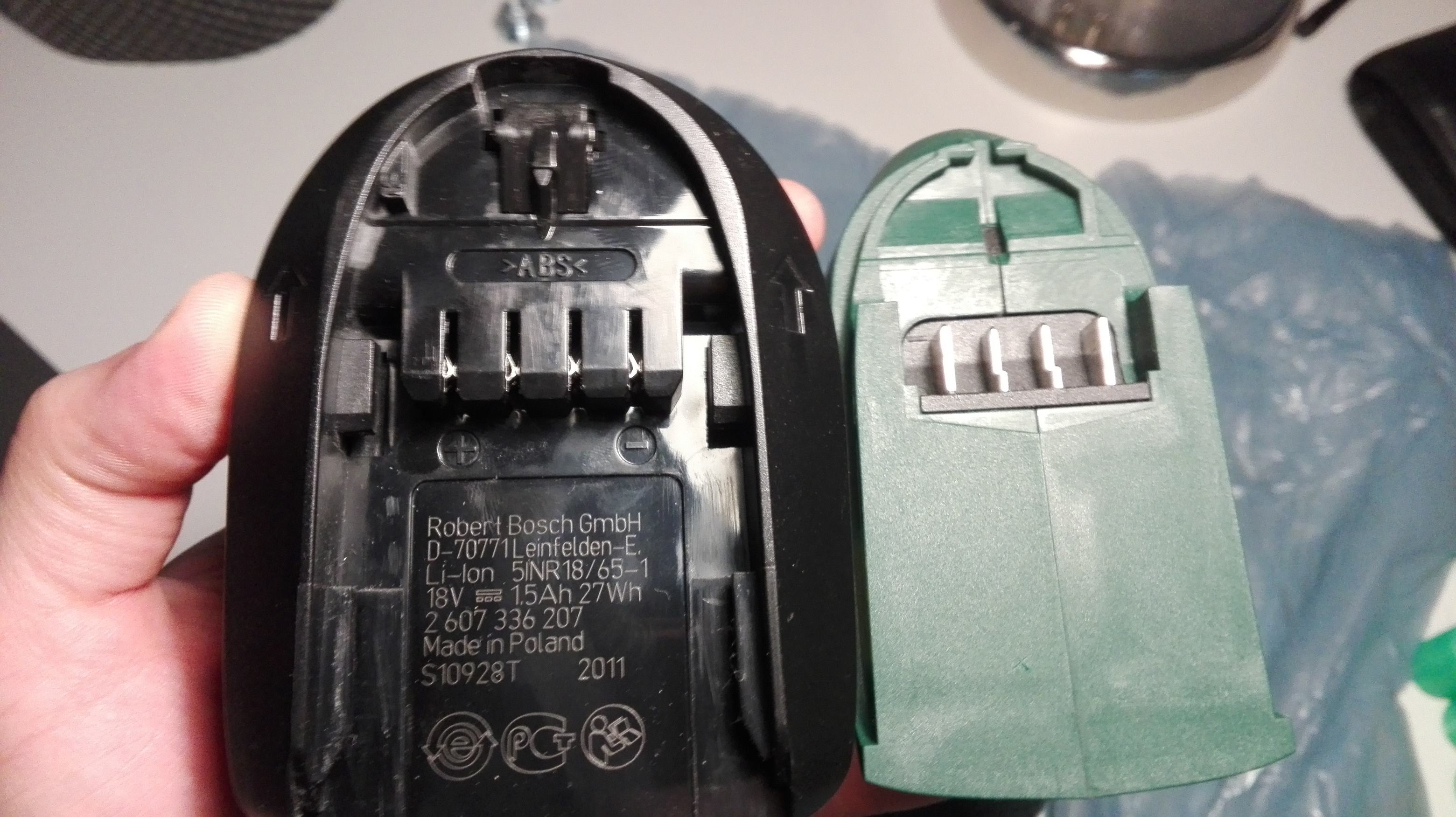
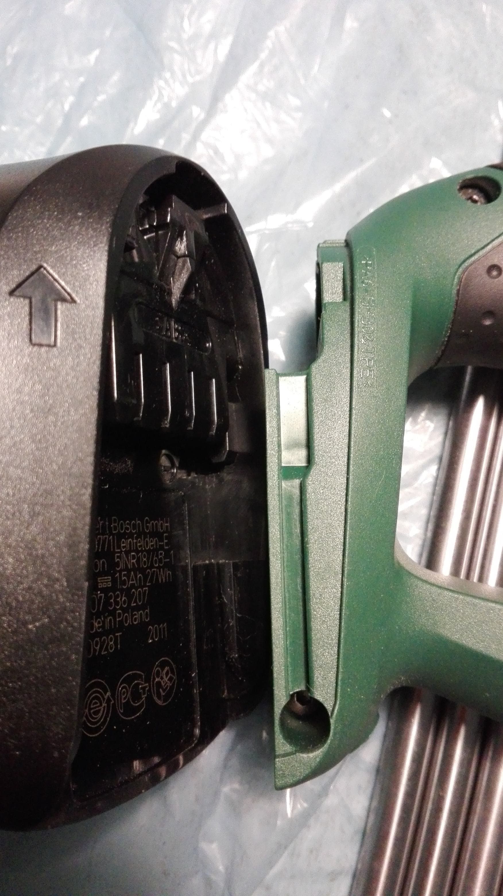
I was working today with my Cordless Drill and had to charge it after a long time (it doesn't get used too often). I realized how solid the coupling of the battery to the foot of the handle is. Basically it has no move. My particular drill is a Bosch Uneo Maxx (and I've isolated the "drill out and in" procedure from a youtube video here) but i am guessing all cordless drills have similar ways to attach the battery. And the battery is quite heavy itself. The mechanism is a pretty standard slide and snap-fit that is driven by a spring but it's robustness surprised me. You can go take a better look if you have 18V cordless drills, if the mechanics seem ok to you maybe we found a first non-magnetic contender.
Attached are some pics I took of the sliding snap-fit mechanism. @Marl: this could be adapted to your already existing mount for the lightweight extruder you've linked me to, as it already has the lips/guides it only lacks the snap-fit mechanism
.Edited 8 time(s). Last edit at 02/09/2016 08:37AM by realthor.
RepRap Lander concept on Concept Forge
RepRap Lander concept on RepRap Forums
My Things, mostly experimental stuff
Sorry, only registered users may post in this forum.