Piezoelectric disks for Z contact detect and bed levelling
Posted by leadinglights
|
Re: Piezoelectric disks for Z contact detect and bed levelling May 08, 2017 10:21AM |
Registered: 8 years ago Posts: 3,525 |
I'm sure Mike will have an idea, but piezo's are cheap - try bending a few and see what happens. That's how we developed this idea, I had no idea if you could drill one - so I drilled one.
Edited 1 time(s). Last edit at 05/08/2017 10:21AM by DjDemonD.
Simon Khoury
Co-founder of [www.precisionpiezo.co.uk] Accurate, repeatable, versatile Z-Probes
Published:Inventions
Edited 1 time(s). Last edit at 05/08/2017 10:21AM by DjDemonD.
Simon Khoury
Co-founder of [www.precisionpiezo.co.uk] Accurate, repeatable, versatile Z-Probes
Published:Inventions
|
Re: Piezoelectric disks for Z contact detect and bed levelling May 08, 2017 10:41AM |
Registered: 12 years ago Posts: 1,450 |
|
Re: Piezoelectric disks for Z contact detect and bed levelling May 11, 2017 10:35AM |
Registered: 8 years ago Posts: 916 |
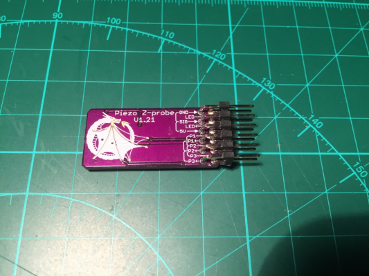
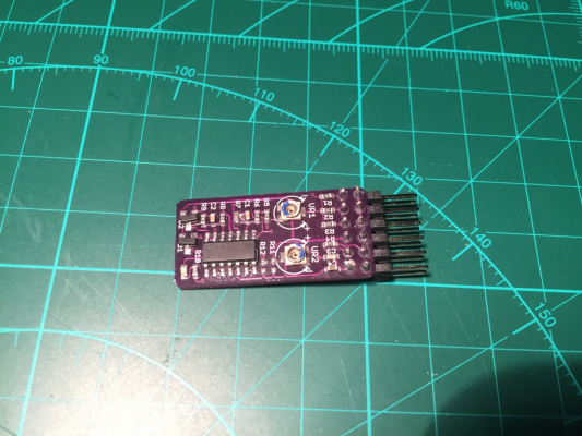
I received my sensor board today, thanks Moriquendi 
What I didn't realise was how professional, and small, this board is! It's tiny!
Nice silkscreening, descriptive pin labels, beautiful product.
Just when I thought my hotend was perfect, this comes in the mail. Yeah thanks. Ha ha
Now I've just got to figure out how to mount a piezo element on my hotend.
Where can I find the documentation for the board?

What I didn't realise was how professional, and small, this board is! It's tiny!
Nice silkscreening, descriptive pin labels, beautiful product.
Just when I thought my hotend was perfect, this comes in the mail. Yeah thanks. Ha ha

Now I've just got to figure out how to mount a piezo element on my hotend.
Where can I find the documentation for the board?
|
Re: Piezoelectric disks for Z contact detect and bed levelling May 11, 2017 10:48AM |
Registered: 7 years ago Posts: 270 |
|
Re: Piezoelectric disks for Z contact detect and bed levelling May 11, 2017 11:45AM |
Registered: 8 years ago Posts: 487 |
Quote
nebbian
I received my sensor board today, thanks Moriquendi
What I didn't realise was how professional, and small, this board is! It's tiny!
Nice silkscreening, descriptive pin labels, beautiful product.
Just when I thought my hotend was perfect, this comes in the mail. Yeah thanks. Ha ha
Now I've just got to figure out how to mount a piezo element on my hotend.
Where can I find the documentation for the board?
Why thank you, I'm glad you like it. I cant take credit for the silkscreen, that's down to OSHpark but I did try to make the pin labels as clear as they could be.
I'm sorry you haven't had the documentation, I try to send a link in the email when I confirm that I've posted but I must have forgotten. Here you go
Idris
|
Re: Piezoelectric disks for Z contact detect and bed levelling May 11, 2017 01:25PM |
Registered: 9 years ago Posts: 517 |
Quote
Moriquendi
Quote
nebbian
I received my sensor board today, thanks Moriquendi
What I didn't realise was how professional, and small, this board is! It's tiny!
Nice silkscreening, descriptive pin labels, beautiful product.
Just when I thought my hotend was perfect, this comes in the mail. Yeah thanks. Ha ha
Now I've just got to figure out how to mount a piezo element on my hotend.
Where can I find the documentation for the board?
Why thank you, I'm glad you like it. I cant take credit for the silkscreen, that's down to OSHpark but I did try to make the pin labels as clear as they could be.
I'm sorry you haven't had the documentation, I try to send a link in the email when I confirm that I've posted but I must have forgotten. Here you go
Idris
I was reading through the tuning process and had a question. It says to start with VR1 fully clockwise. Later, when tuning out spurious triggers, it says to turn VR1 clockwise. But it is already fully clockwise. So I guess one of those two should be counter-clockwise. Question is, which one?
|
Re: Piezoelectric disks for Z contact detect and bed levelling May 11, 2017 01:26PM |
Registered: 9 years ago Posts: 517 |
|
Re: Piezoelectric disks for Z contact detect and bed levelling May 11, 2017 01:29PM |
Registered: 8 years ago Posts: 3,525 |
My version of the tuning for these boards is slightly different. Use a multimeter between any piezo header and the vr1 pot, set 800kohm to start. Then adjust vr2 until light just goes out (active high) or just lights up (active low). Then see how it works, move head about a bit and see if the triggered led flickers on (or off) more than just very slightly. If it does lower the resistance on vr1 then go back to turn vr2 until the led goes out or lights up. Iterate, it won't take long to get positions where you should get a quite definite trigger on a sharp tap up on the nozzle or push down on the bed. If the led doesn't change until you release the piezo reverse its polarity.
Probe with low jerk and acceleration. Probing speed 2-5mm/s.
Edited 3 time(s). Last edit at 05/11/2017 02:20PM by DjDemonD.
Simon Khoury
Co-founder of [www.precisionpiezo.co.uk] Accurate, repeatable, versatile Z-Probes
Published:Inventions
Probe with low jerk and acceleration. Probing speed 2-5mm/s.
Edited 3 time(s). Last edit at 05/11/2017 02:20PM by DjDemonD.
Simon Khoury
Co-founder of [www.precisionpiezo.co.uk] Accurate, repeatable, versatile Z-Probes
Published:Inventions
|
Re: Piezoelectric disks for Z contact detect and bed levelling May 11, 2017 04:10PM |
Registered: 8 years ago Posts: 487 |
Quote
ElmoC
I was reading through the tuning process and had a question. It says to start with VR1 fully clockwise. Later, when tuning out spurious triggers, it says to turn VR1 clockwise. But it is already fully clockwise. So I guess one of those two should be counter-clockwise. Question is, which one?
That's a mistake on my part, I've rewritten some of the instructions to be clearer.
Quote
Tuning the Piezo Z-probe should be relatively simple. Tuning instructions refer to the tab on the pot, marked in either pink or blue on later boards. Begin with VR1 at around 3 o’clock and VR2 at around 11 o’clock, the LED should be lit at this point. Slowly turn VR2 anti-clockwise until the LED goes out then a few degrees further. Tapping the hot end upwards (if using hot end mounted sensors) or the bed downwards (if using under bed sensors) should produce a flash from the LED.
I've found it very difficult to write the instructions, when you know something inside out and have been working on it for months it's hard to find the errors that are obvious to the first time reader.
Quote
ElmoC
Also, the board linked to in OSHPark doesn't match up with the pin arrangement in the tuning document. Is there a newer version?
There is a different tuning document for the v1 boards on OSHpark (here)
The boards I am currently shipping are v1.21 which are not available on OSHpark
Idris
|
Re: Piezoelectric disks for Z contact detect and bed levelling May 14, 2017 04:03PM |
Registered: 8 years ago Posts: 3,525 |
Okay so its available to buy
[forums.reprap.org]
LINK FIXED
Edited 1 time(s). Last edit at 05/14/2017 04:31PM by DjDemonD.
Simon Khoury
Co-founder of [www.precisionpiezo.co.uk] Accurate, repeatable, versatile Z-Probes
Published:Inventions
[forums.reprap.org]
LINK FIXED
Edited 1 time(s). Last edit at 05/14/2017 04:31PM by DjDemonD.
Simon Khoury
Co-founder of [www.precisionpiezo.co.uk] Accurate, repeatable, versatile Z-Probes
Published:Inventions
|
Re: Piezoelectric disks for Z contact detect and bed levelling May 31, 2017 12:31PM |
Registered: 12 years ago Posts: 1,450 |
In the last few months, DjDemonD has launched his Piezo Z probe and is about to launch a more general kit, Celtek Imports in Brazil has launced a Z probe in and there are rumours on another piezo sensor near to launch. In that period this thread has reached 460 posts and 16 pages long and has become ever more unwieldy. Perhaps it is time for it to be laid to rest with a summary of where using "Piezoelectric disks for Z contact detect and bed levelling" is now and what improvements may still be possible.
Piezoelectric sensors now represent the best technology for setting nozzle height and testing the bed level on FDM 3D printers: Detecting nozzle contact with piezo discs has equal or better repeatability than any other method while having no inherent offest in X, Y or Z, the cost of a Piezo disc sensor with supporting electronics is less than other nozzle contact types such as FSR or accelerometer and is also less than deployable switch types. Proximity sensors suffer from sensitivity to build surface type and may be affected by humidity or ambient light which do not have any significant effect on piezo discs.
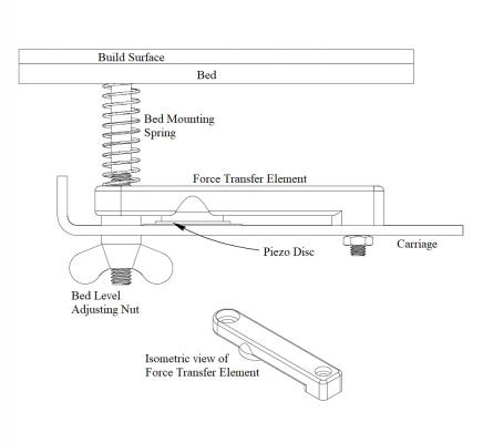
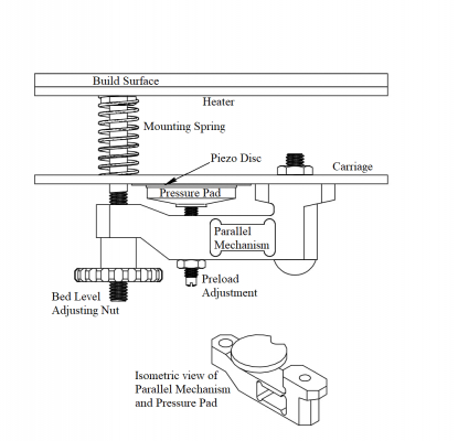
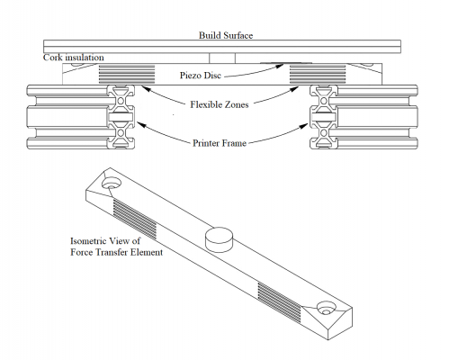
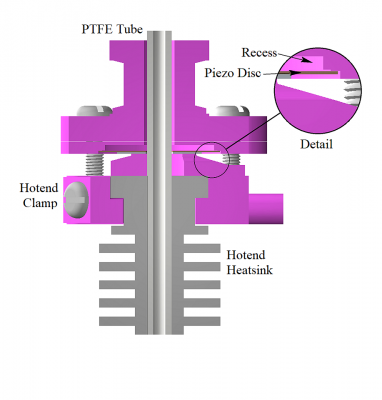
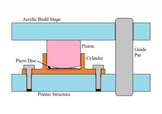
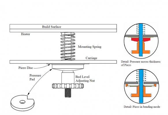
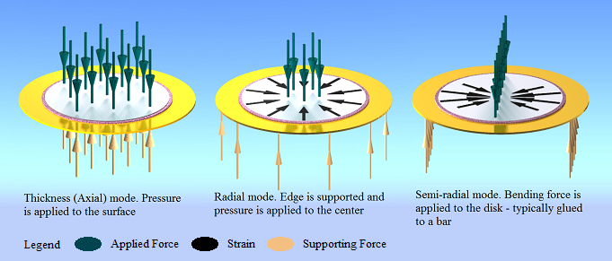
Piezoelectric discs are very effective at converting mechanical work into electrical charge. In practical terms this results in quite a large voltage being generated when a piezo disc is bent or put under pressure. With piezos giving so much more output than is needed it is possible to use them in a great many ways. Some of the principle modes used by contributors to the technology are illustrated in the drawings below
The first known use of piezos for nozzle contact detection was by elenhinan in 2015. His design transmitted the pressure of contact through a 3D printed bar which compressed the piezos between an expanded pad and the metalwork of the printer carriage.
In the hopes of improving on elenhinan's design I reversed the sense of the operation in that increasing nozzle contact pressure resulted in a reduction of the pressure on the piezo, The pressure pad was separated from the bar by a ball type pivot point so that the pressure was always applied evenly. In addition, the bar itself was redesigned to give quite free flexing while minimising compliance by incorporating a parallel linkage; this has resulted in a very low compliance with considerable sensitivity.
Moriquendi introduced us to the use of a piexo in the manner of a foil strain gauge, first using this on a effector based design and then on an underbed design. The underbed design is attractive in its simplicity and offers the option of getting a greater separation from the heated bed by mounting the piezo elements on the underside of the force transfer element.
DjDemonD introduced the use of a single drilled piezo in the print head, an arrangement which has proven reliable and accurate. As mentioned above two variants are now available through Precision Piezo [www.precisionpiezo.co.uk]
A very simple and elegant arrangement was designed by swoozle - my interpretation above based on his description and photograph.
A modification of my earlier design but without the parallel mechanism uses drilled piezos on the adjusting screws of the printer bed. Although I have not tried this in hot blood, I have found by experimentation that using a drilled piezo in the compression mode requires that the drilling does not result in any belling of the brass. If the brass is not dead flat there will be a double hump in the piezo output. An option with the piezo in bending works well but does introduce a very small amount of compliance,
I have realized at this point that the above is almost an invitation to a flood of tl:dnr* so I will break this summary into two or more parts.
Mike
*tl:dnr "too long: did not read" is normally in upper case but introduces a mad smiley TL NR
NR
Edited 1 time(s). Last edit at 06/02/2017 03:49AM by leadinglights.
Piezoelectric sensors now represent the best technology for setting nozzle height and testing the bed level on FDM 3D printers: Detecting nozzle contact with piezo discs has equal or better repeatability than any other method while having no inherent offest in X, Y or Z, the cost of a Piezo disc sensor with supporting electronics is less than other nozzle contact types such as FSR or accelerometer and is also less than deployable switch types. Proximity sensors suffer from sensitivity to build surface type and may be affected by humidity or ambient light which do not have any significant effect on piezo discs.
Piezoelectric discs are very effective at converting mechanical work into electrical charge. In practical terms this results in quite a large voltage being generated when a piezo disc is bent or put under pressure. With piezos giving so much more output than is needed it is possible to use them in a great many ways. Some of the principle modes used by contributors to the technology are illustrated in the drawings below
The first known use of piezos for nozzle contact detection was by elenhinan in 2015. His design transmitted the pressure of contact through a 3D printed bar which compressed the piezos between an expanded pad and the metalwork of the printer carriage.
In the hopes of improving on elenhinan's design I reversed the sense of the operation in that increasing nozzle contact pressure resulted in a reduction of the pressure on the piezo, The pressure pad was separated from the bar by a ball type pivot point so that the pressure was always applied evenly. In addition, the bar itself was redesigned to give quite free flexing while minimising compliance by incorporating a parallel linkage; this has resulted in a very low compliance with considerable sensitivity.
Moriquendi introduced us to the use of a piexo in the manner of a foil strain gauge, first using this on a effector based design and then on an underbed design. The underbed design is attractive in its simplicity and offers the option of getting a greater separation from the heated bed by mounting the piezo elements on the underside of the force transfer element.
DjDemonD introduced the use of a single drilled piezo in the print head, an arrangement which has proven reliable and accurate. As mentioned above two variants are now available through Precision Piezo [www.precisionpiezo.co.uk]
A very simple and elegant arrangement was designed by swoozle - my interpretation above based on his description and photograph.
A modification of my earlier design but without the parallel mechanism uses drilled piezos on the adjusting screws of the printer bed. Although I have not tried this in hot blood, I have found by experimentation that using a drilled piezo in the compression mode requires that the drilling does not result in any belling of the brass. If the brass is not dead flat there will be a double hump in the piezo output. An option with the piezo in bending works well but does introduce a very small amount of compliance,
I have realized at this point that the above is almost an invitation to a flood of tl:dnr* so I will break this summary into two or more parts.
Mike
*tl:dnr "too long: did not read" is normally in upper case but introduces a mad smiley TL
 NR
NREdited 1 time(s). Last edit at 06/02/2017 03:49AM by leadinglights.
|
Re: Piezoelectric disks for Z contact detect and bed levelling June 04, 2017 03:09PM |
Registered: 12 years ago Posts: 1,450 |
This is the second part of a summary of the previous posts in this thread. In this part I will try to concentrate on piezoelectric discs themselves rather than the geometry of their installation.
Everything below applies to the type of inexpensive disc which is found in a huge number of products as diverse as musical birthday cards and talking dolls all the way to sounders in the most mission critical aircraft instruments. This ubiquity comes from the reliability and low cost of these devices which in turn derives from their simplicity. From our point of view, their great virtue is found in their sensitivity to pressure or flexing which allows several volts to be generated by even a small mechanical force.
Piezo discs have been used in three ways which are all represented in the previous part of this summary.
Radial mode is closest to the manufacturer's design intent and gives the greatest output however other modes will still give sufficient sensitivity.
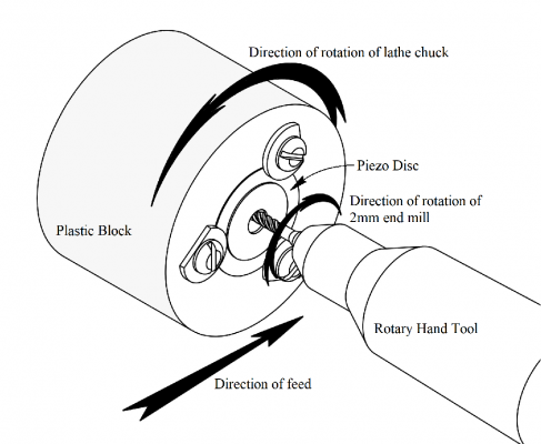
Piezoelectric discs are quite robust once installed but can be damaged by physically bending or heating; although with care they can be drilled or cut yet retain enough output to be useful. The piezoelectric material of which these disks is made is quite abrasive and will blunt even a tungsten carbide drill fairly quickly. A normal high carbon steel drill bit will drill the discs but will blunt after only 1 to 3 discs, however a method is shown below which has proven fairly economical on tools.
If a small pilot hole is drilled in the center of the disc, a tungsten carbide end mill held in a rotary too can be used to open out the hole. In the figure a lathe and a Proxxon rotary tool are used but is is possible to dispense with the lathe, the important point is that the tool is cutting sideways and not directly onto the abrasive ceramic.
Health and Safety Warning
Please note whatever method is used that that the ceramic contains lead and should be treated as a potentially hazardous material: Protect yourself and others from breathing in the dust generated by machining piezoelectric discs. The swarf and dust should be vacuumed up or picked up with a damp cloth or paper towel which should be disposed of.
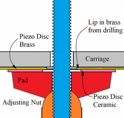
If discs are being drilled to be used in the thickness mode, with pressure directly applied between the surfaces, it is particularly important that the hole should be clean and without belling of the brass disc. In the the diagram below the brass disc has a lip which causes the disc not to seat fully against one of the surfaces causing the output from the disc to be unpredictable. Typically this will be a double hump on an oscilloscope trace of the disc output.
Piezoelectric discs do have to be protected from higher temperatures and from rapid changes in temperature. Locating underbed piezo discs at some distance from a heated bed or having a layer of insulation between the heated build stage and piezo discs is usually sufficient. Piezo discs in a hotend will typically be above the cooled part of the hotend and should not be a problem unless the printer runs in a heated enclosure.
The polarisation and sensitivity of piezoelectric discs varies depending on the source with some batches of "no-name" discs having sensitivities ranging over a 5 to 1 range and sometimes having random polarisation. Murata discs have consistent polarisation with a positive charge appearing on the red wire when pressure is applied to them. Sensitivity is also generally good on Murata discs although one batch purchased without leads did appear somewhat variable.
Mike
Edited 2 time(s). Last edit at 06/06/2017 04:23AM by leadinglights.
|
Re: Piezoelectric disks for Z contact detect and bed levelling June 08, 2017 09:23AM |
Registered: 7 years ago Posts: 61 |
Another piezo sensor board...looks like some level clamping diodes followed by a comparator giving an analogue output that can be adjusted for sensitivity... At £1.68 each I ordered two to find out
Piezo vibration sensor

Piezo vibration sensor
|
Re: Piezoelectric disks for Z contact detect and bed levelling June 08, 2017 02:18PM |
Registered: 12 years ago Posts: 1,450 |
Quote
dart16
Another piezo sensor board...looks like some level clamping diodes followed by a comparator giving an analogue output that can be adjusted for sensitivity... At £1.68 each I ordered two to find out
Piezo vibration sensor
Thanks dart16, I have just ordered two of these.
I am tying to put together a summary of all of the amplifiers and conditioning circuits that have appeared on this and related threads to see where we go next - I hope to put the summery on this thread in the next week or so
The biggest interest is in using a very cheap MCU to do some digital filtering - an idea that ECJ used in his version of a piezo hotend in South America. It is possible that it could be tuned very closely to the printer, possibly using soem sort of autotune such as used to tune the PID factors for the hotend heater.
Mike
|
Re: Piezoelectric disks for Z contact detect and bed levelling June 13, 2017 01:03PM |
Registered: 7 years ago Posts: 270 |
Here's piezzo vibration sensor by DFRobot:
[www.dfrobot.com]
Can be ordered directly or, maybe, through digikey:
[www.digikey.com]
Schematics:
[github.com]
[www.dfrobot.com]
Can be ordered directly or, maybe, through digikey:
[www.digikey.com]
Schematics:
[github.com]
|
Re: Piezoelectric disks for Z contact detect and bed levelling June 14, 2017 04:37AM |
Registered: 12 years ago Posts: 1,450 |
Hi newbob,
Thanks for the pointers but sadly the amplifier is not likely to be much use with piezo discs as sensors: The amplifier in the schematic has a gain of over 150 (set by R4 and R5) which is far too much - a gain of about 2 is about right with added sensitivity being got from the adjustment of the comparator. The frequency also starts to roll off far to early with sensitivity falling off above about 9Hz (set by R9 and C3) which is nearly the opposite of what we need for piezo discs.
I had thought of using the blade type of vibration sensor for detecting vibration/deceleration at the instant of nozzle contact but both shaking the numbers and trying it in the metal it turns out to be an almost spectacularly bad way of doing the job. I won't dismiss it entirely as some bright cookies at Seemecnc.com sell Rostock printers with accelerometer sensors but present indications are that they are no great shakes.
The piezo amplifier flagged up by dart16 a couple of posts ago may be a different thing entirely but I don't have a schematic to go by.
Mike
|
Re: Piezoelectric disks for Z contact detect and bed levelling June 14, 2017 09:09AM |
Registered: 6 years ago Posts: 1 |
|
Re: Piezoelectric disks for Z contact detect and bed levelling June 20, 2017 07:49AM |
Registered: 7 years ago Posts: 61 |
Slow boat delivery today.. Piezo vibration sensor boards arrived
As far as I can tell the schematic is as below..
The pot does seem to adjust the sensitivity sufficiently from quite a hard tap to just breathe on it! The piezo is 20mm diameter and the board is 20mm square. I am going to wire it up onto a printer and do some live testing....
Edited 1 time(s). Last edit at 06/20/2017 01:00PM by dart16.
|
Re: Piezoelectric disks for Z contact detect and bed levelling June 20, 2017 08:26AM |
Registered: 12 years ago Posts: 1,450 |
Hi Dart16,
Mine have caught the even-slower-boat and are not expected until next week???
Thanks for the schematic, looking at the circuit it looks as though it will do the job - as you said in your earlier posting it seem to be a comparator with some supporting passives. Low frequency will be set by the 1M resistor and should bi in the couple of Hz range depending on the capacitor of the piezo(s).
There is one small (and I stress small) problem in that there is no high frequency filtering. This may be problematic with printers with a lot of mechanical noise - typically not too bad on Delta printers. There may also be some susceptibility to electrical noise but easily overcome by having the amplifier within 100mm or so of the piezo. It is also slightly more important on this one to get the piezo the right way round.
Mike
|
Re: Piezoelectric disks for Z contact detect and bed levelling June 20, 2017 08:30AM |
Registered: 7 years ago Posts: 61 |
OK...so wired up and working. Turn trimmer down until the led lights up, then turn it back a smidge so the led goes out and there you have it..simple. Board cost is currently £1.68 with free delivery on the slow boat.
Piezo board triggering
Z homing
board trigger
I should add the piezo is about 1.25 Meters from the board as the cabling goes through 2 cable chains and I have not yet seen any noise problems, but it is early days still and the z carriage is slow moving
Edited 1 time(s). Last edit at 06/20/2017 08:33AM by dart16.
|
Re: Piezoelectric disks for Z contact detect and bed levelling June 20, 2017 08:41AM |
Registered: 12 years ago Posts: 1,450 |
|
Re: Piezoelectric disks for Z contact detect and bed levelling June 20, 2017 10:09AM |
Registered: 10 years ago Posts: 13 |
dart16, did you bore a hole through the Piezo or did you just attach it to your hot end mount?
I ask because I'm really hesitant to drill through those things. If the Piezo was oriented vertically and had a #8 nut glued to the ceramic face, it might provide enough mass to trigger the sensor properly...
tnx.
g.
I ask because I'm really hesitant to drill through those things. If the Piezo was oriented vertically and had a #8 nut glued to the ceramic face, it might provide enough mass to trigger the sensor properly...
tnx.
g.
|
Re: Piezoelectric disks for Z contact detect and bed levelling June 20, 2017 10:30AM |
Registered: 12 years ago Posts: 1,450 |
Hi geneb,
The piezos which have mainly been used have sensed the pressure transmitted from the nozzle contacting the bed, there is no need for a separate mass such as a #8 nut. I have done some experiments with using a piezo turned into an accelerometer with a ring around the outside but I found such poor sensitivity that I didn't persue it.
Drilling a hole in a piezo is fairly easy but takes a toll on drills, HSS drills may need sharpening after only one or two holes. Start with a pilot hole of about 1/16" (1.5mm) and then open it up to 4.5mm - there is a write up earlier in this thread.
Don't Breath the dust it is likely to be bad stuff.
Mike
|
Re: Piezoelectric disks for Z contact detect and bed levelling June 20, 2017 11:02AM |
Registered: 7 years ago Posts: 61 |
I didn't use the piezo that came with the board as I already had an assembled hotend with a drilled piezo sensor. The drilled piezo I had was actually a 27mm diameter, no-name element whereas the element supplied with the board was only 20mm so even with the missing material due to the hole there was still plenty of active surface with the drilled piezo.
Don't be too concerned about drilling the piezo, it is actually quite easy to do and not too critical with regards to hole position accuracy. I have just brutalised a 27mm dia piezo with a 4.5mm drill (shown alongside the 20mm supplied piezo). Obviously there are more refined ways to make the hole but it still works fine..
Don't be too concerned about drilling the piezo, it is actually quite easy to do and not too critical with regards to hole position accuracy. I have just brutalised a 27mm dia piezo with a 4.5mm drill (shown alongside the 20mm supplied piezo). Obviously there are more refined ways to make the hole but it still works fine..
|
Re: Piezoelectric disks for Z contact detect and bed levelling June 20, 2017 11:30AM |
Registered: 10 years ago Posts: 13 |
I wonder if a 1/4" "fish mouth" end mill would work... I've got lots of those.
The reason for the nut glued to the ceramic face is to give additional mass to it in order to deform the ceramic on impact when the piezo is oriented vertically. If it works, it would allow the use of the piezo system without having to make any special changes to the hot end mount. When I can, I'll get one of those boards ordered and test out the theory.
tnx.
g.
The reason for the nut glued to the ceramic face is to give additional mass to it in order to deform the ceramic on impact when the piezo is oriented vertically. If it works, it would allow the use of the piezo system without having to make any special changes to the hot end mount. When I can, I'll get one of those boards ordered and test out the theory.

tnx.
g.
|
Re: Piezoelectric disks for Z contact detect and bed levelling June 22, 2017 02:51PM |
Registered: 8 years ago Posts: 3,525 |
My method is to use a spur point wood drill bit 5mm (4.5mm if you can get them), download a drilling guide from my thingiverse listing (or make one its a 27/20mm disc with a 2-3mm hole in the middle to mark with a sharpie), then place the piezo brass side down onto an even circular blob of blue-tak. If needs be use a centre punch to start off in the dead centre, then using medium rpm and fairly high downwards pressure (assuming hand held drill - pillar drill would be better) you can go through in 10 seconds or so. Hold the piezo to aid in stopping it rotating and to feel if it starts to get hot. 60 degrees is where you'll want to take your fingers off due to the heat, you don't want to heat them up more than that.
You get a neat hole, not as neat as Leadinglight's method with the lathe but nearly as good (they certainly perform as well) and cheap and easy for all.
Simon Khoury
Co-founder of [www.precisionpiezo.co.uk] Accurate, repeatable, versatile Z-Probes
Published:Inventions
You get a neat hole, not as neat as Leadinglight's method with the lathe but nearly as good (they certainly perform as well) and cheap and easy for all.
Simon Khoury
Co-founder of [www.precisionpiezo.co.uk] Accurate, repeatable, versatile Z-Probes
Published:Inventions
|
Re: Piezoelectric disks for Z contact detect and bed levelling June 29, 2017 06:00AM |
Registered: 12 years ago Posts: 1,450 |
Just a quick update. I purchased a couple of the sensor boards that dart16 flagged up in the post below and have given them a bit of testing.
I am getting a bit better of a handle on how to recognize the signal of a nozzle contact and extract it from the background noise so I will spend some time in trying to resurrect old knowledge of how to program an MCU for a bit of signal processing - an idea inspired by ECJ and his version of the piezo Z probe.
Mike
- On my Delta printer they work very well indeed but this is a very quiet and vibration free machine.
- On my Cartesian printer they are not sufficiently reliable - this is because it is structurally an early Mk1 Mendel Prusa. The end of an X or Y movement is marked by a few hundred milliseconds of rattling, the only solution being to set the controller to insensitive and the nozzle contact to be fast (F500).
Quote
dart16
Another piezo sensor board...looks like some level clamping diodes followed by a comparator giving an analogue output that can be adjusted for sensitivity... At £1.68 each I ordered two to find out
Piezo vibration sensor
I am getting a bit better of a handle on how to recognize the signal of a nozzle contact and extract it from the background noise so I will spend some time in trying to resurrect old knowledge of how to program an MCU for a bit of signal processing - an idea inspired by ECJ and his version of the piezo Z probe.
Mike
|
Re: Piezoelectric disks for Z contact detect and bed levelling June 29, 2017 06:19AM |
Registered: 8 years ago Posts: 3,525 |
This is where RRF is now helping us immensely with M558 Rx switch where x is recovery time in seconds before probing dive takes place. 0.2sec seems to take care of this problem. Maybe put in a request with marlin, repetier etc to add this feature. Couple that with z max acceleration at 200mm/min and I'm probing without any other slowdowns /macros.
Edited 1 time(s). Last edit at 06/29/2017 06:21AM by DjDemonD.
Simon Khoury
Co-founder of [www.precisionpiezo.co.uk] Accurate, repeatable, versatile Z-Probes
Published:Inventions
Edited 1 time(s). Last edit at 06/29/2017 06:21AM by DjDemonD.
Simon Khoury
Co-founder of [www.precisionpiezo.co.uk] Accurate, repeatable, versatile Z-Probes
Published:Inventions
|
Re: Piezoelectric disks for Z contact detect and bed levelling June 29, 2017 07:16AM |
Registered: 10 years ago Posts: 14,672 |
Quote
DjDemonD
This is where RRF is now helping us immensely with M558 Rx switch where x is recovery time in seconds before probing dive takes place. 0.2sec seems to take care of this problem. Maybe put in a request with marlin, repetier etc to add this feature. Couple that with z max acceleration at 200mm/min and I'm probing without any other slowdowns /macros.
I plan to limit the Z acceleration and the start of Z probe moves in the next release of RRF. I'm not sure it needs to be configurable. I am assuming that we want to be able to achieve a Z probing speed of 20mm/sec in no more than 1mm of movement. Based on those figures, your acceleration limit of 200mm/sec^2 looks about right.
Edited 1 time(s). Last edit at 06/29/2017 07:17AM by dc42.
Large delta printer [miscsolutions.wordpress.com], E3D tool changer, Robotdigg SCARA printer, Crane Quad and Ormerod
Disclosure: I design Duet electronics and work on RepRapFirmware, [duet3d.com].
|
Re: Piezoelectric disks for Z contact detect and bed levelling June 29, 2017 07:45AM |
Registered: 8 years ago Posts: 3,525 |
Well I advise customers to use between 4-7 mm/s probing speed for our sensor. The 200mm/s2 acceleration is just a reasonable value for general printing, which is also low enough not to upset the sensor with a mechanically noisy machine.
Edited 2 time(s). Last edit at 06/29/2017 08:41AM by DjDemonD.
Simon Khoury
Co-founder of [www.precisionpiezo.co.uk] Accurate, repeatable, versatile Z-Probes
Published:Inventions
Edited 2 time(s). Last edit at 06/29/2017 08:41AM by DjDemonD.
Simon Khoury
Co-founder of [www.precisionpiezo.co.uk] Accurate, repeatable, versatile Z-Probes
Published:Inventions
Sorry, only registered users may post in this forum.
