PCB by EDM
Posted by Andrey_SSh
|
PCB by EDM April 15, 2016 12:26AM |
Registered: 8 years ago Posts: 29 |
Hello.
As you can see my english is not too good. So I'm sorry. I will be happy if my messages will be corrected by anybody.
I want to discuss the printed circuit board manufacturing technology, using the electric discharge machine.
1.
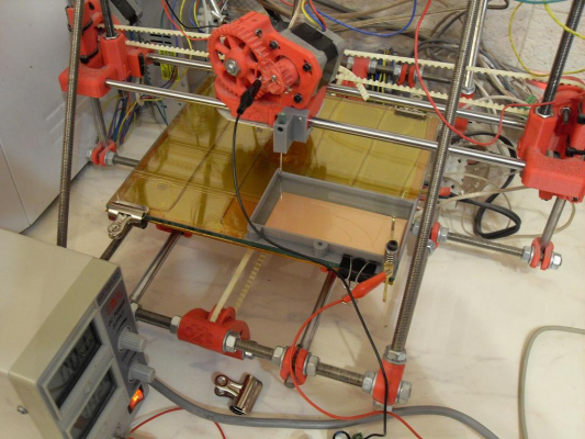
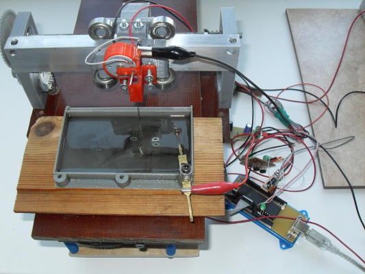
RepRap Mendel equipped with the oil tray and electrode, mounted on the extruder gear,
Power suplay - 18 V, short circuit protected.
2.
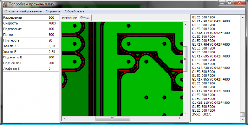
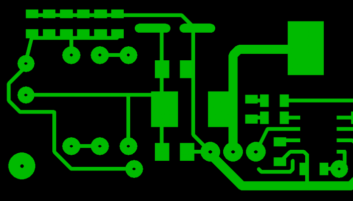
Special program for G-code prepearing was developed (resounding word). It take a bitmap file as input.
3.
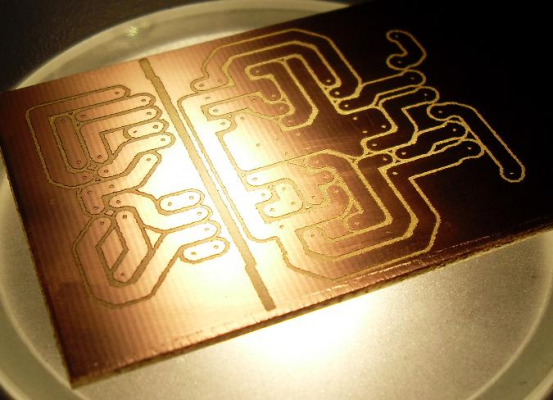
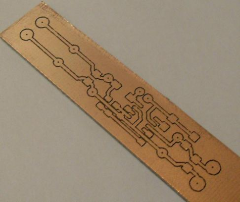
As a result - PCB for stepper motor driver.
4.
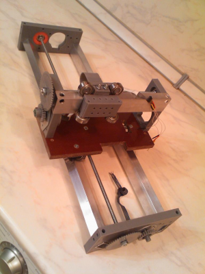
Belt based 3d-printer has insufficient precision, so I buid screw based 2-dimensional machine. This is old photo of mechanical part without spark-head. This device is very slow.
5.
About 8 hours needed for this PCB.
6.
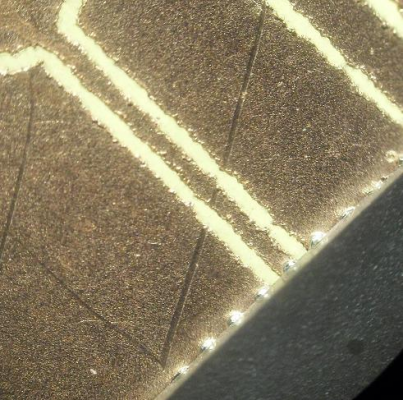
Trace 0.2 mm width for QFN available.
Advantages:
- one step technology (no cleaning, no other pre and post processing).
- no chemicals
- RepRap compatible
- cheap and available materials (copper wire and sunflower-seed oil)
- no acoustic noise
Disadvantages
- jugged edges reduces electrical strength of the gap
- unregulated gap width (or too many time for gap broadening)
- electromagnetic noise
Edited 3 time(s). Last edit at 04/15/2016 01:15AM by Andrey_SSh.
|
Re: PCB by EDM April 15, 2016 02:38AM |
Admin Registered: 13 years ago Posts: 7,000 |
|
Re: PCB by EDM April 15, 2016 02:57AM |
Registered: 8 years ago Posts: 29 |
|
Re: PCB by EDM April 15, 2016 03:14AM |
Admin Registered: 16 years ago Posts: 13,886 |
... the greatest drawback with EDM is the slow speed.
I'm DIY-manufacturing PCB's with laser-engraving black painted boards and etching the engraved lines in maybe 10 minutes - here's a related thread:
[forums.reprap.org]
If building time is no problem, then it's a good etch-free alternative though, similar to engraving with a mill-bit ...
Viktor
--------
Aufruf zum Projekt "Müll-freie Meere" - [reprap.org] -- Deutsche Facebook-Gruppe - [www.facebook.com]
Call for the project "garbage-free seas" - [reprap.org]
|
Re: PCB by EDM April 15, 2016 01:23PM |
Admin Registered: 13 years ago Posts: 730 |
This is great work Andrey_SSh, thank you for sharing! 
We have talked about EDM in other threads on the forum. You might be interested in this thread: DIY EDM
Can you show us how the driving circuit works?
What is the voltage and capacitance you are using?
How is the tooltip Z position controlled? Is this with the build platform Z motors or with a modified extruder?
When the tooltip is positioned at X and Y, does it just go down and up once in Z? Or does it go down and up in Z many times before moving to the next (X,Y)? If it goes down and up many times for each (X,Y) how does the system determine when to go to the next (X,Y)?
Could you use this to cut sheet metal?
|
Re: PCB by EDM April 16, 2016 01:56AM |
Admin Registered: 13 years ago Posts: 7,000 |
|
Re: PCB by EDM April 16, 2016 05:17AM |
Registered: 8 years ago Posts: 29 |
Thanks.
Capacitor charger.
Needs powerful bipolar transistor (TO-92MOD or more) for charging and signal FET (SOT-23 enough) for charging interruption during short-circuit. Optocouple used for spark detection.
Electrode operates by small DC brush motor. Motor controlled with simple H-brige driver by main controller (ATMega32). Syringe nidle used for electrode direction.
All PCBs (8 total) on the photo manufactured with this technology. 5 of them by slowbot itself.
Electrode go up and down while copper layer not burned. If last up/down cycle went off without spark, then go to next point.
Z-position controlled by wooden plank under the tray.
> to cut sheet metal
Yes, but too slow for practical purposes.
Acceptable speed achieved only with 200 um Al foil. May be usable for solder paste stancils.
|
Re: PCB by EDM April 29, 2016 07:22AM |
Registered: 8 years ago Posts: 29 |
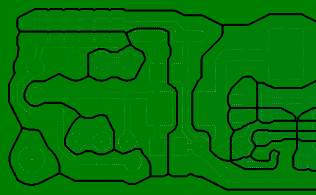
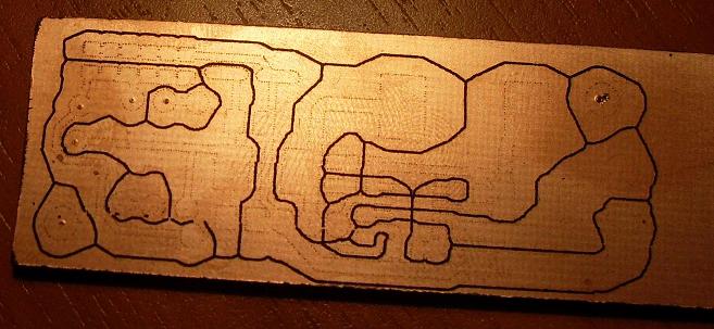
New algorithm of pcb processing.
Source:
Processed:
Manufactured:
This metod needs less head movements, so it is faster.
Additionally:
- less trace resistance
- less heat resistance
- more stray capacitance.
Source:
Processed:
Manufactured:
This metod needs less head movements, so it is faster.
Additionally:
- less trace resistance
- less heat resistance
- more stray capacitance.
|
Re: PCB by EDM April 29, 2016 08:45AM |
Registered: 13 years ago Posts: 7,616 |
Yes, Voronoi paths are quite usable, I use them all the time.
Your manufacturing method appears to still have some flaws, I see a number of bridges. I think you have to sort paths by distance from the electrode connected to the stock. Start with paths on the far end, make those close to the electrode later. This way you have always a good electrical connection to the electrode.
Your manufacturing method appears to still have some flaws, I see a number of bridges. I think you have to sort paths by distance from the electrode connected to the stock. Start with paths on the far end, make those close to the electrode later. This way you have always a good electrical connection to the electrode.
| Generation 7 Electronics | Teacup Firmware | RepRap DIY |
|
Re: PCB by EDM May 01, 2016 04:39AM |
Registered: 8 years ago Posts: 29 |
For PCB or other purposes?Quote
Traumflug
Yes, Voronoi paths are quite usable, I use them all the time.
Briges appeared due to head fault. Electrode-wire was broken during process (metall fatigue). After refit process was restored, but G-code position was choosen erroneously.
Tiny unvisible briges also appers sometimes.
>Start with paths on the far
No. This is the raster machine. Vector mode available, but not usable due to backslashes.
Voronoi algoritm is raster based also.
PS.
Message "this forum is moderated and your post will be hide ..." appeared.
Rules do not contain such points. And it is strange for 8-th post.
Obscurities.
PPS
Posted.
Two computers logged on simultaneously, may cause such behavior.
Edited 1 time(s). Last edit at 05/01/2016 04:42AM by Andrey_SSh.
|
Re: PCB by EDM May 01, 2016 06:52AM |
Admin Registered: 16 years ago Posts: 13,886 |
... I've deleted your first "to be moderated" post, as the second was the same with updates.
This sometimes occures with login-issues ... I have regularly to approve some messages of new members
Viktor
--------
Aufruf zum Projekt "Müll-freie Meere" - [reprap.org] -- Deutsche Facebook-Gruppe - [www.facebook.com]
Call for the project "garbage-free seas" - [reprap.org]
This sometimes occures with login-issues ... I have regularly to approve some messages of new members

Viktor
--------
Aufruf zum Projekt "Müll-freie Meere" - [reprap.org] -- Deutsche Facebook-Gruppe - [www.facebook.com]
Call for the project "garbage-free seas" - [reprap.org]
|
Re: PCB by EDM May 22, 2016 11:08PM |
Registered: 8 years ago Posts: 29 |
Some experiments was conducted for voltage and capacity optimization.
Conclusions:
1. Voltage more then 100 V leads to smooth edges. Shape of the electric field around the electrode is smoother then shape of electrode itself.
2. 100 V sparks are noisy as tiny petards.
3. For 35 um copper, spark energy must be about 15 mJ (independently of voltage). More energy - jugged edges. Less energy - low speed.
4. With 100 V and vegetable oil spark gap is too narrow for mechanical control.
Sorry, only registered users may post in this forum.
