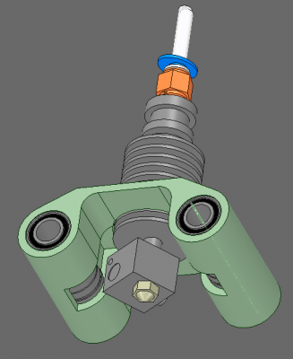
Started designing an efficient Horizontal XCarriage. Looking for your experience and input
Posted by realthor
|
Started designing an efficient Horizontal XCarriage. Looking for your experience and input May 27, 2016 03:10AM |
Registered: 9 years ago Posts: 1,035 |
Hi guys, I have researched into this before without too much success so I am coming back to it.
As much of a fan of the vertical carriages as I am, I came to believe that a horizontal rods X carriage can be made more balanced and symmetric than a vertical one so that rotation around the Y carriages will not affect it much because the nozzle, being in between rods and at about the same level with them, becomes the center of a circle and the center will not rotate if the diameter of the circle rotates.
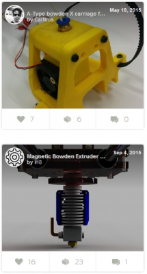
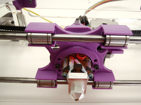
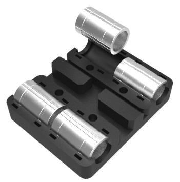
So I am researching for a design that allows such a positioning of the hotend/nozzle without being too bulky. I have found on thingiverse two such examples just one below the other so that I could snap a picture that would describe exactly what I am talking about:
I believe the upper is a better design choice as it keeps the nozzle very close to the center of the horizontal rods.
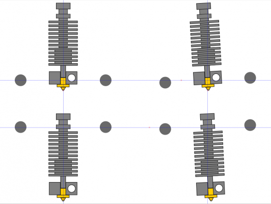
Here below you can see exactly what I am talking about:
Edited 3 time(s). Last edit at 05/28/2016 11:19AM by realthor.
RepRap Lander concept on Concept Forge
RepRap Lander concept on RepRap Forums
My Things, mostly experimental stuff
|
Re: Looking for a Horizontal XCarriage that has the nozzle just below the rods May 27, 2016 05:36AM |
Registered: 8 years ago Posts: 776 |
go through the possible combinations of tolerances, imagine there is +/-0.5mm tolerance on both rods. + on both rods will lift the carriage by 0.5mm, but you have gravity to counteract that. - on both rods will put the carriage down by 0.5mm, but again you have gravity to counteract that.
when you get only *one* rod going up by 0.5mm and the other stays where it is the head in the centre-arrangement *raises* by HALF that amount - 0.25mm. the angle is so small (sin(1degree or so)) that the amount it moves sideways under these circumstances is negligeable.
however with the lowered-carriage design even the smallest rotation means you get multiplied *sideways* movement as well as vertical.
you do have to take into account that the hotend has to be below the rods slightly but the further up you can get it the better.
|
Looking for an efficient Horizontal XCarriage May 27, 2016 06:01AM |
Registered: 9 years ago Posts: 1,035 |
The Closed bearings don't help with getting the nozzle as close to the rods, diameter as you have to add the difference but the open style bearings (LM8UUOP ex) can help a lot with bringing the nozzle upwards as much as possible. But I am not sure about the tolerances difference between the closed and opened bearings. How much worse are the open bearings with the forces involved with 3d printing (speed, acceleration, jerk, etc) than the closed bearings?
Edited 2 time(s). Last edit at 05/27/2016 06:06PM by realthor.
RepRap Lander concept on Concept Forge
RepRap Lander concept on RepRap Forums
My Things, mostly experimental stuff
Edited 2 time(s). Last edit at 05/27/2016 06:06PM by realthor.
RepRap Lander concept on Concept Forge
RepRap Lander concept on RepRap Forums
My Things, mostly experimental stuff
|
Re: Looking for an efficient Horizontal XCarriage May 27, 2016 05:50PM |
Registered: 9 years ago Posts: 1,035 |
I was wrong in my reasoning above: the center of rotation is entirely dependent on the YCarriage and has nothing to do with where the XRods are situated, because rotation in YCarriage bearings will influence the rotation of the XCarriage thus the movement of the nozzle from its designated position. SO it's actually a little bit easier to position the nozzle at the same height with the YRods axis plane if the XRods are above the YRods plane, like in the image below:
So actually the YCarriages design is critical in this aspect and the X carriage can easily be very effective even if it is in the configuration presented in the below image in the screenshot of the first post.
I am actually relived to have been mistaken.
Of course then it is pretty important that the weight of the X carriage is VERY close to the XRods plane, otherwise one would get rotation/twisting of the XRods when accelerating or decelerating the printhead and that is easier achievable with the image above that I dismissed in the first place (supposing the XRods are so high on the YCarriage that the nozzle is at the center of the YRods - which I am sure is not the case but that would be the ideal configuration).
Edited 4 time(s). Last edit at 05/27/2016 06:05PM by realthor.
RepRap Lander concept on Concept Forge
RepRap Lander concept on RepRap Forums
My Things, mostly experimental stuff
|
Re: Looking for an efficient moving XY setup May 27, 2016 06:44PM |
Registered: 9 years ago Posts: 1,035 |
Sorry for not waiting for answers from the community but I am trying to define how an ideal/efficient moving XY setup for horizontal rods would look like.
So far I have defined that:
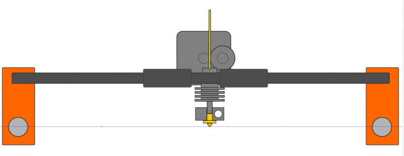
1) nozzle must be at the same height with YRods centers (to prevent positional errors due to slack/rotation of the YCarriages bearings)
2) the center of gravity of the XCarriage must be right in between the XRods (to prevent twist in the XRods due to a too high payload -ex extruder motor is 50mm above the XRods)
3) the XRods should ideally be as close to the Y rods as possible (to prevent skewing of the assembly on fast X movements -accelerations/stops-)
So far this is a sketch of how I see a good moving XY setup for horizontal XRods:
RepRap Lander concept on Concept Forge
RepRap Lander concept on RepRap Forums
My Things, mostly experimental stuff
|
Re: Looking for an efficient Horizontal XCarriage May 28, 2016 01:04AM |
Registered: 10 years ago Posts: 1,401 |
Unless you are planning on using thick rods and metal Y carriages, your movement in the X axis will swing your Y carriages, besides you are not accounting for the drive shaft that will move your Y carriages been so long will flex and create torque issues (be sure to use correct size to prevent it).
Best desig is X and Y axis at the plane.
Best desig is X and Y axis at the plane.
|
Re: Looking for an efficient Horizontal XCarriage May 28, 2016 03:40AM |
Registered: 9 years ago Posts: 1,035 |
Quote
ggherbaz
Unless you are planning on using thick rods and metal Y carriages, your movement in the X axis will swing your Y carriages
Yes I am aware that in the sketch above the XRods insertion on the YCarriages should be VERY sturdy to prevent skewing of the XY assembly and that it asks for some metal in the YCarriage.
[/quote]Quote
ggherbaz
Best desig is X and Y axis at the plane.
My 3) statement above says that best is to have XRods as close as possible to the YRods plane, which would be in the ideal situation the same plane. But then the Hotend must be so short as to have the moving mass of the direct extruder rigt on the XRods while having the nozzle at the YRods plane. Walking on VERY thin ice

Quote
ggherbaz
besides you are not accounting for the drive shaft that will move your Y carriages been so long will flex and create torque issues (be sure to use correct size to prevent it).
I am sure I've missed a lot actually I know of a few more I've missed in order to have a few issues solved at a time. I am especially talking about a coreXY configuration here so you must be referring to the belts that have to make a 90 deg turn to the XCarriage and, because the XCarriage is higher, the belt but be at that level forcing the YCarriage to rotate upon itself, right?
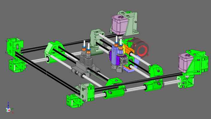
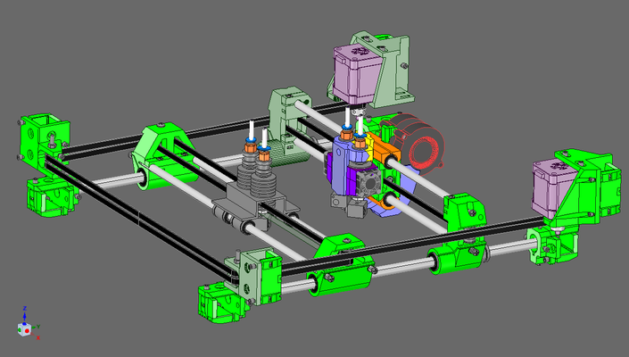
This is how my CoreXY stage concept looks like, with both horizontal XCarriage (not yet designed, hence this thread) and vertical XCarriage arrangement so some things are unavoidable (like the higher insertion of the XY belts on the YCarriages)...
Edited 4 time(s). Last edit at 05/28/2016 04:34AM by realthor.
RepRap Lander concept on Concept Forge
RepRap Lander concept on RepRap Forums
My Things, mostly experimental stuff
|
Re: Started designing an efficient Horizontal XCarriage. Looking for your experience and input May 28, 2016 12:10PM |
Registered: 10 years ago Posts: 1,401 |
|
Re: Started designing an efficient Horizontal XCarriage. Looking for your experience and input May 28, 2016 02:05PM |
Registered: 9 years ago Posts: 1,035 |
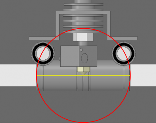
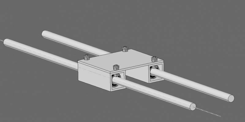
I am wondering if LME8UU (16mm diam LM8UU linear bearing) inserted in 20x20x2mm ALU square tube would be capable of performing under the loads of typical 3d printing. I am thinking of the following:
but the bearing touches the ALU in 4 lines along the tube and It might pretty quickly wear out the aluminum walls and get play in there. So my question is: is plastic better for holding the bearings than the solution above?
RepRap Lander concept on Concept Forge
RepRap Lander concept on RepRap Forums
My Things, mostly experimental stuff
|
Re: Started designing an efficient Horizontal XCarriage. Looking for your experience and input May 28, 2016 02:29PM |
Registered: 10 years ago Posts: 1,401 |
|
Re: Started designing an efficient Horizontal XCarriage. Looking for your experience and input May 28, 2016 03:18PM |
Registered: 9 years ago Posts: 1,035 |
Yes of course I know about that. This was an exercise to re-use some of the left-out tube from the construction of the frame and bed support

RepRap Lander concept on Concept Forge
RepRap Lander concept on RepRap Forums
My Things, mostly experimental stuff
|
Re: Looking for an efficient Horizontal XCarriage May 28, 2016 05:06PM |
Registered: 8 years ago Posts: 776 |
Quote
realthor
I am sure I've missed a lot actually I know of a few more I've missed in order to have a few issues solved at a time. I am especially talking about a coreXY configuration here so you must be referring to the belts that have to make a 90 deg turn to the XCarriage and, because the XCarriage is higher, the belt but be at that level forcing the YCarriage to rotate upon itself, right?
realthor: ambiguity-alert, ambiguity-alert! wark, wark, possibility for confusion! you haven't stated clearly the axis about which you are expecting the YCarriage to rotate. it can be X, or Y, or Z, or a combination of those, or, if you have some really weird design, the axis would have to be expressed as a 3x3 matrix (!!!) to make it absolutely clear (google it, if you're not sure why rotation in 3D is expressed as a 3x3 matrix).
also, the words say "the belt BUT be" which i can only think you must be using auto-complete or auto-suggestion or something (which you REALLY should switch off on a technical forum as it could substitute totally the wrong word). can you correct this so the words make a syntactically-correct sentence?
|
Re: Started designing an efficient Horizontal XCarriage. Looking for your experience and input May 28, 2016 05:15PM |
Registered: 8 years ago Posts: 776 |
ggherbaz, realthor: apologies but nobody can tell what you are talking about because we cannot see that product.
that link does not take me (or anyone else) to a product page, it takes me to a *login* page which demands my email address and a password. which, because it is a china-run company, i refuse to provide them with my email address (because they might sell it and i will receive even more spam). but, even more than that, the product may expire, be removed, or, even worse, may have a *different* product (similar or quotes equivalent quotes) put in its place. this is *VERY* common in china, and as aliexpress is a china web site it is extremely likely that the part will be substituted, making this discussion MISLEADING.
could i possibly ask you, for the future convenience of anyone reading this forum in the next 2 decades who may encounter this thread, to include a link or an image of the actual product, and to consider also to include a description or the technical specification of the part being discussed? a part number, especially if it is an industry-standard, would be even better.
that way, anyone coming to this forum, looking for good advice, will have exactly the information that they need, and will not be misled.
|
Re: Started designing an efficient Horizontal XCarriage. Looking for your experience and input May 28, 2016 05:21PM |
Registered: 9 years ago Posts: 1,035 |
@lkcl:
1) For the life of me I can't reverse-engineer what I meant there... but it was basically related to my belts being above the Y rods and also above the X rods, thus, because of this height, is pulling to rotate the YCarriages during functioning;
2) I don't understand the matrix thing but then again is past midnight here and I am quite tired.
3) ggherbaz's suggestion is of course the usual linear bearing housing that can be bought for less money from China (SC<#>[L]UU).
RepRap Lander concept on Concept Forge
RepRap Lander concept on RepRap Forums
My Things, mostly experimental stuff
|
Re: Looking for an efficient Horizontal XCarriage May 28, 2016 05:38PM |
Registered: 8 years ago Posts: 776 |
right. is that an offset belt arrangement, with every part of one belt being at the exact same Z-height as all other parts of that belt?
because if so you can do this:
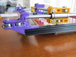
look very carefully at that carriage (orange). you see how the top and bottom bearings are offset ? (i am not talking about the Z-offset, i am referring to the fact that the two bearings do not share one single bolt) so you see here have to have two bolts?
what that means is that the bottom belt *and* the top belt turn and come in on *EXACTLY* the same line when viewed from above. and oh look what a coincidence (not really...) that line happens to be *EXACTLY* on the centre of gravity of the hotend. and oh look what a coincidence (not really) each belt goes round and comes in at exactly the same line on the other side as well.
this basically eliminates the kind of rotation about the Z axis that is normally inherent in most corexy designs during acceleration, as both belts are guaranteed in BOTH x AND y directions to ONLY pull on the centre of gravity of the carriage. a "normal" corexy design - i say normal but i actually mean a "flawed design aspect inherent in all other corexy 3d printers which nobody seems to have noticed or raised before" - will always have the carriage be twisted ever so slightly under acceleration, resulting in side-loading of the bearings if nothing else. it will depend on how good the quality of those bearings are as to whether people will notice this flaw in the actual results: the higher the quality of the linear bearings, the less likely they are to notice the effects of this "normal" design flaw.
so for the sake of two extra bolts, realthor, you could eliminate belt-induced rotation about the Z axis, with no design compromise, other additional trade-off, or loss of precision.
.... *if* that is what you were referring to.... i don't know, because your sentence was ambiguous. i could not tell if you were talking about belts causing rotation about the X axis, or if you were talking about the Y axis, or the Z axis, or any combination of all three... because you didn't say which.
Edited 1 time(s). Last edit at 05/28/2016 06:21PM by lkcl.
|
Re: Started designing an efficient Horizontal XCarriage. Looking for your experience and input May 28, 2016 05:53PM |
Registered: 9 years ago Posts: 1,035 |
Ok, I know what you mean about the ever so slight rotation about the Z axis. That can easily be done.
2) I was referring to the rotation of the YCarriage on the X axis as the belts are offset from the YRods center and tend to pull on the carriage from above, trying to take it down (like pulling a tree to take it down)... That is what is being resolved by having the nozzle right at that exact center of rotation.
3) the rotation about each Y axis is a result of the XRods plane distance from the YRods plane, that's why I am trying to have them (the planes) as close as possible to each other. But that introduces another issue: the heater block sits just next to the rods, where there should be the housing of the bearings and the XCarriage itself whic, being plastic, is prone to deformation due to the heat... hence my bearings-inside-leftover-tubes idea above ....
Edit: I am starting from here:
I'll see where I get.
Edited 1 time(s). Last edit at 05/28/2016 05:57PM by realthor.
RepRap Lander concept on Concept Forge
RepRap Lander concept on RepRap Forums
My Things, mostly experimental stuff
|
Re: Started designing an efficient Horizontal XCarriage. Looking for your experience and input May 28, 2016 06:13PM |
Registered: 8 years ago Posts: 776 |
realthor, get some rest! read this when you're rested, okay! if tempted to reply, please wait until tomorrow! sleep is gooood 
ok, so let's work it out by a process of elimination. if you are referring to all belts, then you are *probably* not talking about the solution i referred to above, which eliminates rotation about the Z-axis.
therefore you are most likely talking about rotation around the..... let me think.... x rods are along what we call "x-axis" in the 3d world, and y rods are along what we call the "y axis". because both belts are offset in Z, then during acceleration the force difference (because the belt on the accelerating side will stretch under load, the belt on the opposite side will be slacker, this results in a change in the load on the carriage....) will, yes, cause a rotational load about the *Y* axis. note i said "Y axis", i did *not* say "Y rod" there! again, if you don't fully understand the phrase, *please google it*. the question you should type into google is, "what does rotation about the y axis mean?".
so, if that's what you mean (please check it, so that we know we are on the same page) - maybe even draw a diagram (to save me typing, as the tendons in my forearms really hurt now), then we (and other people if they want to help) can work through some solutions and analyse them.
i'm saving typing (and my time) - i have bad RSI again and i don't want to duplicate pages of mathematical explanation that you can find with a google search "3D matrix rotation" and they will do a much better job than me anyway. let me check that... yep. every single one of the first 7 hits for that set of keywords is relevant, there may be many more. please review the ones that you find to be most appropriate, there is even a youtube video one which really surprises me.
ahh ok, now i know what you're referring to. the "linear bearing platform" things. yeah they're great, but on the same rod you usually need 2, separated as far apart as your design will allow, to reduce rotation due to machining tolerances (of a single bearing). but there is another reason why they are preferred, as Alex_F found out when he used 2 LM8UUs in the Fusebox: plastic housings do *not* line up the LM8UU bearings properly, so each bearing ends up being slightly off its intended operating line (parallel to the direction it moves in!!!!! duh!!!!) resulting in stress on the rod (and the bearings). eventually something breaks (or wears out). you can hear something's wrong because there is a horrible sound from the printer, even when it is new.
Alex_F fixed this by converting to LM8LUU bearings for the Fusebox carriage, which... well, i honestly don't have enough experience here to say whether 2 SC8UU bearings on a metal plate would be better or worse than one LM8LUU.
anyway too early, we have to be clear about what it is you are trying to tackle, first.
Edited 1 time(s). Last edit at 05/28/2016 06:13PM by lkcl.

Quote
realthor
@lkcl:
1) For the life of me I can't reverse-engineer what I meant there... but it was basically related to my belts being above the Y rods and also above the X rods, thus, because of this height, is pulling to rotate the YCarriages during functioning;
ok, so let's work it out by a process of elimination. if you are referring to all belts, then you are *probably* not talking about the solution i referred to above, which eliminates rotation about the Z-axis.
therefore you are most likely talking about rotation around the..... let me think.... x rods are along what we call "x-axis" in the 3d world, and y rods are along what we call the "y axis". because both belts are offset in Z, then during acceleration the force difference (because the belt on the accelerating side will stretch under load, the belt on the opposite side will be slacker, this results in a change in the load on the carriage....) will, yes, cause a rotational load about the *Y* axis. note i said "Y axis", i did *not* say "Y rod" there! again, if you don't fully understand the phrase, *please google it*. the question you should type into google is, "what does rotation about the y axis mean?".
so, if that's what you mean (please check it, so that we know we are on the same page) - maybe even draw a diagram (to save me typing, as the tendons in my forearms really hurt now), then we (and other people if they want to help) can work through some solutions and analyse them.
Quote
2) I don't understand the matrix thing but then again is past midnight here and I am quite tired.
i'm saving typing (and my time) - i have bad RSI again and i don't want to duplicate pages of mathematical explanation that you can find with a google search "3D matrix rotation" and they will do a much better job than me anyway. let me check that... yep. every single one of the first 7 hits for that set of keywords is relevant, there may be many more. please review the ones that you find to be most appropriate, there is even a youtube video one which really surprises me.
Quote
3) ggherbaz's suggestion is of course the usual linear bearing housing that can be bought for less money from China (SC<#>[L]UU).
ahh ok, now i know what you're referring to. the "linear bearing platform" things. yeah they're great, but on the same rod you usually need 2, separated as far apart as your design will allow, to reduce rotation due to machining tolerances (of a single bearing). but there is another reason why they are preferred, as Alex_F found out when he used 2 LM8UUs in the Fusebox: plastic housings do *not* line up the LM8UU bearings properly, so each bearing ends up being slightly off its intended operating line (parallel to the direction it moves in!!!!! duh!!!!) resulting in stress on the rod (and the bearings). eventually something breaks (or wears out). you can hear something's wrong because there is a horrible sound from the printer, even when it is new.
Alex_F fixed this by converting to LM8LUU bearings for the Fusebox carriage, which... well, i honestly don't have enough experience here to say whether 2 SC8UU bearings on a metal plate would be better or worse than one LM8LUU.
anyway too early, we have to be clear about what it is you are trying to tackle, first.
Edited 1 time(s). Last edit at 05/28/2016 06:13PM by lkcl.
|
Re: Started designing an efficient Horizontal XCarriage. Looking for your experience and input May 28, 2016 06:20PM |
Registered: 8 years ago Posts: 776 |
Quote
realthor
Ok, I know what you mean about the ever so slight rotation about the Z axis. That can easily be done.
cool.
Quote
2) I was referring to the rotation of the YCarriage on the X axis as the belts are offset from the YRods center and tend to pull on the carriage from above, trying to take it down (like pulling a tree to take it down)... That is what is being resolved by having the nozzle right at that exact center of rotation.
awesome. ok so we're now clear, i like the tree analogy, but again, it doesn't tell me where *you* are standing, relative to the tree. what i was trying to establish was - to again extend the analogy - a frame of reference to understand, relative to e.g. say... "magnetic north", where the person doing the pulling is standing. if you had said, "like standing *exactly to the north of a tree* and pulling it to take it down" *then* we would have all the information needed, do you see the difference?
ok, very late here, let me think about it overnight, and reply tomorrow on (3) ok?
|
Re: Started designing an efficient Horizontal XCarriage. Looking for your experience and input May 29, 2016 04:25AM |
Registered: 8 years ago Posts: 776 |
Quote
realthor
3) the rotation about each Y axis is a result of the XRods plane distance from the YRods plane, that's why I am trying to have them (the planes) as close as possible to each other. But that introduces another issue: the heater block sits just next to the rods, where there should be the housing of the bearings and the XCarriage itself whic, being plastic, is prone to deformation due to the heat... hence my bearings-inside-leftover-tubes idea above ....
yeah makes sense. oh remember to make enough room for fans!
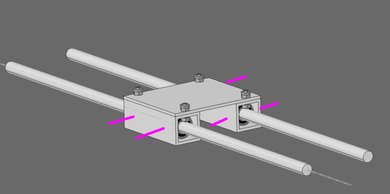
so, what occurred to me was, you want a way to take up the slack in the bearings. if the rods are a fixed width apart, you can't do that. or, if the bearings are fixed, you can't do that. so, why not add some sort of screw adjustments to be able to seat the bearings at variable distances? btw this would only really work if you had two LM8UU bearings inside each of those metal tubes, okay?
so you have 8 screws, 2 each side of each of the 4 bearings. you use those screws as pivot-points (so you do them up quite tight so that the bearings don't move about, but use them to set the position)
hmmm... no, i don't like this idea. it's too fiddly.
what would be better would be to have:
- 1 screw per bearing on the outside, *offset* (i.e. slightly higher than the centre-line of the bearing) which when tightened forces the bearing into a corner against 2 walls. this locks it solid and stops it moving inside the square tube
- slots instead of holes for those 4 bolts holding the square tube onto the plate. you can then adjust the position of the tubes to make up any machine-tolerance slack in the bearings.
what you will have to watch out for is, wear in the bearings on one side (the one that's taut). you would need to set up a maintenance cycle which rotates the bearings periodically, so as to get even wear. also you'd need those grippy-washers to make absolutely sure that the nuts and bolts holding the square tube to the plate do not move.
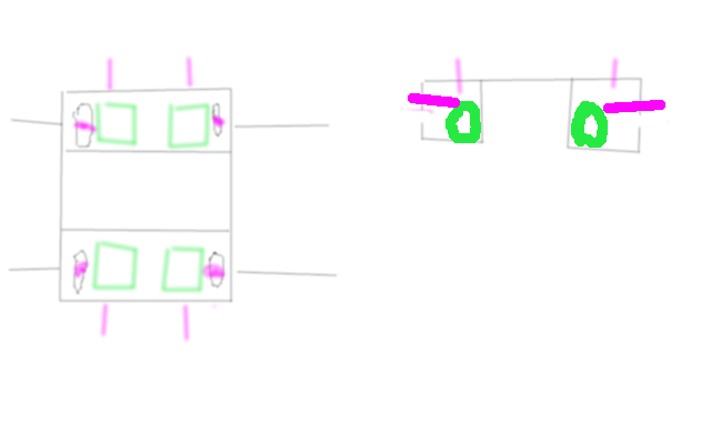
ok rough diagram, bearings in green, bolts in purple
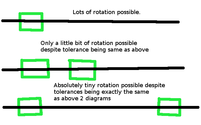
so, bolts come in from size, squash bearings into corner. also, following on from yesterday, making the carriage as long as will fit (a longer distance between the LM8UU bearings on the same rod) will be a way to minimise that rotation about the Y axis, illustrated here:
so the further apart the bearings, the less the rod can rotate about those bearings, despite the machining tolerance being exactly the same.
so, let's go through it.
- 2 bearings per rod, with distance maximised, stops y-axis rotation
- adjustment mechanism (slots in plate) allows taking up of machine-tolerance slack to stop both Z and Y upwards and sideways travel in each bearing.
- adjustment mechanism *also* has the side-effect of stopping both z-axis rotation (not completely) and x-axis rotation because the rods are pushed against the inner side of the sets of bearings, preventing travel and thus the carriage cannot rotate either
- even if there is some rotation, the fact that the hotend is close to the centre point means that any rotation is not amplified
- lateral travel is well, if there is any, you just have to put up with that. or get really good rods and bearings.
bear in mind if you have only 2 (LM8LUU) bearings this *won't work*.
it would actually work with SC8UU bearings, by having slots in the plate - but you would not be able to do a maintenance cycle on the bearings to even out the wear due to deliberately taking up machine-tolerance slack. you might only need to do holes on one rod and slots on the other.
Edited 1 time(s). Last edit at 05/29/2016 04:31AM by lkcl.
|
Re: Started designing an efficient Horizontal XCarriage. Looking for your experience and input May 29, 2016 07:16AM |
Registered: 9 years ago Posts: 1,035 |
Quote
lkcl
- 1) 2 bearings per rod, with distance maximised, stops y-axis rotation
- 2) adjustment mechanism (slots in plate) allows taking up of machine-tolerance slack to stop both Z and Y upwards and sideways travel in each bearing.
- 3) adjustment mechanism *also* has the side-effect of stopping both z-axis rotation (not completely) and x-axis rotation because the rods are pushed against the inner side of the sets of bearings, preventing travel and thus the carriage cannot rotate either
- 4) even if there is some rotation, the fact that the hotend is close to the centre point means that any rotation is not amplified
- 5) lateral travel is well, if there is any, you just have to put up with that. or get really good rods and bearings.
Thanks for the input, it's all nice and dandy, BUT:
1) maximized distance between bearings have to be the minimized distance that will permit enough printing area. This is tricky and I've thought about a Variable-Width-Carriage that will be able to be re-configured (manually or automatically) so that the scheduled print will fit inside the printing area defined by the new width. But I might introduce more slop with this variable distance between bearings so I left the idea aside for a while;
I can go as wide as the following image and as narrow as the second one:
2) slots are difficult to make with limited tools at home so I tend to avoid them. Moreover I have no idea where I can get such a small ALU plate (or what other mass-produced item to hack to get one).
3),4),5) ... all these are true IF i go with the segments of ALU tube. Now about the ALU tube:
A ) Currently my design is conceived around 20x20x2mm tubes and the bearings would have been inserted into left-outs of those tubes after the frame piece were cut to length. If those tubes can't be used then i have two choices, namely to go with 3D-printed XCarriage or to use larger tube alltogether, ex 25x25 or 30x30 (which would help with the overall strength but will make a bit bulkier machine)
B ) Is the trouble of working with the tubes and finding and slotting an ALU plate worth it compared with a 3D-printed XCarriage?
C ) ALU is quite weak, pressing bearing against two walls of some specific tube (25x25 most likely) will quickly damage those walls because the actual contact between the cylinder of the bearing and the straight face of the ALU tube wall is a line, which would get dug into by the bearing with vibrations (over time). The side bolts will help taking out this gained slop by the maintenance you are talking about, so that from time to time the bearings get rotated and the bolts re-tightened.But again, is it worth it compared to a 3D-printed carriage? ...
Edited 5 time(s). Last edit at 05/30/2016 03:49AM by realthor.
RepRap Lander concept on Concept Forge
RepRap Lander concept on RepRap Forums
My Things, mostly experimental stuff
|
Re: Started designing an efficient Horizontal XCarriage. Looking for your experience and input May 29, 2016 08:48AM |
Registered: 9 years ago Posts: 1,035 |
This is how it would look with 25x25x2mm tubes and M4 Bolts+Locknuts:
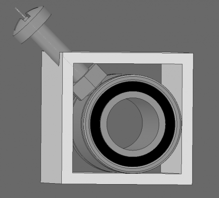
Edit: I wasn't happy with the extra width the carriage would gain by switching to larger alu tube so I have scratched my head for a while and tested one idea in CAD. Funny enough it works. Here it is:
The M3 nut doesn't fit on the sides of the 20x20x2mm ALU Tube so that I do the above solution with this smaller tube but the nut almost fits perfectly in the corner. It rests with the edges of the nut though on the inside of the corner but that is'nt necessarily a bad thing as the nut, when fastened, will dig into the ALU and sit into a fixed place there.
Edited 1 time(s). Last edit at 05/29/2016 12:04PM by realthor.
RepRap Lander concept on Concept Forge
RepRap Lander concept on RepRap Forums
My Things, mostly experimental stuff
|
Re: Started designing an efficient Horizontal XCarriage. Looking for your experience and input May 29, 2016 12:38PM |
Registered: 10 years ago Posts: 1,401 |
|
Re: Started designing an efficient Horizontal XCarriage. Looking for your experience and input May 29, 2016 01:14PM |
Registered: 9 years ago Posts: 1,035 |
Quote
ggherbaz
You don't want to use that method to hold the bearings in place, you are better off making a new part in plastic or getting something that support the whole bearing in place.
I have a feeling that pressing the bearing from the side isn't the industry standard but for this application is it really that bad? I don't expect to put a lot of pressure on the bearing to have it stay in place... after all there are plastic parts that you can snap-in the bearings...
Can you please elaborate a bit?
RepRap Lander concept on Concept Forge
RepRap Lander concept on RepRap Forums
My Things, mostly experimental stuff
|
Re: Started designing an efficient Horizontal XCarriage. Looking for your experience and input May 29, 2016 01:45PM |
Registered: 9 years ago Posts: 1,873 |
What size rods are you thinking of using RT? Looking at my printer, any play in the bearings is completely dwarfed by bending of the 8mm rods. The X axis is the worst, but I'm gradually coming around to the idea that 8mm rods have no place in a printer of more than 100mm travel. I've priced up to replace all the rods with 12mm, but haven't made the commitment to do it yet. I'm undecided between upgrading the current printer with 12mm rods, upgrading with linear guides, or leaving this one as is and starting something completely different. Decisions may not be my strong point 

|
Re: Started designing an efficient Horizontal XCarriage. Looking for your experience and input May 29, 2016 02:12PM |
Registered: 9 years ago Posts: 1,035 |
I have 8mm rods for X and 10mm rods for Y and Z. It's the weight that worries me if I go with larger rods. I have 340mm rods in X and 350mm on Y and for a bowden I have calculated flex and it's on the safe side. With motors on it it's a different story...
If I was to go heavier I would serously consider linear guides or go straight to delrin wheels on extrusion a la Quadrap.
Edited 1 time(s). Last edit at 05/29/2016 02:13PM by realthor.
RepRap Lander concept on Concept Forge
RepRap Lander concept on RepRap Forums
My Things, mostly experimental stuff
If I was to go heavier I would serously consider linear guides or go straight to delrin wheels on extrusion a la Quadrap.
Edited 1 time(s). Last edit at 05/29/2016 02:13PM by realthor.
RepRap Lander concept on Concept Forge
RepRap Lander concept on RepRap Forums
My Things, mostly experimental stuff
|
Re: Started designing an efficient Horizontal XCarriage. Looking for your experience and input May 29, 2016 02:34PM |
Registered: 10 years ago Posts: 1,401 |
A bolt isn't the best way to retain a bearing in a loose environment, too much pressure from the bolt and you will deform the bearing or at least tighten it against the rod creating drag issues, it is also one point retention which means that with little time the bearing will slide back and forth in the housing and you will loose printing quality. If the bolt presses against a printed part that press against the whole surface of the bearing, then most of the issues will be eliminated, but still I personally don't like to put any pressure what so ever to the bearings. I rather spend some money getting the right stuff that use inadequate leftover parts.
|
Re: Started designing an efficient Horizontal XCarriage. Looking for your experience and input May 29, 2016 02:40PM |
Registered: 9 years ago Posts: 1,035 |
Quote
ggherbaz
A bolt isn't the best way to retain a bearing in a loose environment, too much pressure from the bolt and you will deform the bearing or at least tighten it against the rod creating drag issues, it is also one point retention which means that with little time the bearing will slide back and forth in the housing and you will loose printing quality. If the bolt presses against a printed part that press against the whole surface of the bearing, then most of the issues will be eliminated, but still I personally don't like to put any pressure what so ever to the bearings. I rather spend some money getting the right stuff that use inadequate leftover parts.
Of course I get your point. But the bolts can be setup to effectively press inside the grooves on the bearing, which are geometrically very strong and the extra walls in there around the bearing core will almost certainly resist well the pressure from the bolt. I would eliminate the sliding back and forth inside the case (but that shouldn't affect quality even if it happens, the precision of the movement is driven by the belts and the sturdiness of the insertion point on the X carriage relative to how well is the hotend clamped in the same carriage).
RepRap Lander concept on Concept Forge
RepRap Lander concept on RepRap Forums
My Things, mostly experimental stuff
|
Re: Started designing an efficient Horizontal XCarriage. Looking for your experience and input May 30, 2016 02:41PM |
Registered: 9 years ago Posts: 1,035 |
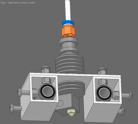
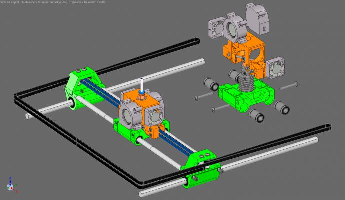
This is where I got with the design. It starts looking usable, still some things to straighten out but overall I am pretty happy with this Horizontal Rods version of an XCarriage but I there are quite a few supplementary hurdles that are introduced when 2 Horizontal Rods are imposed on the design and there are many good things about the Vertical Rods that I want and like. Moreover, in my opinion, this will only work with remote extruders (bowden or flexible shaft) because it's the only way to maintain symmetry that is necessary to balance forces during speedy printing.
Features:
* 60mm XCarriage (the Belt-Catchers go inside the YCarriages so they are not wasted space);
* Belts go in straight line and in the same plane from YCarriages towards the XCarriage;
* Belts can be tensioned with simple screws and dome-nuts pressing on the belt, forcing it into the niche designed for it; belts can be independently tensioned;
* Hotend supported both upside carriage and lower side by the 4 screws;
* Dual-30mm fans for coldend cooling;
* Dual-30mmfan (or squirrelcage blowers) for part cooling [still very undecided here];
* Hotend Mount is quite easily detachable by unscrewing the bolts that clamp the bearings, and another tool can be swapped pretty quickly;
I am thinking about a hybrid between horizontal and vertical... will start designing it soon enough.
Here's the update with photos and explanations:
https://is.gd/JQ5c0k
&Sketchfab model:
https://is.gd/mIcGxK
Edit: If you are not convinced by the text-only explanation above...
Edited 5 time(s). Last edit at 06/01/2016 05:57AM by realthor.
RepRap Lander concept on Concept Forge
RepRap Lander concept on RepRap Forums
My Things, mostly experimental stuff
|
Re: Started designing an efficient Horizontal XCarriage. Looking for your experience and input May 30, 2016 10:02PM |
Registered: 11 years ago Posts: 1,049 |
|
Re: Started designing an efficient Horizontal XCarriage. Looking for your experience and input May 31, 2016 02:44AM |
Registered: 9 years ago Posts: 1,035 |
SC8UU is too bulky for this. The bearing has some wiggle/play in it no matter what casing it has. The plastic casing will be a downside when the forces it's subjected to are greater than the carriage can handle. So for me I will limit the speed because if I want to go high-end there is no stopping for the better and better components you can go with.
I am also thinking that stronger and stronger materials (PET-G for example from what we can currently choose) will emerge and ultimately we will be able to cost-effectively print in aluminum.
I am also not sure SC8UU has any advantage over the LM8LUU, the main concern was that LM8UUs in printed part can't be trusted to lay in perfectly co-linear and that they will bind but that, to some extent, will take away the wiggle/slop in the bearing's tolerance.
Edited 2 time(s). Last edit at 05/31/2016 03:53AM by realthor.
RepRap Lander concept on Concept Forge
RepRap Lander concept on RepRap Forums
My Things, mostly experimental stuff
Sorry, only registered users may post in this forum.
