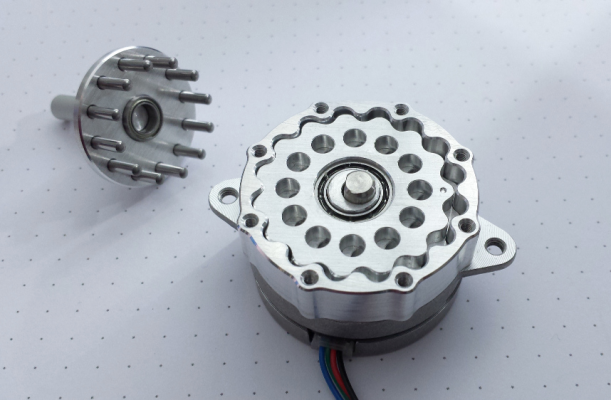
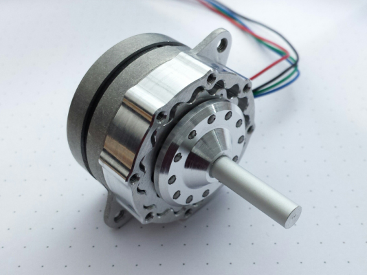
Cycloidal Extruder Drive: A lightweight direct extruder drive unit
Posted by powdermetal
|
Cycloidal Extruder Drive: A lightweight direct extruder drive unit October 04, 2016 04:05PM |
Registered: 8 years ago Posts: 62 |
What it is:
- An extruder including a cycloidal gear reducer
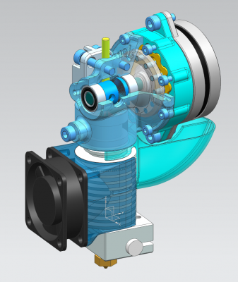
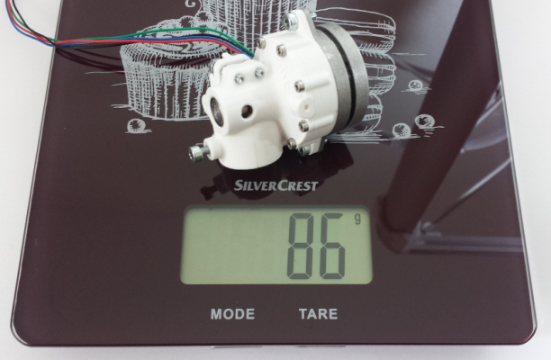
- A lightweight direct drive unit: 86g
- Compact and powerful to drive 3mm and 1.75mm material
- Compatible with E3D's V6 hotend
- Fully experimental (so far)
More details at the Home Page of the Cycloidal Extruder Drive
Some images and movies can be found at the Build v0.4: Google Album
This topic is a spin-off of the extensive RepRap Forum thread "This engineer claims 100 grams direct extruder. I want one" and I'd like to give this thing it's own home for further discussion - thoughts & ideas welcome...
|
Re: Cycloidal Extruder Drive: A lightweight direct extruder drive unit October 04, 2016 04:25PM |
Registered: 10 years ago Posts: 14,672 |
Looks good! Two questions:
1. The BOM says to use the 3mm direct drive variant of the E3D. Can I build a 1.75mm version instead?
2. What is the reason for using a 0.9deg motor? With 16:1 gearing I would have thought 1.8 deg would be adequate.
Large delta printer [miscsolutions.wordpress.com], E3D tool changer, Robotdigg SCARA printer, Crane Quad and Ormerod
Disclosure: I design Duet electronics and work on RepRapFirmware, [duet3d.com].
|
Re: Cycloidal Extruder Drive: A lightweight direct extruder drive unit October 04, 2016 04:49PM |
Registered: 8 years ago Posts: 62 |
Quote
Simon0362
Ping.........!
Anybody advanced any further with this project?
I heavily modified the casing drawings to arrive at something suitable for my Kossel where the E3d hangs underneath the spider but a load of other diversions mean that I don't yet have a fully operational unit - but I am interested to hear how others are getting along.
Having recently moved house, my workshop is slowly getting back to being operational again (the 03D stuff sits in the office!), and this included a CNC mill and lathe which I intend to use to try some of the components in aluminium - especially the outer gear casing and probably the pin carrier and shaft. Update will follow when I get somewhere closer!
Regards,
Simon
Space is very limited at Kossel effectors - so hanging the unit under the spider seems to be the only viable method. I am preparing a single block idler-/adjustment unit - will add some mounting points on the top side to make this task easier.
If you go for machined components, pls include the two eccentric gears as well in Aluminium - their profile's precision and holes' pitch angles are crucial for a uniform transmission. Waiting for my Aluminium parts as well - would whish, I had your equipment...
|
Re: Cycloidal Extruder Drive: A lightweight direct extruder drive unit October 04, 2016 04:56PM |
Registered: 8 years ago Posts: 62 |
Quote
dc42
Looks good! Two questions:
1. The BOM says to use the 3mm direct drive variant of the E3D. Can I build a 1.75mm version instead?
2. What is the reason for using a 0.9deg motor? With 16:1 gearing I would have thought 1.8 deg would be adequate.
1. Yes, you can build in the 1.75mm V6 as well - the CAD files include proper files for the block above the hotend and the idler lever (CycloExtruder_v04_1.75mm-mods.stp). Hope everything works, as I haven't tried it myself so far...
2. 1.8 deg would be fully sufficient - 0.9 deg was just the only model available with 50 grams
|
Re: Cycloidal Extruder Drive: A lightweight direct extruder drive unit October 04, 2016 05:14PM |
Registered: 8 years ago Posts: 16 |
Hi PM - good idea to move and refocus the discussions.
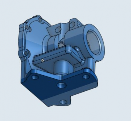
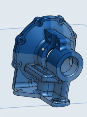
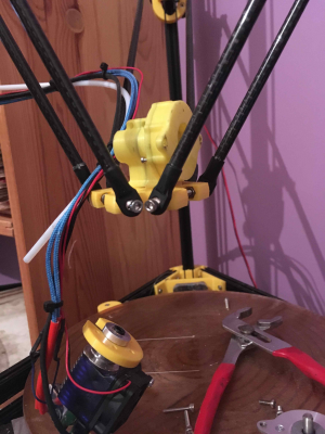
These 3 screenshots show my own adaptation of your mount as described in my 'ping' - BTW, I converted this for 1.7mm instead of 3mm since that is all I use
The intention is that this sits above the spider and the E3D sits underneath with long screws clamping the two parts with the spider in the middle. The setting on my Kossel allow enough room (I hope!) to fit between a pair of arms and not to foul....famous last words of course but the trial runs seem to be ok.
Do you have dxf's of the case and the 2 gears? I can re-draw and convert but I am aware of the potential loss of accuracy each time I move from one CAD to the next...
No hurry, the mill is still idle on the bench awaiting some parts and me to reconnect everything in sight - but this will be a priority run...
Simon
Edited 1 time(s). Last edit at 10/04/2016 05:17PM by Simon0362.
|
Re: Cycloidal Extruder Drive: A lightweight direct extruder drive unit October 04, 2016 08:01PM |
Registered: 9 years ago Posts: 978 |
If you have a threaded 6mm hole for the filament to pass through, then you can use a stainless steel heatbreak, cut down to the right length, as a filament guide. Whether the filament is 3mm or 1.75mm, the only thing to change would be the guide. The stainless steel also makes the extruder longer-lasting, since the filament doesn't grind away the edge as if it were plastic or aluminium. The end of the guide can also be positioned very close to the drive cog, to minimise jams due to the filament bending.
Any thoughts on driving this via cable rather than directly by the stepper motor?
Any thoughts on driving this via cable rather than directly by the stepper motor?
|
Re: Cycloidal Extruder Drive: A lightweight direct extruder drive unit October 17, 2016 06:34AM |
Registered: 13 years ago Posts: 35 |
Quote
frankvdh
Any thoughts on driving this via cable rather than directly by the stepper motor?
HI, as you see this extruder holds the motor shaft perpendicularly against filament path. On the other hand, bowden + remote motor configration holds the flexible drive shaft in parallel against filament path around the extruder. So, it's not suitable for coaxial speed reducer, rather worm + pinion gear combination is better like as Flex3Drive.
Edited 2 time(s). Last edit at 10/17/2016 07:03AM by Genie.
Genie - designer of bitfab::Hexagon Heatedbed in purple. PM me if you wish to get original one of the best quality.
|
Re: Cycloidal Extruder Drive: A lightweight direct extruder drive unit October 17, 2016 07:02AM |
Registered: 13 years ago Posts: 35 |
Hi powdermetal,
Recently, I'd read the previous thread and strongly interested in your design. Then I asked my friends to join for group buying of NEMA 14 pancake stepper to replicate the experiment. Now we share a couple of steppers each among three guys, and another one is going to buy himself. Parts on BOM are already in the hands. Slowly starting, I hope it will go well.
Genie - designer of bitfab::Hexagon Heatedbed in purple. PM me if you wish to get original one of the best quality.
Recently, I'd read the previous thread and strongly interested in your design. Then I asked my friends to join for group buying of NEMA 14 pancake stepper to replicate the experiment. Now we share a couple of steppers each among three guys, and another one is going to buy himself. Parts on BOM are already in the hands. Slowly starting, I hope it will go well.

Genie - designer of bitfab::Hexagon Heatedbed in purple. PM me if you wish to get original one of the best quality.
|
Re: Cycloidal Extruder Drive: A lightweight direct extruder drive unit October 17, 2016 01:13PM |
Registered: 8 years ago Posts: 62 |
Quote
Genie
Hi powdermetal,
Recently, I'd read the previous thread and strongly interested in your design. Then I asked my friends to join for group buying of NEMA 14 pancake stepper to replicate the experiment. Now we share a couple of steppers each among three guys, and another one is going to buy himself. Parts on BOM are already in the hands. Slowly starting, I hope it will go well.
Konnichiwa Genie-San,
thanks for your kind interest. Actually this design was partly inspired by Sumitomo's Cyclo gearboxes - it's good to see some japanese experts joining!
Looking forward to see your builds and hear about your experiences.
|
Re: Cycloidal Extruder Drive: A lightweight direct extruder drive unit October 18, 2016 04:31AM |
Registered: 8 years ago Posts: 16 |
Quote
powdermetal
If you go for machined components, pls include the two eccentric gears as well in Aluminium - their profile's precision and holes' pitch angles are crucial for a uniform transmission. Waiting for my Aluminium parts as well - would whish, I had your equipment...
Hi Powdermetal, all,
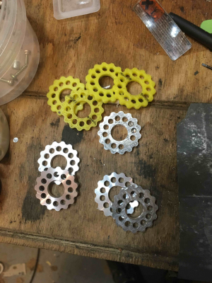
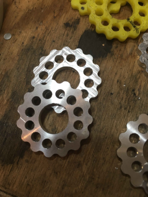
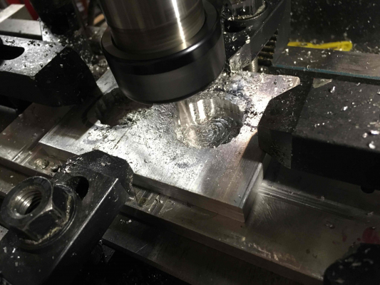
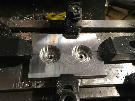
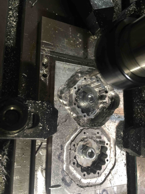
managed to get my CNC mill functioning at the weekend and the first run was the eccentric gears - the photos show two batches (the beauty of CNC to replicate!) along with the trial piece (failed to cut one pin hole!) and a couple of plastic printed pieces in a rather garish yellow...
Could have been easier if I had had some aluminium of the correct thickness instead of having to machine some 6.5mm down.
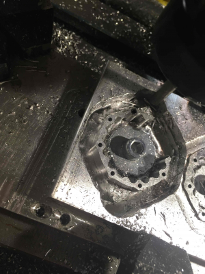
The next couple of pictures show the start of the machining of the gear casing itself - 2 copies again. This is the roughing out of the cycloidal path with a nice chunky 6mm tool, the detailed bit will be done with a petite and delicate 3mm version!
More to follow.......
Simon
|
Re: Cycloidal Extruder Drive: A lightweight direct extruder drive unit October 18, 2016 02:55PM |
Registered: 8 years ago Posts: 62 |
Quote
Simon0362
Hi PM - good idea to move and refocus the discussions.
These 3 screenshots show my own adaptation of your mount as described in my 'ping' - BTW, I converted this for 1.7mm instead of 3mm since that is all I use
The intention is that this sits above the spider and the E3D sits underneath with long screws clamping the two parts with the spider in the middle. The setting on my Kossel allow enough room (I hope!) to fit between a pair of arms and not to foul....famous last words of course but the trial runs seem to be ok.
Do you have dxf's of the case and the 2 gears? I can re-draw and convert but I am aware of the potential loss of accuracy each time I move from one CAD to the next...
No hurry, the mill is still idle on the bench awaiting some parts and me to reconnect everything in sight - but this will be a priority run...
Simon
Simon,
the machining looks promising!
Coming back to the previous post: How does the assembly look like on your spider?
I am still not happy with the packaging: Hanging everything below the spider is fine for the center of mass and the motion direction of action, but reduces build-volume. Also it makes the nozzle more sensitive to any "wiggle" in the printer's actuation system.
Arranging things above the effector may cause interference between the motor and the arms and creates non-balanced forces due to the elevated center of mass. Maybe your design is a good compromise.
Do you still need the DXF's? If so, please let me know.
|
Re: Cycloidal Extruder Drive: A lightweight direct extruder drive unit October 19, 2016 01:12AM |
Registered: 8 years ago Posts: 5,232 |
I was wondering if the outer gear shape has to be milled or could it be build with a plain backplate and dowel pins?
The free ends of the pins would then be pressed in the extruder gear housing.
Such an open design would allow watching the cycloid do it's job, too
Edited 1 time(s). Last edit at 10/19/2016 01:13AM by o_lampe.
The free ends of the pins would then be pressed in the extruder gear housing.
Such an open design would allow watching the cycloid do it's job, too

Edited 1 time(s). Last edit at 10/19/2016 01:13AM by o_lampe.
|
Re: Cycloidal Extruder Drive: A lightweight direct extruder drive unit October 20, 2016 03:26PM |
Registered: 8 years ago Posts: 62 |
Quote
o_lampe
I was wondering if the outer gear shape has to be milled or could it be build with a plain backplate and dowel pins?
The free ends of the pins would then be pressed in the extruder gear housing.
Such an open design would allow watching the cycloid do it's job, too
Yes - can be done: Arranging 16 pins with Dia3.2 at a PCD of 32 will do the job as well. The outer gear's profile is just made of connected radii of virtual pins.
|
Re: Cycloidal Extruder Drive: A lightweight direct extruder drive unit October 20, 2016 05:39PM |
Registered: 8 years ago Posts: 16 |
Quote
Simon,
the machining looks promising!
Coming back to the previous post: How does the assembly look like on your spider?
I am still not happy with the packaging: Hanging everything below the spider is fine for the center of mass and the motion direction of action, but reduces build-volume. Also it makes the nozzle more sensitive to any "wiggle" in the printer's actuation system.
Arranging things above the effector may cause interference between the motor and the arms and creates non-balanced forces due to the elevated center of mass. Maybe your design is a good compromise.
Do you still need the DXF's? If so, please let me know.
Thanks, the machining is proceeding slowly due to 'real' work commitments unfortunately, however I think I will have 2 casings ready soon. I like the idea of the pins but I suspect the net effect will be a higher mass (steel pins >density than Dural/aluminium) and it still requires a 'front plate' to support the extruder end of the pins and omething to attach that front plate to the motor plate. I may play with the design of the casing with this in mind though since it may help the machining process.
Regarding the packaging - I think somewhere along the line I have failed to allow for some of the worst case scenarios so there is some interference - I need much more time to analyse this which I won't have through until sometime next week so my solution may still end up with more changes....I can see me trying to reduce the overall length from the front of the moter to the centreline as much as possible, so maybe yet thinner ball races for instance...
The DXF's - no its actually fine - imported into Onshape, Onshape creates a drawing, export as a DXF, import into CamBam as a dxf and save as CB file, scale to some odd factor (2.5 and 3 so far!) and then create the Gcode....
Edited 1 time(s). Last edit at 10/20/2016 05:40PM by Simon0362.
|
Re: Cycloidal Extruder Drive: A lightweight direct extruder drive unit October 21, 2016 02:54AM |
Registered: 8 years ago Posts: 16 |
Quote
Simon0362
Quote
Regarding the packaging - I think somewhere along the line I have failed to allow for some of the worst case scenarios so there is some interference - I need much more time to analyse this which I won't have through until sometime next week so my solution may still end up with more changes....I can see me trying to reduce the overall length from the front of the moter to the centreline as much as possible, so maybe yet thinner ball races for instance...
.
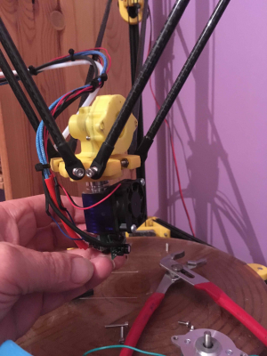
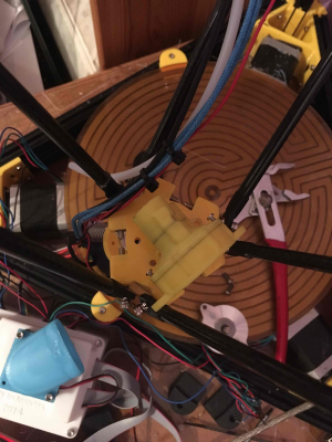
These are how it looks in a rough mockup state to give you an understanding of how I intended it - needs more thought and measurement on my part!
|
Re: Cycloidal Extruder Drive: A lightweight direct extruder drive unit October 21, 2016 08:56AM |
Registered: 8 years ago Posts: 5,232 |
This mockup above is still without stepper. I'm afraid it will interfere with the rods, as soon as they "go sideways"...
My earlier idea I shared with powdermetal was to split stepper and gearbox and put them on each side of the filament drive gear with an extended shaft on the stepper and a hollow shaft as gearbox output. That way the COG would be in the middle of the effector and the chance of interference with the rods would be lower.
Of course one could build an effector where the hotend is mounted off center to give room for the recent in_line version.
Edited 1 time(s). Last edit at 10/21/2016 08:59AM by o_lampe.
|
Re: Cycloidal Extruder Drive: A lightweight direct extruder drive unit October 21, 2016 11:46AM |
Registered: 8 years ago Posts: 16 |
Quote
o_lampe
This mockup above is still without stepper. I'm afraid it will interfere with the rods, as soon as they "go sideways"...
Yup......somehow my original calculations didn't take the extremes into account. 'When' I have some time to spare, I want to draw up the extremes of the available space - I think there are opportunities to reduce the length of the stepper-gearing to help alleviate this problem.
Quote
o_lampe
My earlier idea I shared with powdermetal was to split stepper and gearbox and put them on each side of the filament drive gear with an extended shaft on the stepper and a hollow shaft as gearbox output. That way the COG would be in the middle of the effector and the chance of interference with the rods would be lower.
.
Interesting - I came up with exactly the same idea...but I dont think it works unless you also shorten the stepper o/p shaft because that defines the point at which the central drive shaft can begin.
I also started contemplating a 90° bevel gear to allow the motor to be in the same plane as the effector plate - but more weight, more complexity...
I like the idea of an offset though - rough estimates put the offset at between 5 and 10mm from what I can see...
|
Re: Cycloidal Extruder Drive: A lightweight direct extruder drive unit October 22, 2016 05:31AM |
Registered: 8 years ago Posts: 5,232 |
When using a 90° bevel gear you could completely skip the cycloid gearbox, since there are many readymade bevel gears available from RC-car spares.
Probably adding new issues to feed the filament in a straight way, but worth thinking about.
Maybe a slim/long NEMA11 stepper, sitting parallel to the coldend heatsink, driving the 90° gears would make the smallest footprint and has a low COG.
Stepper and heatsink could both be cooled by one fan, nice!
Edited 2 time(s). Last edit at 10/22/2016 05:50AM by o_lampe.
Maybe a slim/long NEMA11 stepper, sitting parallel to the coldend heatsink, driving the 90° gears would make the smallest footprint and has a low COG.
Stepper and heatsink could both be cooled by one fan, nice!
Edited 2 time(s). Last edit at 10/22/2016 05:50AM by o_lampe.
|
Re: Cycloidal Extruder Drive: A lightweight direct extruder drive unit October 23, 2016 02:57PM |
Registered: 8 years ago Posts: 62 |
Quote
o_lampe
This mockup above is still without stepper. I'm afraid it will interfere with the rods, as soon as they "go sideways"...
My earlier idea I shared with powdermetal was to split stepper and gearbox and put them on each side of the filament drive gear with an extended shaft on the stepper and a hollow shaft as gearbox output. That way the COG would be in the middle of the effector and the chance of interference with the rods would be lower.
Of course one could build an effector where the hotend is mounted off center to give room for the recent in_line version.
Splitting the stepper and gearbox, having the hot end in between is an interesting option - awaiting some long dark winter nights for setting up a digital mockup and check feasibility...
Quote
o_lampe
When using a 90° bevel gear you could completely skip the cycloid gearbox, since there are many readymade bevel gears available from RC-car spares.
Probably adding new issues to feed the filament in a straight way, but worth thinking about.
Maybe a slim/long NEMA11 stepper, sitting parallel to the coldend heatsink, driving the 90° gears would make the smallest footprint and has a low COG.
Stepper and heatsink could both be cooled by one fan, nice!
Using (beveled) gears brings us back to the limited gear ratio of a 1-stage reducer: Spacing constraints and undercutting from small teeth-number make it difficult to exceed a 5:1 ratio, targeting at least 8:1 for 1.75mm material. Applying a stepper with more torque is one way to solve this, taking into account some more weight.
Anyway, there are many different options to go and each one has its strengths...
|
Re: Cycloidal Extruder Drive: A lightweight direct extruder drive unit November 02, 2016 03:06PM |
Registered: 7 years ago Posts: 20 |
Quote
Simon0362
managed to get my CNC mill functioning at the weekend and the first run was the eccentric gears - the photos show two batches (the beauty of CNC to replicate!) along with the trial piece (failed to cut one pin hole!) and a couple of plastic printed pieces in a rather garish yellow...
Could have been easier if I had had some aluminium of the correct thickness instead of having to machine some 6.5mm down.
The next couple of pictures show the start of the machining of the gear casing itself - 2 copies again. This is the roughing out of the cycloidal path with a nice chunky 6mm tool, the detailed bit will be done with a petite and delicate 3mm version!
More to follow.......
Simon
Simon, what thickness of aluminum did you use for the eccentric gears? Also, did you use the same tooling as the housing? Also do you happen to know the weight difference between the aluminum and printed parts?
I have access to a CNC mill and may have to give this a shot since I was having a hard time getting usable prints out of PETG.
Erich
|
Re: Cycloidal Extruder Drive: A lightweight direct extruder drive unit November 03, 2016 04:03AM |
Registered: 8 years ago Posts: 5,232 |
I've milled my gears from POM, a self lubricating plastic. IMHO a perfect combo with the aluminum case.
My gearbox is the V3 6:1 ratio and I stripped filament more than once. There is enough torque for 1.75 filament.
(IMHO the future is even thinner filament, like 1mm dia. Smaller no_bowden_tube extruders are the way to go )
My gearbox is the V3 6:1 ratio and I stripped filament more than once. There is enough torque for 1.75 filament.
(IMHO the future is even thinner filament, like 1mm dia. Smaller no_bowden_tube extruders are the way to go )
|
Re: Cycloidal Extruder Drive: A lightweight direct extruder drive unit November 04, 2016 04:36AM |
Registered: 8 years ago Posts: 16 |
Quote
Simon, what thickness of aluminum did you use for the eccentric gears? Also, did you use the same tooling as the housing? Also do you happen to know the weight difference between the aluminum and printed parts?
I have access to a CNC mill and may have to give this a shot since I was having a hard time getting usable prints out of PETG.
Erich
Hi Erich,
I ended up using some 6.5mm because I didn't have anything thinner - and its actually a beautiful machining aluminium. I machined to full depth plus 0.2 and full 6.5mm on the centre hole and then removed the 2 gears from the mill, hacksawed them out, made a temporary faceplate with a piece of 35mm aluminium rod in my old Unimat 3 lathe, glued the gear to the faceplate with superglue and gently faced the thickness down to the required 3.17mm (1/8"). Not ideal and lots of extra work but it has worked.
If I was to do it in 3mm plate, I would use say 4 tabs to attach but ensuing that they were narrow and not thick so as to prevent any problems cleaning up the tips of the gear teeth.
2 x al gears are 6.9g, 2 x PETG gears are 2.8g.
I have almost finished 2 casings but have a problem with the first - the final cut around the outside was obviously a bit too much so the Y axis lost steps and ploughed neatly across the middle of the perfect and completed inner casing....
 . Awaiting the upgrade bits that are coming on a slow boat from China.
Edited 1 time(s). Last edit at 11/04/2016 07:51AM by Simon0362.
|
Re: Cycloidal Extruder Drive: A lightweight direct extruder drive unit November 04, 2016 03:18PM |
Registered: 8 years ago Posts: 62 |
Quote
Kewtdz
Quote
Simon0362
managed to get my CNC mill functioning at the weekend and the first run was the eccentric gears - the photos show two batches (the beauty of CNC to replicate!) along with the trial piece (failed to cut one pin hole!) and a couple of plastic printed pieces in a rather garish yellow...
Could have been easier if I had had some aluminium of the correct thickness instead of having to machine some 6.5mm down.
The next couple of pictures show the start of the machining of the gear casing itself - 2 copies again. This is the roughing out of the cycloidal path with a nice chunky 6mm tool, the detailed bit will be done with a petite and delicate 3mm version!
More to follow.......
Simon
Simon, what thickness of aluminum did you use for the eccentric gears? Also, did you use the same tooling as the housing? Also do you happen to know the weight difference between the aluminum and printed parts?
I have access to a CNC mill and may have to give this a shot since I was having a hard time getting usable prints out of PETG.
Erich
Erich & Simon,
the thickness of the eccentric gears is not critical: You can use anything from 2.5mm (equals bearing width) up to 3.2mm (results in axial clearances 0.3mm). Maybe you could even go below 2.5mm.
Regarding tooling, a Dia3 milling cutter allows to machine both the splines of the eccentric gears and the housing gear.
When designing these components, manufacturing was planned for
- printability with a FDM-printer and for
- machining by one-sided milling from bar material (all features in one clamp situation for GD&T's) and cutting off the workpieces from the bar by turning
Heinrich
Edited 1 time(s). Last edit at 11/04/2016 03:20PM by powdermetal.
|
Re: Cycloidal Extruder Drive: A lightweight direct extruder drive unit November 05, 2016 02:36PM |
Registered: 7 years ago Posts: 20 |
Thank you all for the information! I'm not sure the extent of the tooling that my local makerspace has but I think much of it is imperial based. Since the parts were designed with a single cutter, I'll probably purchase the required tooling.
Also, o_lampe, I thought of using POM too and wondered if it would work well. After hearing your experience, I'll probably go that direction as I've worked with POM before and it is a wonderful material. I'll make sure to post here as I get things completed.
Also, o_lampe, I thought of using POM too and wondered if it would work well. After hearing your experience, I'll probably go that direction as I've worked with POM before and it is a wonderful material. I'll make sure to post here as I get things completed.

|
Re: Cycloidal Extruder Drive: A lightweight direct extruder drive unit November 05, 2016 03:36PM |
Registered: 8 years ago Posts: 62 |
Quote
Kewtdz
Thank you all for the information! I'm not sure the extent of the tooling that my local makerspace has but I think much of it is imperial based. Since the parts were designed with a single cutter, I'll probably purchase the required tooling.
Also, o_lampe, I thought of using POM too and wondered if it would work well. After hearing your experience, I'll probably go that direction as I've worked with POM before and it is a wonderful material. I'll make sure to post here as I get things completed.
For the final cut you could go with a 0.125 in. cutter, so imperial should work fine (the tightest curvature is 1.65mm in radius).
POM is a very good engineering material and I agree with your positive experiences in manufacturing. From testing there are no issues regarding wear or stability with this gearbox with printed components, so POM sounds like a good step forward.
Edited 1 time(s). Last edit at 11/05/2016 04:09PM by powdermetal.
|
Re: Cycloidal Extruder Drive: A lightweight direct extruder drive unit November 07, 2016 09:34AM |
Registered: 9 years ago Posts: 1,035 |
Please share the results with Acetal, I am too interested in a 3D printed version of this nice development. Great work guys!
RepRap Lander concept on Concept Forge
RepRap Lander concept on RepRap Forums
My Things, mostly experimental stuff
RepRap Lander concept on Concept Forge
RepRap Lander concept on RepRap Forums
My Things, mostly experimental stuff
|
Re: Cycloidal Extruder Drive: A lightweight direct extruder drive unit November 10, 2016 03:08PM |
Registered: 8 years ago Posts: 62 |
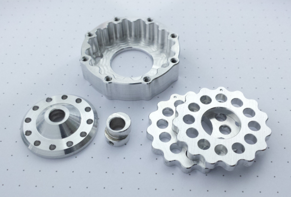
Finally, the precisely-machined components for the all-Aluminium gearbox arrived:
Will see, what the benefit in print quality will be...
Will see, what the benefit in print quality will be...
|
Re: Cycloidal Extruder Drive: A lightweight direct extruder drive unit November 10, 2016 04:29PM |
Registered: 9 years ago Posts: 1,035 |
Wow, that looks fantastic :-o
RepRap Lander concept on Concept Forge
RepRap Lander concept on RepRap Forums
My Things, mostly experimental stuff
RepRap Lander concept on Concept Forge
RepRap Lander concept on RepRap Forums
My Things, mostly experimental stuff
|
Re: Cycloidal Extruder Drive: A lightweight direct extruder drive unit November 11, 2016 06:20AM |
Registered: 8 years ago Posts: 93 |
|
Re: Cycloidal Extruder Drive: A lightweight direct extruder drive unit November 13, 2016 02:57PM |
Registered: 8 years ago Posts: 62 |
Quote
asbo
Looking good powdermetal
Sorry I haven't posted the SolidWorks conversion I said I would, I got frustrated and gave up because I could never get the formula to work properly.
Have you had a look at Omar Younis' well detailed documentation about Building a Cycloidal Drive with SOLIDWORKS?
Sorry, only registered users may post in this forum.
