Discussion on the Nimble
Posted by Lykle
|
Discussion on the Nimble October 23, 2016 04:39AM |
Registered: 8 years ago Posts: 312 |
Hi All,
Overall post to discuss the Nimble
JamesK's question on drive cable length. Of course we can supply different drive cable lengths.
My main test bed is a Delta of 1 meter tall and 32 cm print bed. The cable I use is 91 cm and that it long enough.
For production, the drive cable is spec'd to being 95 cm.
One thing that could help you, is if you can position the stepper half way the 800 mm length. That is the nice thing here, you can position the stepper where it works best.
If this doesn't work for you, just let me know what cable length you do require. If you still have a good length of PTFE tube, you can use that to mock it up and see what length is ok.
Lykle
________________________________________________
Co-creator of the Zesty Nimble, worlds lightest Direct Drive extruder.
[zesty.tech]
|
Re: Discussion on the Nimble October 23, 2016 08:45AM |
Registered: 9 years ago Posts: 1,873 |
|
Re: Discussion on the Nimble October 23, 2016 10:08AM |
Registered: 7 years ago Posts: 137 |
|
Re: Discussion on the Nimble October 23, 2016 11:17AM |
Registered: 8 years ago Posts: 312 |
|
Re: Discussion on the Nimble October 23, 2016 11:23AM |
Registered: 9 years ago Posts: 1,873 |
Oh, don't go to any trouble on my account! I think I over-estimated the requirement anyway, and it's unlikely I'd be actually ordering anything - I like making things too much  I was just experimenting with the flex shaft from my rotary tool, and it looks like around 1m would probably be enough. I do see some unwanted rotation as the shaft is moved around the print area, but I guess the 30:1 gearing keeps that manageable.
The rotary tool drive shafts have a pretty heavy unit at the tool end, I guess you found a better source of flex shaft that is more appropriate.
Best regards,
James
I was just experimenting with the flex shaft from my rotary tool, and it looks like around 1m would probably be enough. I do see some unwanted rotation as the shaft is moved around the print area, but I guess the 30:1 gearing keeps that manageable.The rotary tool drive shafts have a pretty heavy unit at the tool end, I guess you found a better source of flex shaft that is more appropriate.
Best regards,
James
|
Re: Discussion on the Nimble October 23, 2016 01:07PM |
Registered: 8 years ago Posts: 601 |
I'm very interested in the nimble, but I'd like more info on the mounting options. Alot has been said about diamond hot ends etc. I'd like to see the overall weight with hot end + mounting options, even if it was just an e3d. It would also be good to see more pictures of possible prints, but I imagine it is of similar if not better quality then the flex3drive and I've seen good results from that.
It seems there has been some controversy around the zesty nimble, not entirely sure why as there are obvious improvements and a licence agreement made as far as I'm aware.
It seems there has been some controversy around the zesty nimble, not entirely sure why as there are obvious improvements and a licence agreement made as far as I'm aware.
|
Re: Discussion on the Nimble October 23, 2016 02:40PM |
Registered: 8 years ago Posts: 622 |
I've seen the pretty picture of how 3 of them might be grafted onto a Diamond hot end, but knowing how much air is needed to cool the heat sinks, I'd be a bit concerned about the way the Nimbles encroach into the air flow duct. I'd like to seem some data on temperatures at the heat break/transition areas (or some real world testing).
|
Re: Discussion on the Nimble October 24, 2016 02:44AM |
Registered: 8 years ago Posts: 312 |
@Origamib. The overall weight of the unit now is 33 grams, that is including all the screws needed and the Groove mount adapter. On my Delta I have it screwed into an aluminium plate clamping the hot end in the process. The overall weight will drop once we manufacture the actual production units.
@Deckingman. Yes, that is a relevant point. I made an overall assembly to analyse this and will continue to work on it. The pretty picture you have seen was a first blocking.
@Deckingman. Yes, that is a relevant point. I made an overall assembly to analyse this and will continue to work on it. The pretty picture you have seen was a first blocking.
|
Re: Discussion on the Nimble October 24, 2016 04:29AM |
Registered: 8 years ago Posts: 312 |
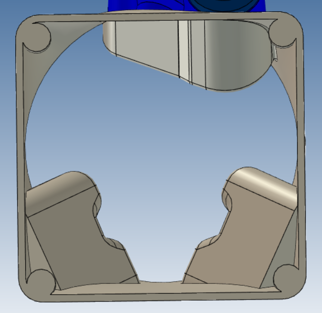
@deckingman. The more detailed look of the shroud for the fan give me the following figures.
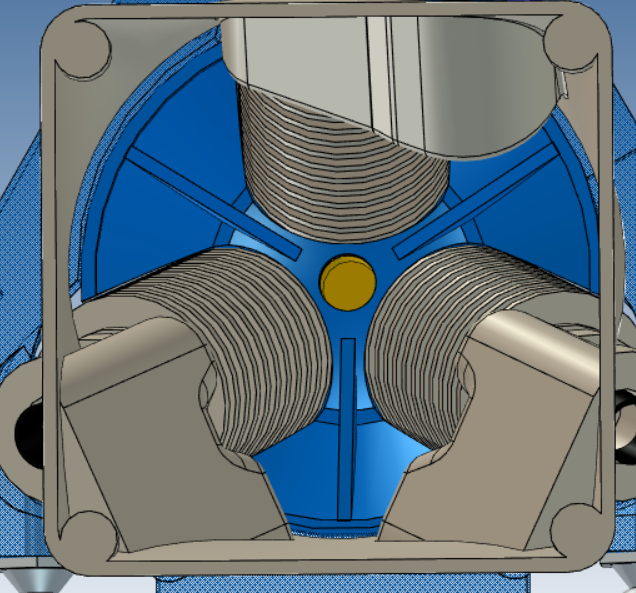
The overall surface area of the fan is 1930 square mm. The overall surface area of the opening at the bottom of the shroud is 1650 square mm. That is actually more that the surface area of the shroud designed by Reprapme. There it is 1590 square mm. The nice thing with the shroud as designed is, that it is clamped by mounting the Nimbles, so they have a double function, making the whole structure a little lighter.
Attached is a quick snapshot of the opening and the shroud in place with the heat sinks.
Lykle
|
Re: Discussion on the Nimble October 24, 2016 12:44PM |
Registered: 8 years ago Posts: 153 |
|
Re: Discussion on the Nimble October 24, 2016 12:55PM |
Registered: 8 years ago Posts: 1,671 |
|
Re: Discussion on the Nimble October 24, 2016 03:01PM |
Registered: 8 years ago Posts: 622 |
Quote
Lykle
@deckingman. The more detailed look of the shroud for the fan give me the following figures.
The overall surface area of the fan is 1930 square mm. The overall surface area of the opening at the bottom of the shroud is 1650 square mm. That is actually more that the surface area of the shroud designed by Reprapme. There it is 1590 square mm. The nice thing with the shroud as designed is, that it is clamped by mounting the Nimbles, so they have a double function, making the whole structure a little lighter.
Attached is a quick snapshot of the opening and the shroud in place with the heat sinks.
Lykle
Er yes but.......on the "stanadard diamond version, the fan is mounted almost directly above the top of the heat sinks and blows air directly down on to them. Unless I'm missing something, it looks like in your version, the nimbles encroach into the airflow and mask the flow over the heat sinks. Maybe it will work - it just doesn't look right. I do know that you need at least 18cfm in the standard design with (fairly) unrestricted flow over the heat sinks. I guess the only thing to do is build one and do some tests. Don't forget you'll need to accommodate some layers of insulation (fire blanket or some such) between the brass nozzle and the heat sinks.
Edited 1 time(s). Last edit at 10/24/2016 03:02PM by deckingman.
|
Re: Discussion on the Nimble October 24, 2016 08:37PM |
Registered: 8 years ago Posts: 1,671 |
|
Re: Discussion on the Nimble October 25, 2016 03:17AM |
Registered: 8 years ago Posts: 312 |
@n8bot, the reason I stated surface area was because there was a concern over the Nimbles encroaching on the flow area.
@deckingman: Yes agreed. I will do a flow analysis of the air in the chamber. It is amazing how sometimes little adjustments make for great improvements. Because the air enters the chamber already swirling, I don't think the Nimbles will block the flow to the heat sinks. Besides, the air has nowhere else to go. I am not worried about achieving flow through the heat sinks. What I am thinking about is the efficiency of that flow. And getting that flow smoothly out the heat sinks. In the end, the only way to know for sure is to test it. And that we will do.
One more thing, these images are for the Delta effector. When mounting it on a Carthesian, there is a lot less encroachment as I do not have to stay clear of the arms.
I did see the insulation and have not forgotten it. The bottom of the heat sink shroud is identical to the standard shroud, in that respect.
@MechaBits: Yes,they could be. That is why we did a lot of analysis and calcs on it.:
|
Re: Discussion on the Nimble October 25, 2016 03:23AM |
Registered: 9 years ago Posts: 425 |
|
Re: Discussion on the Nimble October 25, 2016 03:51AM |
Registered: 8 years ago Posts: 1,671 |
Quote
Lykle
@MechaBits: Yes,they could be. That is why we did a lot of analysis and calcs on it.:
Well if the printed one is working then I'm sure the production one will, but i've never done any injection stuff,
but the reason I ask is, sometimes when you dismantle 'things' that have been injection molded they sometimes have some extra's in there,
bits of thin metal or whatever to give strength where needed, maybe perform some other function too,
was just wondering if something additional in there could improve things?
also surely the injection molded one could be different / smaller ? slightly different as its not 3d printed
or did you use a mega printer to prototype the parts as they would come out the injection process?
Edited 1 time(s). Last edit at 10/25/2016 03:51AM by MechaBits.
|
Re: Discussion on the Nimble October 25, 2016 06:55AM |
Registered: 8 years ago Posts: 312 |
Quote
MechaBits
was just wondering if something additional in there could improve things?
also surely the injection molded one could be different / smaller ? slightly different as its not 3d printed
Correct, we could do inserts, but lucky for us that was not needed. The "forks" as we call them are more than strong enough, especially because we are using fiber reinforced material for the body. Of course we use self lubricating material for the gears, that is standard.
Most of the final prototypes are printed using Shapeways, because that way we could get as close to injection molding as possibe. In the last stages of the testing, getting close to the real shape and real material is critical. The extra cost and time was worth it.
Lykle
|
Re: Discussion on the Nimble October 25, 2016 07:27AM |
Registered: 9 years ago Posts: 425 |
Given you have an extruder product and claim hundreds of hours testing, along with many materials tested, it might be advisable to have a strong selection of good prints to boost your kickstarter potential otherwise people might question the veracity of your product.
I know of only 3 possibly 4 prints you have put in the public domain that were apparently printed with the Zesty. Just in case you have over looked this.
Edited 1 time(s). Last edit at 10/25/2016 08:59AM by Mutley3D.
I know of only 3 possibly 4 prints you have put in the public domain that were apparently printed with the Zesty. Just in case you have over looked this.
Edited 1 time(s). Last edit at 10/25/2016 08:59AM by Mutley3D.
|
Re: Discussion on the Nimble October 25, 2016 12:38PM |
Registered: 8 years ago Posts: 622 |
Quote
MechaBits
wouldnt a fan one the top of the diamond be blowing warm air onto heater block & print? or is it set to suck? or additional ducting?
Take a look here at the original [reprap.org] and you'll see why it doesn't blow on to the heater block. All these guys are doing is adding an extension between the top of the shroud that you'll see and the fan. The nimbles will encroach into this extension part but the lower part will be more or less the same (at least that's how I see it). Also, there are 3 layers of "fire blanket" between the heater block/nozzle and the heat sinks that will help to keep air from the fan reaching the hot part.
Edited 1 time(s). Last edit at 10/25/2016 12:39PM by deckingman.
|
Re: Discussion on the Nimble October 26, 2016 05:01AM |
Registered: 8 years ago Posts: 312 |
Yes, the extra shroud is mainly to create space for the fan
But In your case Deckingman, after looking at your files, I think the Nimbles will fit on your carriage without adding another shroud.
So it will be simpler for you. And a lot lower that the projected solution.
Unless you want to reduce the size of the X carriage, then we need to look again.
Lykle
________________________________________________
Co-creator of the Zesty Nimble, worlds lightest Direct Drive extruder.
[zesty.tech]
|
Re: Discussion on the Nimble October 26, 2016 10:12AM |
Registered: 8 years ago Posts: 622 |
Lykle,
You might be right. Do you have an stl (or ideally OpenScad file) or some such that I could add to my printer design and play around with? I don't need any detail or the internals, just the external shape. I think I'd need to adjust the top part of the x carriage and maybe the way the diamond fixes to it (but I'd planned to do that anyway). I need to make sure it'll clear the 2 horizontal X rails which are pretty close to the top of the heat sinks. I'm also leaning towards doing away with the dual rails and maybe just have a single, deeper rail so I could design a new mount around that idea.
You might be right. Do you have an stl (or ideally OpenScad file) or some such that I could add to my printer design and play around with? I don't need any detail or the internals, just the external shape. I think I'd need to adjust the top part of the x carriage and maybe the way the diamond fixes to it (but I'd planned to do that anyway). I need to make sure it'll clear the 2 horizontal X rails which are pretty close to the top of the heat sinks. I'm also leaning towards doing away with the dual rails and maybe just have a single, deeper rail so I could design a new mount around that idea.
|
Re: Discussion on the Nimble October 26, 2016 02:35PM |
Registered: 8 years ago Posts: 312 |
I just placed an STL file of the Nimble on our Thingiverse page.
[www.thingiverse.com]
But that one is a bit too "blocky" for you, because of the angles, so tomorrow I will send you personally a slightly better model that you can use. Only for you. :-)
Other news,
Since we reached 100 backers today we felt the need to celebrate. We announced the first add-on to the Nimble. It is a filament sensor that clips onto the extruder. It is not finished yet, but we are working on it, together with David Crocker. It will not be part of the campaign.
I need some sleep, goodnight everybody.
Lykle
________________________________________________
Co-creator of the Zesty Nimble, worlds lightest Direct Drive extruder.
[zesty.tech]
|
Re: Discussion on the Nimble October 30, 2016 11:44AM |
Registered: 8 years ago Posts: 312 |
Hi All,
Just to let you know, there is a new Nimble today.
It lost weight, 15% of it, and has a completely new breech loading mechanism. It also reduced in size. (I wish I could go on that diet)
The new Nimble is the main reason we didn't have many photos or videos available, as we were working on this beauty.
Now that we know we have it right, you will see a lot more photos and video appearing.
Lykle
________________________________________________
Co-creator of the Zesty Nimble, worlds lightest Direct Drive extruder.
[zesty.tech]
|
Re: Discussion on the Nimble November 01, 2016 04:48AM |
Registered: 8 years ago Posts: 312 |
Hey all,
Just a quick announcement.
We will release an Open Source Nimble after we have a successful campaign. We made it a stretch goal.
[www.kickstarter.com]
Lykle
Just a quick announcement.
We will release an Open Source Nimble after we have a successful campaign. We made it a stretch goal.
[www.kickstarter.com]
Lykle
|
Re: Discussion on the Nimble November 01, 2016 09:04AM |
Registered: 8 years ago Posts: 1,671 |
I thought it looked like a shapeways print all matte like a powder paint.
Lets hope you guy's are not fleet of foot when project ends, or you dont fly like a bird...in the sky..
(some ppl will be too young to know what the hell i'm going on about)
So what happens to Mutley's royalty on the Open source items?
Edited 3 time(s). Last edit at 11/01/2016 05:42PM by MechaBits.
Lets hope you guy's are not fleet of foot when project ends, or you dont fly like a bird...in the sky..
(some ppl will be too young to know what the hell i'm going on about)

So what happens to Mutley's royalty on the Open source items?
Edited 3 time(s). Last edit at 11/01/2016 05:42PM by MechaBits.
|
Re: Discussion on the Nimble November 01, 2016 11:18AM |
Registered: 8 years ago Posts: 312 |
@MechaBits
Correct, the prototypes are Shapeways parts. The production parts will not be.
We will add all the available adapters to our Shapeways page as well. People can choose how to get the adapter, download and print it or have Shapeways do it.
Most of the adapters will be added to our website as well as STEP files, to allow people to edit and change them where needed. I say most, because a lot of the adapters are being designed by people who are getting the Nimble and it might be that somebody doesn't want to share. Hope not, but I have learned to be careful.
There are no royalties, there is a license agreement.
Lykle
|
Re: Discussion on the Nimble November 01, 2016 11:32AM |
Registered: 8 years ago Posts: 1,671 |
|
Re: Discussion on the Nimble November 01, 2016 02:32PM |
Registered: 9 years ago Posts: 1,873 |
|
Re: Discussion on the Nimble November 02, 2016 04:00AM |
Registered: 8 years ago Posts: 601 |
|
Re: Discussion on the Nimble November 02, 2016 06:47AM |
Registered: 9 years ago Posts: 1,873 |
That worried me too, however, the tension is determined by the position of the idler axle and I think it would be fairly easy to print a few clamps with different axle offsets for different filaments.Quote
Origamib
I've noticed that you can't change the tension on the filament, this is one thing determined by your design and the breach system.

Sorry, only registered users may post in this forum.